Note : Les descriptions sont présentées dans la langue officielle dans laquelle elles ont été soumises.
CA 02638352 2008-07-25
ROTARY RETENTION LATCH FOR REPLACEABLE SKATE BLADE
SYSTEMS
BACKGROUND
Ice skates have been used for recreational and transportation purposes for
hundreds of
years. Originally, some sort of low friction sliding device akin to a metal
blade was
attached using straps to a conventional boot. Ultimately, in the past century,
boots
specifically intended for use only in ice skating evolved, typically with the
blade firmly
affixed to the boot. The unitary blade and boot had the advantage of rigidity
allowing
more speed and control than previously possible.
For many years, it has been understood that there may be an advantage to
providing a
replaceable sharpened blade for ice skates. With heavy use, typically a
conventional
skate blade will wear out before the boot portion. Accordingly, there is an
advantage to
extending the life of the skate by replacing the blade rather than replacing
the entire
skate.
Certain of the prior art attempts to provide replaceable skate blades have
involved
replacement of a relatively heavy, and thus expensive, metal portion of the
skate with
substantial removal and fastening difficulties. Some such replaceable blades
were
intended to be sharpened a number of times before replacement. See, for
example U.S.
Pat. No. 5,088,749 to Olivieri. In other prior art attempts, the replaceable
blade, although
lightweight, has not been effectively mounted on the rocker to provide the
security
required particularly by advanced skaters. See, for example, U.S. Pat. No.
2,108,128 to
Kinney. Still other replacement blades have been of a complex construction not
easily
adapted to inexpensive commercial production. See, for example, German Patent
No.
724488 to Dornseif and U.S. Pat. No. 3,947,050 to Isely. Moreover, replaceable
blades
have tended to be prone to breakage owing to the structure of the blade and
the tension
under which the blade is placed in order to stretch it along the base of a
skate blade. See,
for example, U.S. Pat. No. 5,383,674 to Cann, et al.
U.S. Pat. No. 5,988,683 to Venier et al. describes a replaceable blade system
in which the
shortcomings of the prior art, including the excess breakage associated with
the Cann
patent configuration, has been solved using a novel means to connect the
flexible
replaceable blade to the skate so that it is pulled more or less
longitudinally and tensioned
evenly along its length. A torque limiting device provides for easy
replacement and
adjustment of blades by consumers without damage to the skate or the
replaceable blade.
A limitation of this arrangement is that the associated attachment and
tensioning
mechanism is complex and requires a separate torque limiting tool to operate.
An
additional problem of the Venier patent is that the tensioning mechanism
requires a high
stiffness and high strength rigid holder for mounting.
CA 02638352 2008-07-25
-2-
U.S. Pat. No. 5,123,664 to DeMars describes a blade system that includes a
replacement
runner that may be rapidly, removably coupled to the holder of the skate. The
blade
system of DeMars utilizes a single piece, replacement runner that integrally
incorporates
a blade and is adapted to be retained in the holder of the skate by a slot and
pin at its
forward end and a locking mechanism at its rear end. The locking mechanism
consists
of a linear sliding latch with an array of springs and a release button
located in the rear
face of the holder. A limitation of this arrangement is that it requires a
highly complex
shaped cavity within the skate holder to interact with the linear sliding
latch member. A
further limitation of the DeMars patent is that the release button can only be
placed on the
rear face of the holder where inadvertent release could be induced by contact
with hockey
sticks, pucks and the like. Another problem with this configuration is that it
requires an
ejection mechanism to aid in removing the runner from the holder. Finally, the
linear
sliding latch mechanism of DeMars could not be integrated into styled holders
that
incorporate aesthetic apertures.
The present invention solves these prior art problems by providing a simple
rotary
retention latch located within an enclosed chamber of the holder of the skate.
The rotary
retention latch is configured with a release lever that is adapted to be
accessed through an
aesthetic aperture in the holder. This rotary latch configuration can be
utilized to retain a
pivoting rocker section that holds a flexible replaceable blade in tension or
for securing a
single piece, replaceable runner that integrally incorporates a blade. This
arrangement is
superior to the Venier configuration in that it does not require a separate
torque limiting
tool to operate, the tensioning loads are contained within the rocker so the
holder can be
constructed from regular plastic materials and the number of parts and
complexity are
significantly reduced. Additionally this arrangement is superior to the DeMars
prior art
in that it eliminates the requirement for a highly complex shaped cavity in
the holder and
integrates the release lever into an aesthetic aperture in the holder
preventing inadvertent
release induced by contact with hockey sticks, pucks and the like. This
configuration of
rotary latch that includes an integrated release lever accessed through an
aesthetic
aperture is extremely well suited to the industry standard hollow molded
holders and
provides a solution for holders that are styled with aesthetic apertures.
SUMMARY OF THE INVENTION
Accordingly, the ice skate of the present invention comprises a boot and a
holder that is
adapted to be mounted to the boot. The holder is of a generally hollow
construction
containing at least one substantially enclosed chamber. The holder is
additionally styled
with at least one aesthetic aperture. The aesthetic apertures are incorporated
in the holder
to give it a distinct appearance and are utilized to differentiate the ice
skate from
competitive products. Additionally, the configuration of the apertures
contributes to
providing a predetermined holder stiffness that enhances the skating bio-
mechanics. The
ice skate additionally includes a downward facing blade system and a unique
rotary
retention latch. The blade system includes a lower surface of a first defined
curvature
and is configured with at least one blade engagement system and comprises a
blade along
its lower surface. The rotary retention latch is pivotally mounted to the
holder and is
CA 02638352 2008-07-25
-3-
substantially located in the enclosed chamber of the holder and is configured
to move
between a blade securing position and a blade releasing position. The rotary
retention
latch is further configured with an attachment engagement portion accessible
through a
first opening to the enclosed chamber and a release lever accessible through
the aesthetic
aperture and adapted to move the rotary retention latch between the blade
securing
position and the blade releasing position. The rotary retention latch is
adapted to be
biased to the blade securing position by at least one biasing device. The
blade system is
retained in the holder via the blade engagement system detachably mating with
the
attachment engagement portion when extended through the first opening in the
holder
and when the rotary retention latch is in the blade securing position
In an aspect of the invention, the blade is integral with the blade system.
In a further aspect of the invention, the blade system is configured with a
second blade
engagement system configured as a retention hook that detachably engages to a
retention
pin that is rigidly attached to the holder.
In a further aspect of the invention, the attachment engagement portion of the
rotary
retention latch is a pawl feature and the blade engagement system of the blade
system
comprises a striker feature.
In a further aspect of the invention, the biasing device is a spring.
In an alternative embodiment of the invention, the blade system comprises a
downward
facing rocker with a lower surface of the first defined curvature and a front
end and a rear
end. The blade system also includes a flexible replaceable blade having a
second
curvature when not attached to the rocker. The flexible replaceable blade
incorporates an
upper surface, a lower ice-contacting surface, a front end and a rear end and
is adapted to
be removably mounted to the rocker. The front end of the rocker is configured
with a
front securing means for attaching the front end of the flexible replaceable
blade. The
rear end of the rocker is configured with a rear securing means for attaching
the rear end
of the flexible replaceable blade. The flexible replaceable blade conforms to
the first
defined curvature of the rocker when mounted thereon. In this way a skater can
easily
release a used flexible replaceable blade from the rocker and simply change it
for a new
replaceable blade. The flexible replaceable blade curvature will then conform
to the first
defined curvature of the downward facing rocker.
In a further aspect of the alternative embodiment of the invention, an ice
skate comprises
a boot and a holder that is adapted to be mounted to the boot. The holder is
of a generally
hollow construction containing at least one substantially enclosed chamber.
The holder is
additionally styled with at least one aesthetic aperture. The aesthetic
apertures are
incorporated in the holder to give it a distinct appearance and are utilized
to differentiate
the ice skate from competitive products. Additionally, the configuration of
the apertures
contributes to providing a predetermined holder stiffness that enhances the
skating bio-
mechanics. The holder additionally incorporates an integral, downward facing
rocker
with a lower surface of a first defined curvature. The downward facing rocker
includes a
CA 02638352 2008-07-25
-4-
fixed front end and rear end adapted to rotate between an open position and a
closed
position. The ice skate also includes a flexible replaceable blade having a
second
curvature when not attached to the skate. The flexible replaceable blade has
an upper
surface, a lower ice-contacting surface, a front end and a rear end and is
adapted to be
removably mounted to the rocker. The front end of the rocker is configured
with a front
securing means for attaching the front end of the flexible replaceable blade.
The rear end
of the rocker is configured with a rear securing means for attaching the rear
end of the
flexible replaceable blade. The ice skate also includes a rotary retention
latch pivotally
mounted to the holder and substantially located in the enclosed chamber of the
holder for
movement between a blade securing position and a blade releasing position. The
rotary
retention latch incorporates a pawl feature accessible through a first opening
to the
chamber and a release lever accessible through the aesthetic aperture
configured to move
the rotary retention latch between the blade securing position and the blade
releasing
position. Rotation of the rear end of the rocker between an open position and
a closed
position creates a tension along the length of the flexible replaceable blade
without
exerting the major component of tensioning force around a small radius in the
region of
the front and rear securing means and wherein the flexible replaceable blade
conforms to
the curvature of the lower surface of the rocker when mounted thereon, and the
rotary
retention latch retains the rotatable rear end of the rocker in the closed
position when in
the blade securing position.
Further aspects of the invention will become apparent from the following
description.
BRIEF DESCRIPTION OF THE DRAWINGS
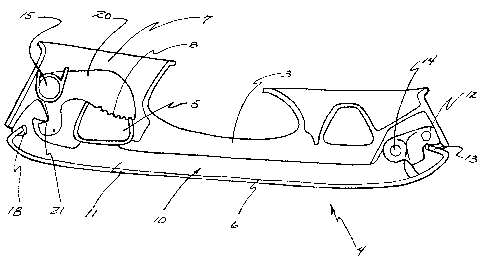
FIG. 1 is a side view of the replaceable blade ice skate assembly;
FIG. 2 is a schematic view of the holder, rocker, flexible replaceable blade
and rotary
retention latch shown in the closed position;
FIG. 3 is a schematic view of the holder, rocker, flexible replaceable blade
and rotary
retention latch shown in the open position;
FIG. 4 is a schematic view of the holder, blade system and rotary retention
latch shown in
the secured position;
FIG. 5 is a schematic view of the holder, blade system and rotary retention
latch shown in
the released position;
FIG. 6 is a perspective view of the retention latch;
DETAILED DESCRIPTION OF THE INVENTION
Referring to Figure 1, a replaceable blade ice skate assembly (1) is
substantially
constructed from a boot (2), a holder (3) adapted to be mounted to the boot
and a
downward facing blade system (4). The holder (3) is styled to include at least
one
aesthetic aperture (5). It will be appreciated that this aperture could also
have non-
aesthetic functions, such as affecting the flexibility of the holder.
Figures 2 and 3 illustrate a flexible replaceable blade system that consists
of a downward
facing blade system (4) that includes a rocker (10) that is configured with a
first defined
CA 02638352 2008-07-25
-5-
curvature along its lower ice-contacting surface and incorporates a front end
(12) and a
rear end (11) and a flexible replaceable blade (6). The rocker front end (12)
is adapted to
be immovably attached to the holder (3) via riveting, bolting or similar
fastening means
and is configured with a toe receiving area (13). The rocker front end (12) is
configured
with a pivot joint (14) which is adapted to align with an appropriate
clearance hole
configured in the holder (3). The rocker rear end (11) is adapted to be
rotatably attached
to the rocker front end (12) at the pivot joint (14) via a bushing and rivet
or similar
means. The rocker rear end (11) is configured with a blade system engagement
portion
(16) and a heel receiving area (18). A rotary retention latch (20) is adapted
to be
pivotally mounted to the holder (3) at a latch pivot point (15) and contained
within a
substantially enclosed chamber (7) within the holder. The rotary retention
latch (20) is
configured with a release lever (8) and an attachment engagement portion (21).
The
attachment engagement portion (21) is configured to interlock with the blade
system
engagement portion (16) which accesses the attachment engagement portion (21)
through
a first opening in the holder to the chamber (7) so as to rigidly restrain the
rocker portion
rear end (11) in a closed position. The release lever (8) of the rotary
retention latch (20)
is adapted to be accessible through the aesthetic aperture (5) of the holder
(3).
Referring to Figure 3, a flexible replaceable blade (6) is configured with a
second defined
curvature and incorporates a front hook (49) and a rear hook (51). The front
hook (49) is
adapted to interlock with the toe receiving area (13) of the rocker front end
(12) and the
rear hook (51) is adapted to interlock with the heel receiving area (18) of
the rocker rear
end (11).
In a preferred embodiment of the invention, the blade engagement system (16)
comprises
a striker feature. The rotary retention latch (20) is adapted to be pivotally
mounted to the
holder (3) at a latch pivot point (15) and the attachment engagement portion
(21)
comprises a pawl feature. The pawl feature (21) is configured to interlock
with the
striker feature of the blade system engagement portion (16) so as to rigidly
restrain the
rocker rear end (11) in a closed position.
Figure 6 illustrates the rotary retention latch (20) that would be typically
manufactured
from moulded plastic such as Nylon. The rotary retention latch (20) is
configured with a
pawl feature (21), release lever (8) and a pivot hole (22). A biasing device,
preferably a
spring (23) that would be typically manufactured from steel wire, is
configured so as to
impart a torque that biases the pawl feature (21) into contact with the
striker feature of the
blade system engagement portion (16) of the rocker rear end (11) as
illustrated in Figure
2. When a skater imparts an operating force on the release lever (8) the
spring torque is
overcome and the pawl feature (21) is released from the striker feature of the
blade
system engagement portion (16) allowing the rocker rear end (11) to rotate
from the
closed to the released position as illustrated in Figure 3. The shape and
geometric
association of the release lever (8) relative to the pivot hole (22) is
configured so as to
place it within the aesthetic aperture (5) of the holder (3) and make it
appear to be
integrated into the overall style of the boot (2) and holder (3).
CA 02638352 2008-07-25
-6-
The process of attachment of the blade to the rocker will now be described in
further
detail. The rocker rear end (11) is placed in its released position as
illustrated in Figure 3.
The front hook (49) of the flexible replaceable blade (6) is hooked into the
toe receiving
area (13). Next, the rear hook (51) of the flexible replaceable blade (6) is
hooked into the
heel receiving area (18). The rocker rear end (11) is then rotated around the
pivot joint
(14) towards the closed position. As the rocker rear end (11) rotates, the
heel receiving
area (18) moves rearward relative to the toe receiving area (13) due to the
radius defined
by the pivot joint (14) being shorter than that defined by the overall
flexible replaceable
blade (6) length. The rearward movement of the heel receiving area (18) causes
the
flexible replaceable blade (6) to be tensioned substantially along its
longitudinal axis.
This helps to prevent the blade from breaking owing to excessive bending
stress which
can occur if the blade is tensioned around a corner or small radius (as would
occur in
certain prior devices such as Cann). As the flexible replaceable blade (6) is
tensioned and
pulled onto the downwardly facing rocker (10), its curvature conforms to the
first defined
curvature of the downwardly facing rocker (10). When the rocker rear end (11)
reaches
the closed position, the pawl feature (21) of the rotary retention latch (20)
is biased into
engagement with the striker feature of the blade system engagement portion
(16) by the
latch spring (23) so that the rocker portion rear end (11) is rigidly
restrained in position.
In this manner the limitations of the Venier patent are overcome by
eliminating the need
for a separate torque limiting tool to tension the flexible replaceable blade
and the
requirement for a high stiffness and high strength rigid holder is avoided.
An additional preferred embodiment of the present invention is illustrated in
Figures 4
and 5. This embodiment involves the usage of a single piece, downward facing
blade
system which integrally incorporates a blade and is attached to the holder (3)
via the
previously described flexible replaceable blade retention system. This
configuration is
substantially constructed from a boot, a holder (3) adapted to be mounted to
the boot and
a blade system (50). The holder (3) is configured with a latch pivot point
(15), and a
retention pin (30) in the same location as the previously described pivot
joint (14). The
blade system (50) may be comprised of heat treatable steel which can be
through
hardened to Rockwell "C" scale 48 or greater. Hardenable varieties of
stainless steel may
be used to provide corrosion resistance. The blade system (50) is configured
with a lower
surface of a first defined curvature and incorporates a blade (52) along the
lower surface,
a front retention hook (54) and a striker feature (56). A rotary retention
latch (20)
identical to the previously described embodiment is adapted to be pivotally
mounted to
the holder (3) at a latch pivot point (15) and contained within a
substantially enclosed
chamber (7) within the holder. The rotary retention latch (20) is configured
with a
release lever (8), a pawl feature (21) and a pivot hole (22). The blade system
(50) is
adapted to be retained in the holder via the front retention hook (54)
interlocking with the
retention pin (30) and the rotary retention latch pawl feature (21)
interlocking with the
striker (56) as in the previously described embodiment. The release lever (8)
of the
rotary retention latch (20) is adapted to be accessible through the aesthetic
aperture (5) of
the holder (3). In this manner the deficiencies of the DeMars prior art are
overcome by
eliminating the requirement for a highly complex shaped cavity in the holder
and
integrating the release lever (8) into the aesthetic aperture (5) prevents
inadvertent release
induced by contact with hockey sticks, pucks and the like.
CA 02638352 2008-07-25
-7-
The foregoing description is intended to be illustrative of preferred
embodiments of the
invention. Variations of the construction described will be obvious to those
skilled in the
art and are intended to be covered by this invention.