Note : Les descriptions sont présentées dans la langue officielle dans laquelle elles ont été soumises.
CA 02638420 2008-07-30
Horizontally graded structures for electrochemical and electronic devices
Field of the invention
The present invention relates to a horizontally graded multilayer structure
suitable for
use as an electrode in electrochemical devices and to a method for producing
same.
Other applications of the graded multilayer structure include protective
coatings for
corrosion or mechanical wear.
Background of the invention
In a normal Ni-yttria stabilized zirconia (YSZ) anode of a solid oxide fuel
cell (SOFC),
which is operated on externally reformed methane, there is a temperature
distribution
over the cell in the order of about 150 C at an operational temperature of 850
C. Such
a gradient has a detrimental effect on the mechanical as well as the chemical
durabil-
ity of the cell, and can for instance cause mechanical failure or enhanced
chemical
reactions in the warmest regions, as discussed, for example, in N. Q. Minh,
and T.
Takahashi, Science and Technology of Ceramic Fuel Cells, (Elsevier Science B.
V.,
Amsterdam NL, 1995), and High Temperature Solid Oxide Fuel Cells:
Fundamentals,
Design and Applications, Eds. S.C. Singhal and K. Kendall. This will in return
inevita-
bly result in a performance decrease of the cell over time. It is therefore
desired to
level the temperature gradient, as this will result in an overall increase in
cell perform-
ance because the temperature of the colder parts of the cell is increased.
In the case of an internal reformation of wet natural gas, such as methane, in
the cell,
the temperature gradient will be even steeper than described above due to the
endo-
thermic reforming process at the inlet, and will thus be more damaging to the
cell (and
stack), as disclosed, for example, in Hendriksen, P. V., Model studies of
internal
steam reforming in SOFC stacks, Proceedings - Electrochemical Society (1997),
97-
40 (Solid Oxide Fuel Cells V).
However, if dry natural gas is employed instead, the formation of carbon will
result in
a fast blocking of the active sites in the anode structure. This may be
prevented by
using, e.g. an all-ceramic anode for direct conversion of natural gas to CO,
CO2 and
1
CA 02638420 2008-07-30
water at the inlet which further down the stream may be replaced by Ni-
containing
electrode for a more efficient conversion. Carbon formation may also be
prevented by
a slower conversion at the inlet.
It has been suggested to use electrodes for SOFC or other electrochemical
devices
which are graded vertically to optimise the ionic and electronic conductivity
of the
electrodes. US patent 5,543,239 discloses an improved electrode design for
solid
state devices, wherein a porous layer of electrolyte material is incorporated
over the
dense electrolyte, and wherein an electrocatalyst which is also continuous is
incorpo-
rated into the porous layer.
EP-A-1701402 relates to systems and methods for minimizing temperature differ-
ences and gradients in solid oxide fuel cells. A manifold heat exchanger is
used,
which reduces thermal stress and increases cell life. Air passes from a
periphery of a
cell towards the cell centre, absorbs the heat, and proceeds to the manifold
heat ex-
changer adjacent to the cell, where it absorbs further heat. Fuel is directed
counter
current to the air, which keeps hot spots away from the cell stack seals and
directs
hot air towards intense reforming areas on the cell to mitigate quenching
effects of
internal reforming.
US patent 6,228,521 concerns a high power density solid oxide fuel cell having
a
cathode, electrolyte and graded porous anode. The anode is formed from NiO and
zirconium oxide doped with yttrium oxide and exhibits a graded density which
allows
thicker and thus stronger anodes without sacrificing electrochemical
performance.
US patent 4,329,403 relates to an electrolyte-electrode assembly for high
temperature
fuel cells in which the electrolyte member is adapted to exhibit a more
gradual transi-
tion in coefficient of thermal expansion in going from the anode electrode to
the inner
electrolyte region and in going from the cathode electrode to the inner
electrolyte re-
gion.
US patent 5,171,645 discloses a graded metal oxide electrolyte comprising
gradia-
tions of zirconia and bismuth oxide across the cross-section of the
electrolyte. The
gradiation of the compositional content across the wall thickness of the
electrolyte
2
CA 02638420 2008-07-30
from a substantially pure zirconia surface zone to a substantially pure
bismuth oxide-
yttria surface zone minimizes the stress at the interfaces between the various
compo-
sitional zones.
US-A1-2005/0092597 relates to a method of forming a thin-film fuel cell
electrode,
comprising the provision of a substrate and at least one deposition device;
developing
a deposition characteristic profile having at least one porous layer based on
pre-
determined desired electrode properties; and forming a film in accordance with
said
deposition material from said deposition device while varying a relative
position of
said substrate in relation to said deposition device with respect to at least
a first axis.
As the deposition device, sputter guns are used. However, said sputter guns
result in
varying thickness as the overlapping areas are thicker than the surrounding
areas,
which leads to unwanted variations of the layer properties in a horizontal
direction.
J.A. Labrincha et al., "Evaluation of deposition techniques of cathode
materials for
solid oxide fuel cells", Mat. Res. Bull., Vol. 28, pp. 101-109, 1993,
discusses specific
cobaltates and manganates as cathode materials for solid oxide fuel cells,
wherein
the cathode layer was applied on an electrolyte layer by sputter deposition.
EP-A-1441406 discloses a method for making a fuel cell anode, comprising the
steps
of:
- depositing a first film on a first end region of a substrate, wherein the
first film is
preferentially catalytically active towards substantially unreformed
hydrocarbon fuel;
and
- depositing a second film on a second end region of the substrate, the second
end
region opposed to the first end region, wherein the second film is
preferentially cata-
lytically active towards at least one of substantially reformed or partially
reformed hy-
drocarbon fuel, by-products thereof and mixtures thereof.
US-A-2004/0086633 discloses a method for the fabrication and evaluation of
elec-
trode and electrolyte materials for use in solid oxide fuel cells, the method
comprising:
3
CA 02638420 2008-07-30
- providing a non-sintered or partially-sintered substrate; and
- delivering the electrode and electrolyte materials to a plurality of regions
of the sub-
strate using a plurality of liquid spraying devices, wherein the plurality of
liquid spray-
ing devices are arranged at appropriate angels to the substrate and to each
other
such that the spray plumes of the spraying devices overlap to form a gradient
array.
Z. Wang et at., "A study of multilayer tape casting method for anode-supported
planar
type solid oxide fuel cells", Journal of Alloys and Compounds 437 (2007) 264-
268,
relates to a multilayer tape casting and co-sintering process to fabricate a
large area
anode-supported electrolyte film for reduced temperature solid oxide fuel
cells.
However, there is still a need for graded multilayer structures, which may be
used as
anodes in solid oxide fuel cells, which have a sufficient horizontal grading
without the
layer having any thickness variations, having an improved life time, and which
can be
produced in a cost efficient way without much waste material in view of the
desires
and requirements for industrial large scale production.
Object of the present invention
In view of the difficulties of the prior art as outlined above, it was the
problem underly-
ing the present invention to provide a graded multilayer structure suitable as
an anode
in solid oxide cells which has an improved performance and improved lifetime.
Summary of the invention
The above object is achieved by a graded multilayer structure, comprising a
support
layer (1) and at least 10 layers (2, 3), wherein each of the at least 10
layers (2, 3) is at
least partially in contact with the support layer (1),
wherein the at least 10 layers (2, 3) differ from each other in at least one
prop-
erty selected from layer composition, porosity and conductivity, and
wherein the at least 10 layers (2, 3) are arranged such that the layer composi-
tion, porosity and/or conductivity horizontally to the support layer (1) forms
a gradient
over the total layer area.
4
CA 02638420 2010-11-16
The object is further achieved by a method for producing the above graded
multilayer
structure, comprising the steps of:
providing a support layer (1);
applying a first layer (2) on top of said support layer (1);
applying a second layer (3) such that the second porous layer (3) is at least
partially in contact with the support layer (1);
applying a third to tenth layer such that the each of said layers is at least
par-
tially in contact with the support layer (1);
optionally applying at least one further layer such that the further layer is
at
least partially in contact with the support layer (1); and
laminating the multilayer structure;
wherein the application of each of the layers is carried out by tape-casting
or screen
printing.
Brief description of the drawings
Figure 1 illustrates different grading patterns.
Figure 2 illustrates one preferred embodiment of the present invention,
wherein the
layers overlap; only a part of all layers is shown.
Figure 3 illustrates another preferred embodiment of the present invention,
wherein
the layers do not overlap; only a part of all layers is shown.
Figure 4 illustrates a graded structure in accordance with the invention for
direct con-
version of natural gas; only a part of all layers is shown.
Figure 5 illustrates a cross graded cathode in accordance with the present
invention
for cross flow configuration of air and fuel; only a part of all layers is
shown.
Figure 6 illustrates a graded structure in accordance with the invention
wherein the
gas flow is going from the centre to the edge; only a part of all layers is
shown.
Figure 7 illustrates a segmented fuel cell module in accordance with the
invention;
only a part of all layers is shown.
Figure 8 illustrates a tube shaped structure in accordance with the invention
with one
active layer along the tube; only a part of all layers is shown.
Figure 9 illustrates another graded structure in accordance with the invention
which
has a roof tile form; only a part of all layers is shown.
5
CA 02638420 2008-07-30
Figure 10 illustrates another graded structure in accordance with the
invention
wherein the gradient is diagonally; only a part of all layers is shown.
Detailed description of the invention
The present invention relates to a graded multilayer structure, comprising a
support
layer (1) and at least 10 layers (2, 3), wherein each of the at least 10
layers (2, 3) is at
least partially in contact with the support layer (1),
wherein the at least 10 layers (2, 3) differ from each other in at least one
prop-
erty selected from layer composition, porosity and conductivity, and
wherein the at least 10 layers (2, 3) are arranged such that the layer composi-
tion, porosity and/or conductivity horizontally to the support layer (1) forms
a gradient
over the total layer area.
Examples of grading patterns are given in Figure 1, including a gradient along
the
edges, diagonal or circular gradients; only a part of all layers is shown for
better illus-
tration of the principle. Such structures are suitable for use especially as
electrodes in
electrochemical devices where differences in performance or properties across
a
layer are advantageous. This is particularly the case for solid oxide cells
(SOC) and
membrane cells for oxygen or hydrogen separation, where an accurate control of
the
local electrochemical activity enhances the overall efficiency and durability.
Other ap-
plications include protective coatings for corrosion or mechanical wear.
The gradient may apply to all properties of the layer in question, and may for
instance
comprise one or more of the following properties: composition, porosity,
impurity level,
conductivity, density, abrasiveness, mechanical strength, materials cost etc.
The graded layer comprises at least 10 layers. The general principle is
illustrated in
Figure 2 wherein the graded multilayer structure comprises seven illustrated
layers
forming a horizontal grading. Layer 1 has property 1 and layer 7 has property
2. The
layers in between can be fine tuned to change linearly or by any other
gradient from
property 1 to property 2 between layer 1 and layer 2. In Figure 2, the layers
next to
each other are depicted as overlapping layers. This is however not necessary,
as il-
lustrated in Figure 3, where the layers are adjacent to each other. As may
also be
6
CA 02638420 2008-07-30
taken from Figure 1, the grading does not necessarily have to change from one
limit
to the other going from edge to edge, but may undergo local maxima and/or
minima
instead.
In a preferred embodiment, the at least 10 layers (2,3) of the graded
structure are at
least partially in contact with the support layer (1) and in contact with at
least one
other layer. It is also preferred that the surface of the at least 10 layers
(2,3) which is
contact with the support layer (1) also contacts the surface of at least one
of the at
least 10 layers (2,3).
The number of layers may be finetuned to any number of layers, depending on
the
desired application. However, at least 10 layers are required to provide
sufficient
grading over the whole layer. In view of the overall costs of the process for
obtaining
the graded multilayer structure, a preferred number of layers is at least 20,
more pre-
ferred at least 30, and even more preferred at least 40. Of course, the more
layers are
employed, the better the smooth and continuous grading of the respective
property
may be adjusted. Depending on the desired application, the suitable number of
layers
may be chosen.
An additional layer (4) is preferably present on top of the at least 10 layers
(2, 3). The
additional layer contact all of the at least 10 layers (2, 3).
In one preferred embodiment, the at least 10 layers (2, 3) are porous layers.
The lay-
ers being porous is advantageous for applications such as solid oxide cells,
including
solid oxide fuel cells and solid oxide electrolysis cells.
Suitable materials being preferred for at least one of the layers of the at
least 10 lay-
ers (2, 3) being intended as a fuel electrode for solid oxide cells
(SOFC's/SOEC'S)
include compositions comprising doped zirconia, doped ceria, doped gallates,
doped
chromium manganites, doped titanites and/or a metal oxide. Specific examples
of
suitable materials include LSCM (Lai,Srx)s(CrilMny)03_,5, yttria stabilized
zirconia
(YSZ), scandia yttria stabilized zirconia (SYSZ), STN Srs(Ti1_yNby)03.6, and
CGO Cei_
xGdx02_5, with 0 < x/y < 1 and 0 < o < 1.
7
CA 02638420 2008-07-30
Suitable materials being preferred for at least one of the layers of the at
least 10 lay-
ers (2, 3) being intended as an air electrode for solid oxide cells
(SOFC's/SOEC'S)
include compositions comprising doped zirconia, doped ceria, doped gallates,
doped
manganites and/or doped ferrite/cobaltites. Specific examples of suitable
materials
include, LSC (La1,Srx)sC003-6, (1-a1-xSr)skin03-6, yttria stabilized zirconia
(YSZ),
scandia yttria stabilized zirconia (SYSZ), CGO Ce1_xGdx02-6, LSCF
(Lai_xSrx)s(Coi-
yFey)03_6, and the like, with 0 < x/y < 1 and 0 < 6 < 1.
Suitable materials being preferred for at least one of the layers of the at
least 10 lay-
ers (2, 3) being intended as an electrode for separation membranes include
composi-
tions comprising doped zirconia, doped ceria, doped gallates and/or Ru.
Specific ex-
amples of suitable materials include MgO, CGO Ce1_xGdx02, Ru, LSCr (La,..
xSrx)CrO3_6, LSCrF (Lai_,Srx)s(Cri_yFey)03.45, yttria stabilized zirconia
(YSZ), scandia
yttria stabilized zirconia (SYSZ), CGO Ce1_xGdx02.6, and LSC
(La1_xSrx)sCo03_6, with 0
< x/y < 1 and 0 < 5 < 1.
Suitable materials being preferred for at least one of the layers of the at
least 10 lay-
ers (2, 3) being intended as a protective coating include compositions
comprising
doped manganite/cobaltites and metal oxides, LSC (La1_xSrx)8Co0345, with 0 <x
< 1
and 0 < 6 < 1, and/or A1203 and the like.
Other suitable materials being preferred for at least one of the layers of the
at least 10
layers (2, 3) are disclosed in EP-A-1760817 and EP-A-06024339.
The thickness of each layer is preferably from about 5 pm to 200 pm, more
preferably
from about 10 pm to 150 pm, measured in the green state, i.e. prior to
sintering. It is
also preferred that the thickness over the whole graded structure is
identical, i.e. the
overall thickness does not vary from layer to layer, resulting in a uneven
structure.
The porosity of the layers (2, 3), in case the layers are porous layers, is
preferably
from 5% to 60%, more preferably from 10% to 40%, and even more preferably from
15% to 30%. In case the porosity forms a gradient, of course the porosity of
each
layer is different from each other. In case the gradient is formed by
different conduc-
8
CA 02638420 2008-07-30
tivity or layer composition, the porosity of each layer may be the same or be
different,
or the layers may not be porous at all, depending on the desired application.
The present invention further provides a solid oxide fuel cell, comprising the
above
graded multilayer structure. Advantageously, the SOFC exhibits a reduced
tempera-
ture gradient across the cell, and thus an improved lifetime. Preferably, the
graded
multilayer structure of the present invention forms an electrode layer in said
SOFC.
The accurate control of the local electrochemical activity due to the fine
tuning of the
grading and thereby influencing the layer properties enhances the overall
efficiency
and durability of the cell.
The present invention also provides a method for producing the above graded
multi-
layer structure, comprising the steps of:
providing a support layer (1);
applying a first layer (2) on top of said support layer (1);
applying a second layer (3) such that the second layer (3) is at least
partially in
contact with the support layer (1);
applying a third to tenth layer such that the each of said layers is at least
par-
tially in contact with the support layer (1); optionally applying at least one
fur-
ther layer such that the further layer is at least partially in contact with
the sup-
port layer (1); and
laminating the multilayer structure;
wherein the application of each of the layers is carried out by tape-casting
or screen
printing.
Preferably, the second layer (3) is applied such that the second and each
further layer
(3) is at least partially in contact with the support layer (1) and in contact
with the first
and each further layer, respectively (2); and the optional at least one
further layer is
applied such that the further layer is at least partially in contact with the
support layer
(1) and in contact with at least one layer.
It is also preferred that the second layer (3) is applied such that the second
porous
layer (3) is at least partially in contact with the support layer (1) and in
contact with the
first layer (2), and the least 10 layers and the optional layer being in
contact with the
9
CA 02638420 2008-07-30
support layer (1) also contact the surface of at least one of the at least 10
layers (2,
3).
Advantageously, tape casting or screen printing results in an even height of
the ap-
plied layers. Especially preferred is tape-casting in view of the small amount
of waste
produced, and in view of the simple manufacture requirements. This allows for
a more
cost efficient apparatus and in return for a large scale production of the
multilayer
structures. Especially sputtering as a process is however disadvantageous and
not
cost effective for producing multilayer structures in an industrial scale.
The lamination is generally carried out at elevated temperatures, with a
temperature
of at least 100 C being preferred, and a temperature of at least 120 C being
more
preferred.
The at least 10 layers (2, 3) are preferably porous layers as mentioned above.
The present invention finally provides a graded multilayer structure,
comprising a sup-
port layer (1) and at least 10 layers (2, 3), wherein each of the at least 10
layers (2, 3)
is at least partially in contact with the support layer (1),
wherein the at least 10 layers (2, 3) differ from each other in at least one
prop-
erty selected from layer composition, porosity and conductivity, and
wherein the at least 10 layers (2, 3) are arranged such that the layer composi-
tion, porosity and/or conductivity horizontally to the support layer (1) forms
a gradient
over the total layer area,
the graded multilayer structure being obtainable by the above process.
In another embodiment of the present invention, the graded multilayer
structure is
used in a solid oxide cell.
The above described horizontal grading may be achieved by, but is not limited
to, the
following preferred methods:
- manufacture of individual layers by tape-casting. After drying, the
individual layers
are placed on a support and laminated or 2) alternatively the individual
layers are
placed directly on to final substrate. A sintering step is normally required
to consoli-
CA 02638420 2008-07-30
date the particles in the layers, but in case of contact layers for SOC this
may not be
necessary.
- screen printing, manufacture of horizontal grading due to the high precision
in the
printing process, where individual layers may be deposited with an accuracy of
around 1 micrometer.
The horizontally graded structure may be employed as an electrode in solid
oxide
cells, such as solid oxide fuel cells including both, SOFCs for reformed
natural gas
and for direct conversion of natural gas, solid oxide eletrolysis cells,
further in mem-
branes, for example membranes for syngas production, membranes for oxygen pro-
duction, or as a graded corrosion protection coating.
In the following, the invention will be illustrated by Examples. It is however
not in-
tended to limit the invention thereto.
Examples
Example 1 (formation of a SOFC anode for reformed natural gas¨ LSCM/Ni)
An SOFC anode for reformed natural gas having a graded composition parallel to
the
direction of the anode gas flow is obtained. The compositions of each of the
layers
are formed such that an increased electrochemical activity from right to left
(gas inlet
to outlet) is achieved. The multilayer structure is illustrated in Figure 2;
not all layers
are shown.
Layer 1 consists of LSCM, (Lai,Sr,),(Cri_yMny)03_5, and layer 7 consists of 95
vol%
NiO and 5 vol% LSCM. is obtained in seven steps. Layers 2 to 6 consist of a
linear
grading with Layer 4 having a 1:1 ratio. The electrochemical conversion for H2
is low
for LSCM, and high for Ni.
In the first step, seven tapes are produced. Suspensions for tape-casting are
manu-
factured by means of ball milling of powders with polyvinyl pyrrolidone (PVP),
polyvi-
11
CA 02638420 2008-07-30
nyl butyral (PVB) and Et0H + MEK as additives. The suspensions are tape-cast
using
a double doctor blade system and the tapes are subsequently dried.
Layer 1: The suspension comprised LSCM. The green thickness of the tape-cast
layer was about 40 pm. The porosity of this layer was about 30% after
sintering.
Layer 2: The suspension comprised 83 vol% LSCM and 17 vol% NiO. The green
thickness of the tape-cast layer was about 40 pm. The porosity of this layer
was about
30% after sintering and reduction of NiO.
Layer 3: The suspension comprised 75 vol% LSCM and 25 vol% NiO. The green
thickness of the tape-cast layer was about 40 pm. The porosity of this layer
was about
30% after sintering and reduction of NiO.
Layer 4: The suspension comprised 66 vol% LSCM and 34 vol% NiO. The green
thickness of the tape-cast layer was about 40 pm. The porosity of this layer
was about
30% after sintering and reduction of NiO.
Layer 5: The suspension comprised 58 vol% LSCM and 42 vol% MO. The green
thickness of the tape-cast layer was about 40 pm. The porosity of this layer
was about
30% after sintering and reduction of NiO.
Layer 6: The suspension comprised 50 vol% LSCM and 50 vol% MO. The green
thickness of the tape-cast layer was about 45 pm. The porosity of this layer
was about
30% after sintering and reduction of NiO.
Layer 7: The suspension comprised 34 vol% LSCM and 66 vol% NiO. The green
thickness of the tape-cast layer was about 45 pm. The porosity of this layer
was about
30% after sintering and reduction of NiO.
Layer 8: The suspension comprised 25 vol% LSCM and 75 vol% NiO. The green
thickness of the tape-cast layer was about 40 pm. The porosity of this layer
was about
30% after sintering and reduction of NiO.
12
CA 02638420 2008-07-30
Layer 9: The suspension comprised 17 vol% LSCM and 83 vol% NiO. The green
thickness of the tape-cast layer about 50 pm. The porosity of this layer was
about
30% after sintering and reduction of NiO.
Layer 10: The suspension comprised 5 vol% LSCM and 95 vol% NiO. The green
thickness of the tape-cast layer was about 50 pm. The porosity of this layer
was about
30% after sintering and reduction of NiO.
In the second step, the tapes were placed onto a Mylar foil as a support
layer, as illus-
trated in Figure 2, and laminated by employing heated rolls in a double roll
set-up,
wherein the lamination took place in one pass. The temperature was about 140 C
and
the pressure was about 1 bar.
The obtained laminated graded anode was ready to be build into any type of SOC
cell.
Example 2 (formation of a SOFC anode for reformed natural gas ¨ YSZ-
LSCM/Ni)
An SOFC anode for reformed natural gas having a graded composition parallel to
the
direction of the anode gas flow is obtained. The compositions of the layers
are formed
such that there is an increased electrochemical activity going from right to
left (gas
inlet to outlet). The Example is illustrated in Figure 2; not all layers are
shown.
Layer 1 consists of 40 vol% yttria stabilized zirconia (YSZ) and 60 vol% LSCM,
(Lai_
xSrx)s(Cri_yMny)03.8, and layer 7 consists of 40 vol% YSZ, 50 vol% NiO and 5
vol%
LSCM. Layers 2 to 6 consist of a linear grading with Layer 4 having a 1:1
ratio of
LSCM and NiO, The YSZ is kept constant at 45 vol% and LSCM and NiO sums to 55
vol%. The electrochemical activity for conversion of H2 is low for LSCM and
high for
Ni.
In the first step, seven tapes are produced. Suspensions for tape-casting are
manu-
factured by means of ball milling of powders with polyvinyl pyrrolidone (PVP),
polyvi-
13
CA 02638420 2008-07-30
nyl butyral (PVB) and Et0H + MEK as additives. The suspensions are tape-cast
using
a double doctor blade system and the tapes are subsequently dried.
Layer 1: The suspension comprised 40 vol% YSZ and 55 vol% LSCM. The green
thickness of the tape-cast layer was about 40 pm. The porosity of this layer
was about
30% after sintering.
Layer 2: The suspension comprised 40 vol% YSZ, 50 vol% LSCM and 10 vol% NiO.
The green thickness of the tape-cast layer was about 40 pm. The porosity of
this layer
Layer 3: The suspension comprised 40 vol% YSZ, 45 vol% LSCM and 15 vol% NiO.
The green thickness of the tape-cast layer was about 40 pm. The porosity of
this layer
was about 30% after sintering and reduction of NiO.
Layer 4: The suspension comprised 40 vol% YSZ, 40 vol% LSCM and 20 vol% NiO.
The green thickness of the tape-cast layer was about 40 pm. The porosity of
this layer
was about 30% after sintering and reduction of NiO.
The green thickness of the tape-cast layer was about 40 pm. The porosity of
this layer
was about 30% after sintering and reduction of NiO.
Layer 6: The suspension comprised 40 vol% YSZ, 30 vol% LSCM and 30 vol% NiO.
Layer 7: The suspension comprised 40 vol% YSZ, 25 vol% LSCM and 35 vol% NiO.
The green thickness of the tape-cast layer was about 40 pm. The porosity of
this layer
Layer 8: The suspension comprised 40 vol% YSZ, 20 vol% LSCM and 40 vol% NiO.
The green thickness of the tape-cast layer was about 45 pm. The porosity of
this layer
was about 30% after sintering and reduction of NiO.
14
CA 02638420 2008-07-30
Layer 9: The suspension comprised 40 vol% YSZ, 10 vol% LSCM and 50 vol% NiO.
The green thickness of the tape-cast layer was about 50 pm. The porosity of
this layer
was about 30% after sintering and reduction of NiO.
Layer 10: The suspension comprised 40 vol% YSZ, 5 vol% LSCM and 55 vol% NiO.
The green thickness of the tape-cast layer was about 50 pm. The porosity of
this layer
was about 30% after sintering and reduction of NiO.
In the second step, the tapes were placed onto a Mylar foil (support layer) as
illus-
trated in Figure 2 and laminated by employing heated rolls in a double roll
set-up,
wherein the lamination took place in one pass. The temperature was about 140 C
and
the pressure was about 1 bar.
The laminated graded anode was ready to be build into any type of SOC cell.
Example 3
The anode obtained in Example 1 was built in an anode supported solid oxide
cell. In
the first step, two tapes were produced: an anode support tape (AS) and an
electro-
lyte tape (E). Suspensions for tape-casting are manufactured and cast as
described in
Example 1.
AS-layer: The suspension comprised 45 vol% yttria stabilized zirconia (YSZ)
and
about 55 vol% NiO powder. The green thickness of the tape-cast layer was about
400
pm. The porosity of this layer was about 30% after sintering and reduction.
E-layer: The suspension comprised scandia yttria stabilized zirconia (SYSZ)
the
green thickness of the tape-cast layer was about 15 pm.
In the second step, the AS and E tapes were laminated together with a graded
tape
manufactured as described in Example 1. The order of lamination was: AS/graded
anode/E. Lamination is performed by employing heated rolls in a double roll
set-up.
The temperature was about 140 C and the pressure was about 1 bar.
CA 02638420 2008-07-30
In the third step, the laminated tapes were cut into the desired shapes. This
was done
by knife punching resulting in areas of 12x12 cm2 after sintering.
In the fourth step, the half-cell was sintered. The half-cell was placed in a
furnace and
sintered at about 1300 C and left for about 12 hours before cooling to room
tempera-
ture.
In the fifth step, a cathode was deposited on the sintered half-cell by screen
printing
an ink comprising a 1:1 weight ratio mixture of La0.75Sr0.25Mn03_6 and SYSZ on
the
surface of the electrolyte layer (E). The thickness of the printed layer was
30 pm be-
fore sintering.
The sixth step was the sintering of the cell in a furnace at about 1100 C for
2 hours
before cooling to room temperature so as to obtain the SOC.
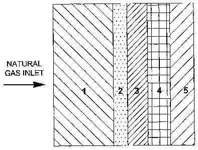
Example 4 (formation of an anode for direct conversion of natural gas)
An SOFC anode for non-reformed natural gas having a graded composition
parallel to
the direction of the gas flow was obtained. The compositions of the layers
were made
such that there was an increased electrochemical activity going from right to
left (gas
inlet to outlet), as illustrated in Figure 4; not all layers are shown for
illustrative pur-
poses.
The compositions of the ten layers were as follows:
Layer 1: STN, Srs(Ti1_yNby)03_6;
Layer 2: 80 vol% STN, 20 vol% CGO, Ce1_,Gdx02-8;
Layer 3: 75 vol% STN, 20 vol% CGO and 5 vol% NiO;
Layer 4: 65 vol% STN, 20 vol% CGO and 15 vol% NiO;
Layer 5: 55 vol% NiO and 45 vol% STN;
Layer 6: 50 vol% NiO and 50 vol% STN;
Layer 7: 45 vol% NiO and 55 vol% STN;
Layer 8: 40 vol% NiO and 60 vol% STN;
16
CA 02638420 2008-07-30
Layer 9: 35 vol% NiO and 65 vol% STN;
Layer 10: 30 vol% NiO and 70 vol% STN.
The tapes were manufactured and laminated as described in Example 1.
Example 5
The anode obtained in Example 4 was built in an electrolyte supported cell.
The
SOFC anode for non-reformed natural gas had a graded composition parallel to
the
direction of the gas flow. The compositions of the layers were made such that
there
was an increased electrochemical activity going from right to left (gas inlet
to outlet),
as illustrated in Figure 4; however, not all layers are shown.
The first step was the manufacture of five screen printing inks having the
composi-
tions as given above.
The second step was the deposition of the layers side by side by screen
printing.
The cell was completed as outlined in Example 3.
Example 6 (SOC cathode ¨ LSM/LSCF)
In order to achieve further balance of the temperature distribution in an SOFC
cell
stack, the electrochemical activity of the cathode is balanced in this
example. In case
of cross flow of the air and fuel in the stack, the temperature in the four
stack corners
will under normal operational conditions be of a lower temperature as compared
to
the center of the stack as follows: T (air out -H2 in) > T (air in - H2 in) >
T (air out-H2
out) >T (air in-H2 out).
The temperature distribution on the cathode side is levelled/controlled by
having a
cross gradient as illustrated in Figure 5; not all layers are shown. The
compositions of
the layers are as follows:
17
CA 02638420 2008-07-30
Layer 1: 50 vol% CGO + 50 vol% LSM 25;
Layer 2: 50 vol% CGO + 38 vol% LSM + 12 vol% LSCF;
Layer 3: 50 vol% CGO + 35 vol% LSM + 15 vol% LSCF;
Layer 4: 50 vol% CGO + 25 vol% LSM + 25 vol% LSCF;
Layer 5: 50 vol% CGO + 22 vol% LSM + 28 vol% LSCF;
Layer 6: 50 vol% CGO + 20 vol% LSM + 30 vol% LSCF;
Layer 7: 50 vol% CGO + 18 vol% LSM + 32 vol% LSCF;
Layer 8: 50 vol% CGO + 15 vol% LSM + 25 vol% LSCF;
Layer 9: 50 vol% CGO + 12 vol% LSM + 38 vol% LSCF;
Layer 10: 50 vol% CGO + 50 vol LSCF.
The tapes are manufactured and laminated as described in Example 1.
Example 7 (SOC cathode ¨ LSM/LSCF)
Further balance of the temperature distribution in an SOFC cell stack may be
achieved by controlling the electrochemical activity of the cathode. In case
of cross
flow of the air and fuel in the stack the temperature in the four stack
corners will under
normal operational conditions be in decreasing order of temperature: T (air
out -H2 in)
> T (air in - H2 in) > T (air out-H2 out) >T (air in-H2 out).
The temperature distribution on the cathode side is levelled/controlled by
having a
cross gradient as illustrated in Figure 5. The compositions of the layers are
as follows:
Layer 1: 50 vol% CGO + 50 vol% LSCF 25;
Layer 2: 50 vol% CGO + 45 vol% LSCF + 5 vol% LSC;
Layer 3: 50 vol% CGO + 38 vol% LSCF + 12 vol% LSC;
Layer 4: 50 vol% CGO + 35 vol% LSCF + 15 vol% LSC;
Layer 5: 50 vol% CGO + 30 vol% LSCF + 20 vol% LSC;
Layer 6: 50 vol% CGO + 28 vol% LSCF + 22 vol% LSC;
Layer 7: 50 vol% CGO + 25 vol% LSCF+ 25 vol% LSC;
Layer 8: 50 vol% CGO + 20 vol% LSCF + 30 vol% LSC;
Layer 9: 50 vol% CGO + 12 vol% LSCF + 38 vol% LSC;
Layer 10: 50 vol% CGO + 50 vol LSC.
18
CA 02638420 2008-07-30
The tapes are manufactured and laminated as described in Example 1 in order to
obtain the SOC cathode.
Example 8 (manufacture of a cell with a circular design)
A SOFC with a circular design for dry or pre-reformed natural gas being
exposed to
the anode was obtained. The inlet of the fuel gas was in the centre of the
cell and the
outlet at the edge. The anode had a graded composition from the inlet to the
outlet.
The compositions of the layers were made such that there was an increased
electro-
chemical activity going from centre to edge (gas inlet to outlet), as
illustrated in Figure
6; not all layers are shown.
Layer 1 consisted of LSCM, (Lal_.SrOs(Cri-yMny)03_8, layer 7 consisted of 80
vor/0 NiO
and 5 vol /0 LSCM; and layer 10 consisted of 100 vol /0 NiO. Layers 2 to 9
consisted of
a linear grading with Layer 6 having a 1:1 ratio. The electrochemical activity
for con-
version of H2 is low for LSCM and high for Ni.
In the first step, seven inks were manufactured. Suspensions for screen
printing were
produced by means of ball milling of powders with polyvinyl pyrrolidone (PVP),
polyvi-
nyl butyral (PVB) and Et0H + MEK as additives. The suspensions were screen
printed onto the cell with the composition varying in a controlled manner from
the cen-
ter and outwards. The layers were subsequently dried.
Ink 1: The suspension comprised LSCM. The green thickness of the printed layer
was
about 40 pm. The porosity of this layer was about 30% after sintering.
Ink 2: The suspension comprised 90 vor/o LSCM and 10 voltY0 NiO. The green
thick-
ness of the printed layer was about 40 pm. The porosity of this layer was
about 30%
after sintering.
Ink 3: The suspension comprised 83 vol /0 LSCM and 17 vol% NiO. The green
thick-
ness of the printed layer was about 40 pm. The porosity of this layer was
about 30%
after sintering.
19
CA 02638420 2008-07-30
Ink 4: The suspension comprised 75 vol% LSCM and 25 vol% MO. The green thick-
ness of the printed layer was about 40 pm. The porosity of this layer was
about 30%
after sintering.
Ink 5: The suspension comprised 66 vol% LSCM and 34 vol% NiO. The green thick-
ness of the printed layer was about 40 pm. The porosity of this layer was
about 30%
after sintering.
Ink 6: The suspension comprised 50 vol% LSCM and 50 vol% NiO. The green thick-
ness of the printed layer was about 40 pm. The porosity of this layer was
about 30%
after sintering.
Ink 7: The suspension comprised 34 vol% LSCM and 66 vol% NiO. The green thick-
ness of the printed layer was about 40 pm. The porosity of this layer was
about 30%
after sintering.
Ink 8: The suspension comprised 17 vol% LSCM and 83 vol% NiO. The green thick-
ness of the printed layer was about 40 pm. The porosity of this layer was
about 30%
after sintering.
Ink 9: The suspension comprised 5 vol% LSCM and 95 vol% NiO. The green thick-
ness of the printed layer was about 40 pm. The porosity of this layer was
about 30%
after sintering.
Ink10: The suspension comprised NiO. The green thickness of the printed layer
was
about 40 pm. The porosity of this layer was about 30% after sintering.
The cell was subsequently sintered at 1150 C in air.
Example 9 (manufacture of a cell with a tubular design)
A tubular or flat-tubular SOFC was obtained, where the composition of the
anode was
graded along the tube. The grading was made such that the composition of the
elec-
CA 02638420 2008-07-30
trode at the inlet was the least reforming active, and with the activity
increasing to-
wards the outlet (other end) of the tube, as illustrated in Figure 7; not all
layers are
shown.
Layer 1 consisted of LSCM, (Lai_xSrx)s(Cri_yMny)03_5, and layer 7 consisted of
95 vol%
NiO and 5 vol% LSCM. Layers 2 to 6 consisted of a linear grading with Layer 4
having
a 1:1 ratio. The electrochemical activity for conversion of H2 is low for LSCM
and high
for Ni.
In the first step, seven slurries were produced. Suspensions for spraying were
manu-
factured by means of ball milling of powders with polyvinyl pyrrolidone (PVP),
polyvi-
nyl butyral (PVB) and Et0H + MEK as additives. The suspensions were sprayed
onto
the tube with the composition varying in a controlled manner along the tube.
The lay-
ers were subsequently dried.
Slurry 1: The suspension comprised LSCM. The green thickness of the sprayed
layer
was about 40 pm. The porosity of this layer was about 30% after sintering.
Slurry 2: The suspension comprised 90 vol% LSCM and 10 vol% NiO. The green
thickness of the sprayed layer was about 40 pm. The porosity of this layer was
about
30% after sintering.
Slurry 3: The suspension comprised 83 vol% LSCM and 17 vol% NiO. The green
thickness of the sprayed layer was about 40 pm. The porosity of this layer was
about
30% after sintering.
Slurry 4: The suspension comprised 75 vol% LSCM and 25 vol% NiO. The green
thickness of the sprayed layer was about 40 pm. The porosity of this layer was
about
30% after sintering.
Slurry 5: The suspension comprises 66 vol% LSCM and 34 vol% NiO. The green
thickness of the sprayed layer was about 40 pm. The porosity of this layer was
about
30% after sintering.
21
CA 02638420 2008-07-30
Slurry 6: The suspension comprised 50 vol% LSCM and 50 vol% NiO. The green
thickness of the sprayed layer was about 40 pm. The porosity of this layer was
about
30% after sintering.
Slurry 7: The suspension comprised 34 vol% LSCM and 66 vol% NiO. The green
thickness of the sprayed layer was about 40 pm. The porosity of this layer was
about
30% after sintering.
Slurry 8: The suspension comprised 17 vol% LSCM and 83 vol% NiO. The green
thickness of the sprayed layer was about 40 pm. The porosity of this layer was
about
30% after sintering.
Slurry9: The suspension comprised 5 vol% LSCM and 95 vol% NiO. The green thick-
ness of the sprayed layer was about 40 pm. The porosity of this layer was
about 30%
after sintering.
Slurry10: The suspension comprised NiO. The green thickness of the sprayed
layer
was about 40 pm. The porosity of this layer was about 30% after sintering.
The tube was then sintered at 1100-1400 C in air.
Example 10 (segmented cell design)
A flat-tubular SOFC design was obtained, where the composition of the anode
was
graded along the segmented-flat-tube cell. The grading was obtained by the
composi-
tion of the individual segments changing from segment to segment such that the
inlet
was the least reforming active, and with activity increasing towards the
outlet of the
module/cell, as illustrated in Figure 8.
Layer 1 consisted of LSCM, (Lai_xSrx)s(Cri_yMny)03.5, and layer 7 consisted of
95 vol%
NiO and 5 vol% LSCM. Layers 2 to 6 consisted of a linear grading with Layer 4
having
a 1:1 ratio.
22
CA 02638420 2008-07-30
The first step was the manufacture of seven inks. Suspensions for screen
printing
were manufactured by means of ball milling of powders with polyvinyl
pyrrolidone
(PVP), polyvinyl butyral (PVB) and Et0H + MEK as additives. The suspensions
were
screen printed onto the cell with the composition varying in a controlled
manner from
the center and outwards. The layers were subsequently dried.
Ink 1: The suspension comprised LSCM. The green thickness of the printed layer
was
about 40 pm. The porosity of this layer was about 30% after sintering.
Ink 2: The suspension comprised 90 vol% LSCM and 10 vol% NiO. The green thick-
ness of the printed layer was about 40 pm. The porosity of this layer was
about 30%
after sintering.
Ink 3: The suspension comprised 83 vol% LSCM and 17 vol% NiO. The green thick-
ness of the printed layer was about 40 pm. The porosity of this layer was
about 30%
after sintering.
Ink 4: The suspension comprised 75 vol% LSCM and 25 vol% NiO. The green thick-
ness of the printed layer was about 40 pm. The porosity of this layer was
about 30%
after sintering.
Ink 5: The suspension comprised 66 vol% LSCM and 34 vol% NiO. The green thick-
ness of the printed layer was about 40 pm. The porosity of this layer was
about 30%
after sintering.
Ink 6: The suspension comprised 50 vol% LSCM and 50 vol% NiO. The green thick-
ness of the printed layer was about 40 pm. The porosity of this layer was
about 30%
after sintering.
Ink 7: The suspension comprised 34 vol% LSCM and 66 vol% NiO. The green thick-
ness of the printed layer was about 40 pm. The porosity of this layer was
about 30%
after sintering.
23
CA 02638420 2008-07-30
Ink 8: The suspension comprised 17 vol% LSCM and 83 vol% NiO. The green thick-
ness of the printed layer was about 40 pm. The porosity of this layer was
about 30%
after sintering.
Ink 9: The suspension comprised 5 vol% LSCM and 95 vol% NiO. The green thick-
ness of the printed layer was about 40 pm. The porosity of this layer was
about 30%
after sintering.
Ink 10: The suspension comprised NiO. The green thickness of the printed layer
was
about 40 pm. The porosity of this layer was about 30% after sintering.
The cell was subsequently sintered at 1150 C in air.
The electrolyte layers, cathode and sealants were afterwards deposited and the
whole assembly sintered in air at 1250 C.
Example 11 (production of a membrane for syngas production with a graded
anode)
A device for the production of synthesis gas was obtained. Methane was fed to
one
side of a membrane, and air to the other. The membrane was a mixed oxide
ion/electronic conductor with a thickness of about 10 micrometer. To provide
sufficient
strength, the membrane was placed on an inert support structure with a
thickness of
several hundred micrometer.
On the side exposed to air an oxygen reduction catalyst layer was applied, and
on the
side exposed to methane, a cracking/steam reforming catalyst was applied. When
in
operation, oxygen permeates from the air side through the membrane to the
methane
side, where a partial oxidation takes placed resulting in generation of a
mixture of CO
and hydrogen. The temperature will change in the direction of the gas-flows as
will the
chemical environment on both sides of the membrane. Hence, it is beneficial to
have
the possibility to vary the composition of the catalyst layers on both sides
of the mem-
brane in the direction of the gas flow as to achieve a local optimisation by
varying the
24
CA 02638420 2008-07-30
composition horizontally to reflect the changing requirements set by the
changing
temperature and the changing chemical environment.
In step 1, a support tape (CGO or MgO) with a thickness of 400 micrometer was
ob-
tamed.
In step 2, a graded structure "anode or catalyst layer" as outlined in example
1 was
produced. Said layer was made by combining 10 tapes of different composition:
Tape 1 comprised 50 vol% support material and 50 vol% Ru-based catalyst
particles;
Tape 2 comprised 50 vol% support material and 45 vol% Ru-based catalyst
particles;
and 5 vol% Ni based catalyst particles;
Tape 3 comprised 50 vol% support particles, 40 vol% Ru based catalyst
particles, and
10 vol% Ni based catalyst particles;
Tape 4 comprised 50 vol% support material and 35 vol% Ru-based catalyst
particles;
and 15 vol% Ni based catalyst particles;
Tape 5 comprised 50 vol% support material, 30 vol% Ru-based catalyst
particles, 20
and vol% Ni;
Tape 6 comprised 50 vol% support material and 25 vol% Ru-based catalyst
particles;
and 25 vol% Ni based catalyst particles;
Tape 7 comprised 50 vol% support material, 20 vol% Ru-based catalyst
particles, and
vol% Ni;
Tape 8 comprised 50 vol% support material and 15 vol% Ru-based catalyst
particles;
and 35 vol% Ni based catalyst particles;
25 Tape 9 comprised 50 vol% support material, 10 vol% Ru-based catalyst
particles, and
vol% Ni;
Tape 10 comprised 50 vol% support material, and 50 vol% Ni.
The tapes were placed on a mylar support and laminated as outlined in Example
1.
In step 3, the catalyst layer tape was laminated together with the
manufactured sup-
port tape.
CA 02638420 2008-07-30
In step 4, the support and catalyst layer tape were laminated with a 25
micrometer
thick membrane tape which was based on CGO.
In step 5 the laminate was sintered at 1300 C for 5 hours.
In step 6, an oxygen reduction catalyst was applied on the membrane surface.
Said
layer was applied by screen printing a slurry of LSC.
In step 7, the cathode was sintered.
When operating the air and methane are fed in co-flow with side comprising the
Ru
catalyst of the membrane at the methane inlet. In the above structure, a more
active
and expensive Ru catalyst is replaced by a cheap Ni catalyst where gas
composition
and temperature allows for said replacement.
Example 12 (Membrane for syngas production with a horizontally graded cath-
ode)
A membrane for the same purpose as described in example 11 and manufactured in
the same way was obtained. However, for the cathode application, a horizontal
grad-
ing is achieved such that the composition changes in the direction of the air
flow. At
the inlet La02Sr0.8Co03 is used, and down stream the air side materials with
less and
less Sr doping are applied.
Example 13 (Membrane for oxygen production with a horizontally graded elec-
trode)
A membrane for oxygen production operating at high temperature between pressur-
ized air and a pure oxygen permeate stream was obtained. The electrode composi-
tion varies down stream of the pressurized air such that the Sr content is
gradually
reduced going down stream the pressurized air 1) SrCo02.5, 2) La0.3 Sr0.7C003
, 3)
La0.8Sr0.4Co03. The membrane was obtained as described in example 11.
26
CA 02638420 2008-07-30
Example 14 (Supported membrane with graded composition in the membrane
(co-firing route))
A membrane with a composition gradient in the gas flow direction was obtained.
At
the methane inlet La0.6Sr0.4Fe0.8Cr0.203 was used. In the middle section,
(La,Sr)Fe03
and in the outlet section, (La,Sr)Fe0.8Co0.203was applied.
In the first step, the support tape was obtained.
In the second step, the catalyst, a Ru based supported catalyst was tape cast.
Step 3 was the manufacture of a graded tape for later lamination. Tape 1
consisted of
La0,6Sr0.4Fe0.8Cr0,203, tape 2 consisted of La0.6Sr0.4Fe0.9Cr0.103, tape 3
consisted of
La0.6Sr0.4Fe03, and tape 4 consisted of La0.6Sr0,4Fe0.9Co0.103.
Step 4 was the lamination of the obtained tapes on each other.
Step 5 was the sintering of the obtained laminate.
In step 6, the cathode was applied on the sintered structure so as to obtain
the mem-
brane. The obtained membrane design is especially suitable for use in a
counter flow
device. Methane enters (and air exits) at the LSFCr side (hot and very
reducing). Syn-
gas exits and air is fed at the LSFeCo side (cold but less reducing).
Example 15 (Supported membrane with stepwise change in the membrane com-
position, screen printing)
A device was obtained as described in example 11, with the exception that the
mem-
brane composition changes stepwise and the membrane layers are made by screen
printing.
Step 1 was the manufacture of a MgO support by extrusion or tape casting.
In step 2, the support was sintered for two hours at about 1300 C.
27
CA 02638420 2008-07-30
In step 3, the catalyst was applied by dip coating the support in a very thin
slurry com-
prising ultrafine catalyst particles in form of a suspension.
Step 4 was the application of membrane layers in a sequence of printings,
where first
of all, the upstream segment was printed, consisting of
(La0.6Sr0.4Fe0.8Cro.203), and
subsequently four more segments were printed such that a small overlap at the
bor-
der between neighbouring segments is ensured. The composition varied from seg-
ment to segment in the same manner as outlined in example 11.
In step 5, the component was sintered at 1325 C for four hours.
In step 6, a porous catalyst layer was applied on top of the membrane layer by
spray-
ing so as to obtain the supported membrane.
Example 17 (Supported membrane with stepwise change in the membrane com-
position, vacuum plasma spraying)
The membrane was obtained as outlined for example 15, with the exception that
step
4 is replaced by a membrane application step by vacuum plasma spraying. The
grad-
ing is achieved using several guns connected to different feeds.
Example 18 (Patterned and graded corrosion protection coating manufactured
by "ink jet printing")
To achieve long term durability, ferritic Fe/Cr steels used as interconnects
must be
provided by suitable protective coatings. Both (La,Sr)Co03 and A1203 are
excellent
protection material for prolonging the lifetime of steels like Crofer22APU. In
a stack
where electrical contact is only needed over a fraction of the area it is
desirable to
apply an A1203 rich coating over the none current carrying areas and an
(La,Sr)Co03
rich coating over the current carrying areas. A corrugated plate is considered
where
the cross section has the shape of a sinusoidal.
28
CA 02638420 2008-07-30
The plate is provided with a protective coat applied in strips (See Fig. 9).
At the wave
tops where contact is established to the cathode a coating of A1203 20 % and
(La,Sr)
Co03 80% was applied by printing (layer A, Fig 9). At the "bottom of the
waves" (non
current carrying area) a 80% A1203 and 20 % (La,Sr)Co03 coating was applied by
printing (layer B, Fig. 9) using an ink-jet-type printing device specially
suited for appli-
cation of particulate slurries of the type described here. The jet was fed
from two dif-
ferent cartridges containing the two slurries here preferred. The coat was
applied in a
line to line printing operation where the feed changes whenever jet moves in
and out
of the contact zones (see Figure 9).
Example 19 (Graded corrosion protection coating manufactured by air spray-
ing)
The temperature in a stack varies in the air flow direction, as outlined
above. This re-
sults in the air exit region being the most critical for corrosion protection.
In this exam-
ple, the interconnect is protectedby a sprayed coating where the composition
varied
from A1203/(LaSr)Co03 50/50 in the outlet region to (LaSr)Co03 in the inlet
region.
The grading was achieved by spraying from multiple containers as outlined
above for
Example 1. Figure 10 illustrates the obtained structure.
29