Note : Les descriptions sont présentées dans la langue officielle dans laquelle elles ont été soumises.
CA 02638696 2012-08-30
LED WARNING LIGHT
Technical Field
[0001] The disclosure relates to a warning light and, more particularly, to
a warning light utilizing light emitting diodes (LED) to generate warning
light
signals for use in conjunction with emergency vehicles.
Background
[0002] Emergency vehicles are commonly provided with warning lights
mounted to the exterior of the vehicle in the form of beacons and light bars.
It
is also known to provide emergency vehicles with warning lights mounted inside
the vehicle to project warning light signals through the windshield or rear
window. Further, warning lights have been mounted in the original equipment
reflector shells for the front corner, taillight and reverse lights. The
standard
practice is to drill a hole in the enclosure and mount a halogen bulb or
strobe
tube in the enclosure. When power is applied to these warning lights, light
fills
the vehicle reflector and generates warning light signals.
[0003] Advances in LED brightness allow LEDs to replace halogen bulbs
and gaseous discharge strobe tubes to generate warning light signals.
Summary
[0004] The disclosed LED warning lights include a compact lighthead
configured for mounting in the original equipment reflector shell of a motor
vehicle. Each lighthead includes a base and cover which define an interior
space sealed against the elements. The base is constructed of thermally
conductive material and includes at least one planar surface to which LED
lamps
are mounted. The cover is constructed of light transmissive plastic material
and
configured to mate with complementary structures on the base. The cover is
configured to fit through an opening in the reflector shell such that light
1
CA 02638696 2012-08-30
generated by the LED lamps is emitted into the reflector shell and directed
outwardly through the lens of the motor vehicle light.
[0005] Subsets of the LED lamps are electrically connected in series to
form a plurality of LED arrays. Each LED array is provided with its own
constant
current source. A controller applies timed pulses of electrical current to the
arrays to produce warning light signals. The controller is responsive to a
pattern select input to select the generated warning light signal from a
plurality
of patterns stored in memory. A synchronization input to the controller allows
the signals generated by multiple lightheads to be coordinated.
[0006] In one embodiment, each array of LED lamps is arranged on a
planar PC board mounted to one side of a shaft in the form of a regular
polyhedron. The arrays of LED lamps may be of the same or different colors
and may be activated simultaneously or in groups to produce light signals of
different colors. An alternative embodiment includes a surface texture on the
portion of the cover through which light generated by the LED lamps will pass.
The surface texture blends and diffuses light from the LED lamps to illuminate
the cover and obscure the internal features of the lighthead during operation.
[0007] According to one aspect of the present invention there is provided
an LED warning light comprising: a base of thermally conductive material
including at least one substantially planar surface; a plurality of LED lamps
arranged in thermally conductive relationship to the planar surface, the LED
lamps electrically connected to form a plurality of series arrays and each the
LED lamp having an optical axis and generating a substantially symmetrical
pattern of light emission surrounding the axis when electrical energy is
applied
to the lamp; a light transmissive cover configured to mate with the base to
define an enclosed space surrounding the plurality of LED lamps, the cover
having inside and outside surfaces, wherein at least one of the inside or the
outside surfaces includes a surface texture and light from the LEDs incident
2
CA 02638696 2012-08-30
upon the surface texture is diffused, and each the series array having a power
source independent of the other the series arrays.
[0007.1] According to a further aspect of the present invention there is
provided an LED warning light comprising: a base of thermally conductive
material including at least one substantially planar surface; a plurality of
LED
lamps arranged in thermally conductive relationship to the planar surface, the
LED lamps electrically connected to form at least one array and each the LED
lamp having an optical axis and generating a substantially symmetrical pattern
of light emission surrounding the axis when electrical energy is applied to
the
lamp; a light transmissive cover configured to mate with the base to define an
enclosed space surrounding the plurality of LED lamps, the cover having inside
and outside surfaces, wherein at least one of the inside or the outside
surfaces
includes a surface texture and light from the LEDs incident upon the surface
texture is diffused, and the base includes a shaft and the substantially
planar
surface comprises a plurality of substantially planar surfaces formed on the
outside of the shaft.
Brief Description of the Drawings
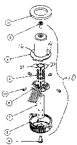
[0008] Figure 1 is an exploded view of an embodiment of an LED warning
light according to aspects of the disclosure;
[0009] Figure 1A is a top plan view of the post and LED arrays of the LED
warning light of Figure 1, showing the patterns of light emission;
[0010] Figure 2 is bottom perspective view of the cover shown in Figure
1;
2a
CA 02638696 2008-08-15
[0011] Figure 3 is a bottom plan view of the cover of Figure 2;
[0012] Figure 4 is a top perspective view of the base shown in Figure 1;
[0013] Figure 5 is a block diagram of a representative warning signal light
system including six of the disclosed LED warning lights;
[0014] Figure 6 is a perspective view of a second embodiment of an LED
warning light according to aspects of the disclosure;
[0015] Figure 7 is an exploded view of the LED warning light of Figure 6;
[0016] Figure 8 is a bottom perspective view of a lens for the LED
warning light of Figure 6;
[0017] Figure 9 is a top perspective view of a base for the LED warning
light of Figure 6;
[0018] Figure 10 is a bottom perspective view of the lens, base, and cable
for the LED warning light of Figure 6; and
[0019] Figure 11 is a schematic block diagram of the LED warning light
and dedicated power supply of Figures 6-10.
Detailed Description
[0020] The disclosed LED warning lights are configured for mounting in
the reflector shell for front corner, taillight and reverse lights of a
motorized
vehicle. Such warning lights may be referred to as Hide-A-Way warning lights.
A first embodiment of the disclosed LED warning light is designated by the
reference numeral 10 and includes a base 5 and mating cover 6 which together
define an interior space enclosing a plurality of LED arrays 4. Each LED array
4
includes one or more LEDs mounted to a thermally conductive PC board. The
PC board may be a metal core board or other PC board provided with thermally
conductive features. The LED arrays are typically planar. The warning light
includes a shaft 7 of thermally conductive material, such as aluminum or die
cast metal.
[0021] In LED warning light 10, the shaft 7 is square in section and is
secured to the base 5 by a screw 8. Alternatively, the shaft may be molded
3
CA 02638696 2008-08-15
(cast) integrally with the base 5. The shaft 7 and base 5 are configured to
support the LED arrays 4 and conduct heat away from the LEDs to an area
outside the vehicle reflector shell. The base 5 is provided with fins to
increase
the radiant surface area and improve cooling. Other shaft configurations are
possible, with typical sectional shapes in the form of a regular polygon such
as a
triangle, square, pentagon hexagon, etc. The sides of the disclosed shaft 5
are
parallel and the sectional shape of the shaft 5 is constant along its length.
Alternative configurations where the sides are not parallel and the sectional
shape of the shaft varies along its length may be compatible with the
disclosed
LED warning lights.
[0022] The cover 6 is secured to the base by a screw 8 engaging an outer
(distal) end of the shaft 7. The base 5 and cover 6 each include complementary
cable openings (wire channels) 19, 17, respectively configured to surround
electrical wires extending out of the warning light 10. The cover 6 and base 5
include mating lip structures 13 (cover), 15 (base) at the periphery of their
connection not occupied by the cable openings 17, 19. As shown in Figure 3,
the upper inside portion of the cover 6 defines four pairs of ribs 26 arranged
to
compress the upper ends 27 of the LED arrays 4 against the upper end of the
shaft when the cover is installed. The LED arrays 4 are also compressed
against
the shaft by fasteners 12. Maintaining face-to-face contact between the LED
arrays 4 and the shaft 5 promotes efficient heat transfer.
[0023] The cover 6 also defines two openings 14, 16 communicating with
the interior space defined by the cover 6 and base 5. These openings 14, 16
are used to fill the base 5 with encapsulant after the warning light has been
assembled. Encapsulant (not shown) is injected into the larger of the two
holes
14 while air escapes from the interior space through the smaller of the two
holes 16. The base is filled with encapsulant to a level covering the
horizontal
PC board 9 and sealing the cable openings from the inside. Encapsulant is
filled
to the level of the holes 14, 16 at the bottom of the cover 6. The encapsulant
4
CA 02638696 2008-08-15
seals the cable openings and seals the base 5 to the cover 6 as well as
filling the
openings 14, 16 in the cover 6 to provide a sealed enclosure.
[0024] In LED warning light 10, each LED array 4 is provided with its own
electrical power. With reference to Figure 5, each of the four LED arrays has
its
own power wire and is connected to a common ground. The disclosed cable
openings (wire channels) 17, 19 provide paths for five conductors, one power
lead for each array and a common ground. In a typical installation, the five
wires leaving an LED warning light will terminate in a plug which will mate
with
a corresponding plug or socket connected to a jacketed cable having five
conductors connected to a power supply 22. This arrangement permits a
controller 20 in the power supply 22 to activate each LED array individually
and
removes heat generating components such as current sources 24 from within
the closed space defined by the cover 6 and base 5. In some configurations,
two of the LED arrays 4 will have LEDs of a first color and the other two of
the
LED arrays 4 will have LEDs of a second color. For example, two of the arrays
4
may be red and two of the arrays may be blue. The arrays of the same color
may be opposite or adjacent each other. A controller 20 may be configured to
activate the LED arrays of the first color in an alternating pattern with the
LED
arrays of the second color to provide a dual color light signal.
Alternatively, for
certain signals one color may be used, while the other color may be employed
for other signals.
[0025] In the disclosed system, the LED warning lights are driven by one
or more remote power supplies 22 configured with current sources 24 for each
LED array 4. Larger current sources could be employed to drive more than one
array connected in parallel. Providing each LED array 4 with its own current
source and power lead (wire) provides a safeguard against component failure.
For example, if an LED or current source fails, only one LED array 4 will be
extinguished in the disclosed configuration. The power supply 22 may be
configured to sense such failure and provide some indication to those
responsible for maintaining the emergency vehicle. The indication may take the
5
CA 02638696 2008-08-15
form of a visual indicator on the power supply, such as a lit or extinguished
LED.
Alternatively, the power supply 22 controller 20 may be programmed to alter
the warning light signal generated by the LED warning light experiencing the
failure or may be programmed to extinguish the LED warning light in question
to provide some positive indication of a problem.
[0026] The power supply will include a controller 20, typically in the form
of a microprocessor programmed to apply power to the LED arrays 4 individually
or more typically to all the arrays in a warning light simultaneously to
produce
light signals. The power supply may have two, four or six outlets. Typical
installations will include LED warning lights in the front corners, taillights
and/or
backup light reflector shells (not shown). The power supply 22 controller 20
is
programmed to coordinate the light signals generated by connected LED
warning lights 10.
[0027] The LED arrays 4 are arranged around the shaft 7 to emit light in
a 360 pattern inside the enclosure. In most, if not all, installed
orientations of
the LED warning light 10, some of the LED arrays 4 will be oriented to emit
light
directed at the reflecting surfaces of the enclosure, while other LED arrays 4
will
be oriented to emit light directed through the lens of the enclosure. The
disclosed LED warning lights 10 fill the reflector to provide a large
illuminated
surface area and also produce bright illumination directly through the lens of
the
enclosure. The resulting illumination pattern is very similar to prior art
gaseous
discharge tubes, with the advantages of LED durability, colored light emission
and power efficiency.
[0028] Each of the disclosed LED arrays 4 include three LUXEON Rebel
LED lamps, each having a typical luminous flux of approximately 100Im
(lumens) at a drive current of approximately 350mA. In this configuration,
each
LED warning light produces approximately 12001m, or approximately 801m per
watt of applied power. The selected LEDs may be white LEDs or LEDs of a
selected color. The cover may be tinted to filter light generated by white
LEDs,
6
CA 02638696 2008-08-15
for example to an amber/yellow color. Other LED lamps may be compatible
with the disclosure.
[0029] The disclosed LUXEON Rebel LEDs have a wide angle pattern of
light emission with a total included angle BT of approximately 1600 and a
viewing angle 81/2 of approximately 70 . The total included angle OT is the
angle, centered on the optical axis of the LED lamp, within which 90% of the
luminous flux produced by the lamp is emitted. The viewing angle 81/2 is the
angle with respect to the optical axis Ao of the LED lamp at which the
luminous
intensity of the light pattern is 1/2 of the peak value. The peak luminous
intensity of an LED lamp having a lambertian light pattern is typically at or
near
the optical axis Ao. As shown in Figure 1A, the light emission pattern from
each
LED array 4 overlaps that of an adjacent LED array 4 at B to produce a pattern
of light emission surrounding the shaft 7.
[0030] The cover 6, shaft 7 and LED arrays 4 of the disclosed LED
warning light 10 are configured to minimize the size of the hole needed for
installation. Each of the arrays is approximately .28" - .3" wide, with each
face
of the shaft having a corresponding width. The disclosed LED warning light 10
requires a hole .75" in diameter. This configuration also minimizes any
disruption of the light pattern generated by the vehicle signal lights used
for
running lights, turn signal lights and brake light signals. A gasket 11 is
positioned between the flared base portion of the LED warning light 10 and the
reflector enclosure when the LED warning light is installed to an enclosure to
prevent intrusion of moisture and other contaminants. The flared base portion
of the LED warning light remains outside the reflector enclosure, while the
cover
6, shaft 7 and LED arrays 4 project into the space defined by the reflector
shell.
[0031] An alternative embodiment of a LED warning light, designated by
reference numeral 30, is illustrated in Figures 6 through 10. With specific
reference to Figures 7 and 9, alternative LED warning light 30 employs a base
32 and dome-shaped cover 33 which mate to define an interior space. The LED
7
CA 02638696 2008-08-15
=
warning light 30 also includes a power supply 60 integrated into the power
cable 40.
[0032] The base 32 is configured with a circular boss 34
extending
upwardly from a flange 36 to a ring-shaped planar top surface 37. The circular
boss 34 is configured with a central aperture 38 to admit a power cable 40.
The
base 32 is constructed of thermally conductive material such as die cast metal
or thermally conductive plastic or thermally conductive composite material. A
PC board 42 having a generally circular configuration is configured for
mounting
to the top surface 37 of the boss 34 by means of two screws, as shown in
Figure 7.
[0033] Six LED lamps 44 are mounted on the PC board 42 in two
arcuate
arrays 46 each array including three LED lamps 44. The three LED lamps 44 in
each array 46 are electrically connected in series and receive power from the
power cable 40 via traces on the PC board 42. The PC board 42 may be a
standard fiber board material known as FR4 provided with a pattern of copper
plated thermal vias (not shown) beneath each LED lamp 44 as is known in the
art. Alternatively, the PC board 42 may be a metal-core PC board. The LED
lamps 44 are positioned on the PC board 42 and provided with thermal vias to
efficiently conduct heat away from the LED lamps 44 to the ring shaped boss 34
and the rest of the base 32. The LED lamps 44 are LUXEON Rebel LED lamps
and may be selected from a variety of available colors or power ratings,
depending upon the desired warning light signal and light emission pattern.
[0034] As best seen in Figure 9, the base 32 includes a flange
36
projecting radially from the bottom of the ring shaped boss 34. The upper
surface of the flange 36 defines a circular groove 48 around the boss 34. The
cover 33 has a dome shape, the upper portion 31 of which is substantially
hemispherical as shown in Figures 6-8 and 10. The cover 33 is configured to
surround the boss 34 and provide an enclosed space over the PC board 42 and
LED lamps 44. The bottom of the cover 33 is configured to mate with
complimentary features defined by flange 36 of the base 32. The bottom8
CA 02638696 2008-08-15
surface of the cover 33 also includes a circular projection 50 configured to
mate
with the groove 48 surrounding the boss 34. The cover also includes
diametrically opposed latches 52 which mate with complimentary receptacles 54
defined by the base 32 to secure the cover 33 to the base 32.
[0035] During assembly, the PC board 42 with its attached power cable
40 is secured to the top surface 37 of the ring-shaped boss 34 using two
screws. A thermally conductive gasket material (not shown) may be interposed
between the bottom surface of the PC board 42 and the top surface 37 of the
boss 34 as is known in this field. A ring of sealant material (not shown) is
extruded into the groove 48 surrounding the boss 34. The cover 33 is then
mated with the base 32. The circular projection 50 from the bottom of the
cover
penetrates the groove 48, contacting the sealant, while the latches 52 on the
cover snap into the receptacles 54 defined by the base to retain the cover 33
in
mated position while the sealant cures. The cover 33 and sealant prevent
moisture penetration between the base 32 and cover 33 around the boss 34.
[0036] With reference to Figure 9, the bottom side of the base 32
includes raised fins configured to increase the radiant surface area of the
base
32 and enhance cooling. The central portion of the bottom side of the base 32
is bounded by a raised ring 56. After the PC board 42 and the attached power
cable 40 are secured to the base 32, the base is positioned with the bottom
side
facing upward and the area bounded by the raised ring 56 is filled with
encapsulant material (not shown). Encapsulant fills the opening 38 surrounding
the power cable 40 and the holes which receive the PC board mounting screws.
Once cured, the encapsulant prevents moisture penetration and provides strain
relief for the power cable 40. The disclosed configurations and procedures
provide a lighthead 35 that is sealed against the environment.
[0037] With reference to Figure 11, the power cable 40 extends from the
lighthead 35 to a dedicated power supply 60. The power cable 40 includes a
common ground and a power lead (wire) for each array of LED lamps 46. The
power supply 60 structure includes a housing 62, PC board 64 and a cover 66.
9
CA 02638696 2008-08-15
The PC board 64 includes a controller 61 and two current sources 63, one
current source 63 for each array 46 of three series-connected LED lamps 44 in
the light head 35. The controller 61 is preferably a microcontroller having on
board memory and programmed to apply timed power pulses to the arrays 46
of LED lamps 44 to produce warning light signals. An input cable 65 delivers
vehicle power, vehicle ground and several input signals to the power supply
60.
The input signals include a synchronization signal SYNC, and a pattern select
input. The SYNC signal is an input to the microcontroller 61 allowing the
activity
of multiple dedicated power supplies 60 to be coordinated to produce
synchronized warning light signals. The microcontroller 61 is also responsive
to
a pattern selection input to select the pattern generated by the lighthead 35
from a plurality of patterns stored in memory as is known in the art. The
selected pattern is stored in memory and is generated when vehicle power is
applied to the dedicated power supply 60 via an on/off switch.
[0038] The electrical configuration of the dedicated power supply 60 is
similar to that of the remote power supply 22 discussed above in that the
plurality of LEDs in each lighthead are divided into series connected arrays
4,
46, each provided with its own current source 24, 63. The current sources 24,
63 are responsive to the microcontroller 20, 61 to deliver power to the LED
arrays 4, 46.
[0039] The cover 33 may be clear or colored as desired. Light generated
by the LED lamps 44 will pass through the upper, hemispherical-shaped portion
31 of the cover 33. The upper portion 31 of the cover 33 may be optically
transparent or may include optical features to spread or distribute light
according to the desired radiation pattern. One feature which has proven
desirable is to provide a frosted surface texture to the inside surface 39 of
the
upper portion 31 of the cover 33. The relevant surface of the mold from which
the cover 33 is produced is exposed to a dry grit blast treatment to provide a
light surface texture on the corresponding inside surface of the upper portion
32
of the cover 33. One suitable texture is composed of randomly oriented
10
CA 02638696 2008-08-15
features having a depth of approximately .00004" or about one micron (pm).
Such randomly oriented textures may be produced by a variety of methods
including EDM, dry grit (or glass bead) blasting or chemical treatments such
as
etching. The objective of the disclosed texture is to produce a plastic part
which
diffuses a small amount of the light emitted by the arrays of LEDs and
illuminate
the upper portion 31 of the cover 33 during warning light operation. Deeper or
more aggressive textures, in excess of approximately 10 pm or about .0004"
will
typically produce undesirable scattering and internal reflection, which could
reduce the overall luminous efficiency of the disclosed LED warning lights 10,
30.
[0040] In an exemplary embodiment, a mold for the cover 33 is machined
from P20 tool steel, the surface of which is finished to an S.P.I. C-2 to C-3
finish
to remove any tool marks. The mold is then heat treated to a hardness of 28-
32 on the Rockwell Re scale. The portion of the mold corresponding to the
inside surface of the upper portion 31 of the cover 33 is then exposed to a
dry
grit blast treatment using #220-240 aluminum oxide grit to produce an S.P.I. D-
2 finish. One corresponding industry standard is specified by Detroit Mold
Engineering with the reference "D-M-E S.P.I. #D-2." An S.P.I. D-2 finish on
the
mold produces a part having a "frosted" or matte surface finish. The remaining
portions of the mold are polished to an S.P.I. A-2 finish, which results in a
smooth, shiny surface on the molded part.
[0041] Alternatively, the textured surface portions may be provided by
electric discharge machining ("EDM") a corresponding section of the mold with
an electric discharge machine. EDM is a process that involves applying a
potential difference between an electrode and an electrically conductive
workpiece to cause electric discharge therebetween. The impact of the
discharge against the workpiece causes the workpiece to be machined.
Different roughnesses may be achieved by varying certain operating
parameters, such as the electrode material, the magnitude and time-
dependence of the electric potential, as well as the electrode-workpiece
11
CA 02638696 2012-08-30
distance. An EDM machine finish compatible with the textured portion of the
cover for the disclosed LED warning lights is "CHARMILLES CH-28."
[0042] One measure of surface texture is Roughness Average Ra.
Roughness average Ra, also known as arithmetic average (AA) and centerline
average (CLA), is the arithmetic average of the absolute values of the
measured
profile height deviations taken within the sampling length and measured from
the graphical centerline. This type of measurement can be taken by an
instrument called a profilometer. The roughness average Ra of a surface
texture
compatible with the disclosed LED warning lights is between approximately 10
and 40 micro inches or between approximately .25 and 1 pm (micron) and more
preferably between 20 and 30 micro inches (.5 pm and .75pm).
[0043] Light from the LED lamps striking the textured surface of the cover
is diffused, causing the upper (hemispherical) portion 31 of the cover 33 to
be
illuminated. Illuminating the upper (hemispherical) portion 31 of the cover 33
gives the illusion that light is emanating from the upper portion 31 and
blends
the light from the six LED lamps 44. When energized, this effect obscures the
internal structures of the lighthead 35. Similar surface treatments may be
employed on the cover 6 of the embodiment of the LED warning light
designated in this application by reference numeral 10 and illustrated in
Figures
1-5.
[0044] In a typical vehicle installation, a hole is prepared in the reflector
shell of an original equipment vehicle light (not shown). The lighthead 10, 35
is
secured to the reflector shell with self tapping screws (shown in Figure 6)
with
the cover 16, 33 protruding into the vehicle light enclosure. A gasket 11, 70
is
placed between the lighthead 10, 35 and the reflector shell to prevent
moisture
penetration into the reflector shell.
[0045] It will be appreciated that various of the above-disclosed and other
features and functions or alternatives thereof, may be desirably combined into
many other different systems, devices or applications. The scope of the claims
should not be limited by the preferred embodiments set forth in the examples,
12
CA 02638696 2012-08-30
but should be given the broadest interpretation consistent with the
description
as a whole.
13