Sélection de la langue

Search

Sommaire du brevet 2639782 

Énoncé de désistement de responsabilité concernant l'information provenant de tiers

Une partie des informations de ce site Web a été fournie par des sources externes. Le gouvernement du Canada n'assume aucune responsabilité concernant la précision, l'actualité ou la fiabilité des informations fournies par les sources externes. Les utilisateurs qui désirent employer cette information devraient consulter directement la source des informations. Le contenu fourni par les sources externes n'est pas assujetti aux exigences sur les langues officielles, la protection des renseignements personnels et l'accessibilité.

Disponibilité de l'Abrégé et des Revendications

L'apparition de différences dans le texte et l'image des Revendications et de l'Abrégé dépend du moment auquel le document est publié. Les textes des Revendications et de l'Abrégé sont affichés :

  • lorsque la demande peut être examinée par le public;
  • lorsque le brevet est émis (délivrance).
(12) Demande de brevet: (11) CA 2639782
(54) Titre français: BORNIER SANS VIS POUR FILS ELECTRIQUES
(54) Titre anglais: SCREWLESS TERMINAL FOR ELECTRICAL LEADS
Statut: Réputée abandonnée et au-delà du délai pour le rétablissement - en attente de la réponse à l’avis de communication rejetée
Données bibliographiques
(51) Classification internationale des brevets (CIB):
  • H01R 04/48 (2006.01)
  • H01H 71/08 (2006.01)
  • H01H 73/20 (2006.01)
  • H01R 43/00 (2006.01)
(72) Inventeurs :
  • PIJOAN-PARELLADA, JOSEP (Espagne)
  • CALLEJA, EDUARDO (Espagne)
  • DESHMUKH, RANJIT MANOHAR (Inde)
  • GURURAJ, RANGANATH (Inde)
  • MURTHY, VENKATESHA (Inde)
(73) Titulaires :
  • GENERAL ELECTRIC COMPANY
(71) Demandeurs :
  • GENERAL ELECTRIC COMPANY (Etats-Unis d'Amérique)
(74) Agent: CRAIG WILSON AND COMPANY
(74) Co-agent:
(45) Délivré:
(22) Date de dépôt: 2008-09-25
(41) Mise à la disponibilité du public: 2009-04-10
Requête d'examen: 2013-07-25
Licence disponible: S.O.
Cédé au domaine public: S.O.
(25) Langue des documents déposés: Anglais

Traité de coopération en matière de brevets (PCT): Non

(30) Données de priorité de la demande:
Numéro de la demande Pays / territoire Date
11/869,984 (Etats-Unis d'Amérique) 2007-10-10

Abrégés

Abrégé anglais


According to a preferred embodiment, a terminal for electrical leads
comprises a housing (1), a guide (4), a current bar (3), a leaf spring and a
moveable
operator (2). The guide (4) is supported by the housing (1) and comprises
guide
surfaces that connect with at least one surface of the current bar (3). The
leaf spring
comprises at least one limb (42) with an offset for clamping a cable to the
current bar
(3). Additionally, the terminal comprises a moveable operator (2) dimensioned
and
configured to allow the release of a cable from contact with the current bar
(3).

Revendications

Note : Les revendications sont présentées dans la langue officielle dans laquelle elles ont été soumises.


CLAIMS:
What is Claimed is:
1. A terminal for electrical leads comprising:
a housing (1);
a guide (4) supported by the housing (1) and comprising guide surfaces;
a current bar (3) interconnected with the guide (4) and comprising at least
one contact surface;
a leaf spring comprising at least one limb biased proximal to the at least
one contact surface; and
a moveable operator (2) dimensioned and configured to engage the leaf
spring whereby the at least one limb moves in a direction distal to the
contact surface.
2. The terminal of claim 1, wherein the guide (4) is comprises two
surfaces configured to direct the operator (2) to the spring leaf.
3. The terminal of claim 1, wherein the terminal comprises a flange (20)
that anchors to the housing (1).
4. The terminal of claim 1, wherein the leaf spring is comprises at least
one clamping limb with a single, curved flange (20) for contact with the
operator (2).
5. The terminal of claim 4, wherein the leaf spring is comprises two
clamping limbs (42).
6. The terminal of claim 1, wherein the fixed terminal and leaf spring are
formed together.
7. The terminal of claim 1, wherein the operator (2) comprises wing-like
projections that guide (4) the operator (2) to move in a vertical direction.
6

8. The terminal of claim 1, wherein the housing (1) consists of a circuit
breaker casing.
9. The terminal of claim 1, wherein the fixed terminal and guide (4) are
formed as one piece.
7

Description

Note : Les descriptions sont présentées dans la langue officielle dans laquelle elles ont été soumises.

CA 02639782 2008-09-25
224996
SCREWLESS TERMINAL FOR ELECTRICAL LEADS
BACKGROUND OF THE INVENTION
Field of the Invention
The subject matter described herein relates generally to a device for
screwless fitting of terminal leads in electrical applications, more
particularly in
circuit breakers.
Related Art
Terminals for electrical leads are typically found in various applications
including switches and circuit breakers.
Prior art methods of connecting lead wire to the circuit breaker required
screwing the wire to the terminal, which resulted in a loss of efficiency.
More
particularly, it increased the amount of installation time required for
connecting wire
to circuit breakers. Therefore, screwless terminals such as the one described
in US
7,224, 140 comprise spring clips that hold electrical leads to the terminal.
The spring
clips are comprises various shapes including U shapes and are made of flexible
material. Currently, a simplified insertion and release mechanism is lacking
to
connect both flexible and/or hard wires to a terminal.
Accordingly, there is a need to provide an improved terminal for electrical
leads to provide for a more efficient installation of devices such as circuit
breakers.
SUMMARY OF THE INVENTION
According to one embodiment, a terminal for electrical leads comprises a
housing, a guide, a current bar, a leaf spring and a moveable operator. The
guide is
supported by the housing and comprises guide surfaces that connect with at
least one
surface of the current bar. The leaf spring comprises at least one limb with
an offset
1

CA 02639782 2008-09-25
224996
for clamping a cable to the current bar. Additionally, the terminal comprises
a
moveable operator dimensioned and configured to allow the release of a cable
from
contact with the current bar.
BRIEF DESCRIPTION OF THE DRAWINGS
The drawings are described herein:
Figure 1 is a perspective view of a modular electric device as per the
invention, has a screwless cable terminal arrangement.
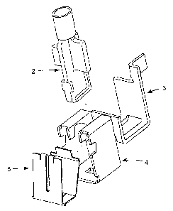
Figure 2 is an exploded view of the screwless cable terminal components.
Figure 3 is a perspective view of the guide.
Figure 4 is a perspective view of the current bar.
Figure 5 is a perspective view of the leaf spring.
Figure 6 is a perspective view of the operator.
Figure 7 is a perspective view of the one embodiment of the invention during
cable inserting condition.
DETAILED DESCRIPTION OF THE INVENTION
One embodiment of the present inventions concerns a screwless terminal
arrangement for connecting rigid or flexible electric wires to a circuit
breaker.
Referring now to figure 1, a circuit breaker in accordance with one
embodiment of the present invention is illustrated generally at 10. The
circuit breaker
is shown as having an insulation housing I containing an operating element 2.
The
insulation housing I is provided with at least one terminal compartment 4, in
which is
disposed a current bar 3, and a clamping spring 5.
In one embodiment of the invention, the housing is constructed of an
injection-molded polymer. Additionally, the housing comprises a rectangular
shape
2

CA 02639782 2008-09-25
224996
with a cavity for holding the components of the circuit breaker 10. The
housing
contains a surface with an aperture to allow the push-in surface of the
operator 2 to
project out of the housing to enable an installer to press it in order to
insert or release
a cable from the hold of the leaf spring. Similarly, the housing has a surface
with an
aperture for insertion of the cable into the circuit breaker that is
perpendicular to the
surface wherein the aperture for the operator is located. The surface
comprises a
single aperture 6 that allows the insertion of one cable into the circuit
breaker.
Alternately, the surface comprises two separate apertures that can receive a
single
cable each. The housing further contains a flat surface area within the cavity
of the
housing onto which the terminal flange 20 will anchor. Furthermore, the
housing
cavity has a base surface that supports the guide 4.
Referring now to figure 2, the components of the screwless terminal are
shown in an exploded view.
Referring now to figure 3, the guide or terminal compartment 4 is shown.
The terminal compartment 4 acts as a support and/or guide for the electric
wires that
are inserted through the housing 1. The guide has two outer surfaces 30 that
are
configured to interlock with the two surfaces of the current bar 3. The outer
surfaces
guide the operator to the leaf spring. The base surface has an aperture for
holding
with the leaf spring. The guide can be made of any resilient material and is
substantially rectangular in shape.
Referring now to Figure 4, the current bar 3 is shown. The current bar is a
component that forms a current path from an externally inserted wire to the
inner
portion of the circuit breaker. The current bar has surfaces 21 for connecting
to the
electric wire. One embodiment of the invention includes a current bar that is
substantially rectangular in shape with the base having an aperture through
which the
operator moves to make contact with the spring. Furthermore, the current bar
includes two surfaces that interconnect with two surfaces of the guide 4. The
current
bar 3 further comprises a flange 20 that anchors to the housing 1.
Additionally, the
current bar 3 comprises a conductive, resilient material.
3

CA 02639782 2008-09-25
224996
Referring now to figure 5, the spring element 5 is depicted as a flat leaf
spring angled in such a position for easy insertion and self-locating cable
guide while
inserting cable in the opening provided on the circuit breaker. The spring
leaf can
have a U-shape with a base 41, a side 40 comprising an angled to interlock
with the
fixed terminal, and two clamping limbs 42. The spring element can be angled to
allow the free end of its clamping leg to form a curved flange, that serves as
a
clamping edge 43 for holding the electric wire inserted in the connection
position as
well as a surface for contact with the operating mechanism 2 for re-opening
the
terminal. Additionally, the free end of the spring element exerts sufficient
pressure to
hold the inserted cable against the terminal to allow for the current flow.
The spring
is designed to hold a single cable in place when connecting a second, rigid
cable by
pushing towards the terminal. The previously inserted rigid or flexible cable
will be
continuously clamped by the spring and will not come out.
Referring now to figure 6, the operator 2 is a component required for cable
release during re-opening of the terminal connection. The operator has wing-
like
flanges 16, 17 that guide the operating member to move in a vertical direction
while
arresting other degrees of freedom. The operating element is operated with a
push-in
action. An embodiment of the invention includes an operator that is a solid
component. The operator can include two rectangular flanges 16 that span
perpendicular to another set of flanges 17 of a lesser width to which a foot
portion 18
is connected and comprises the bottom surface of the operator. The foot
portion
comprises two perpendicular surfaces that are wider than the portion of the
operator to
which they are connected. The bottom surface of the operator engages the leaf
spring
limbs.
To insert a rigid cable, the installer can push the exposed, rigid cable
through
the aperture 6 towards the current bar. The installer can press the operating
mechanism / release button 2 and pull the cable to release the cable. When a
flexible
cable is used for insertion, an installer will be required to push the exposed
portion of
the flexible cable towards the terminal by pressing the operating mechanism /
release
button. The installer will be required to press the operating mechanism 2 and
pull the
cable to release the cable from the terminal.
4

CA 02639782 2008-09-25
224996
Referring now to figure 7, a view of an embodiment of the invention is
shown in relation to wires 50 ready for insertion into terminal 10 through
aperture 6.
While the present invention has been described in connection with what are
presently considered to be the most practical and preferred embodiments, it is
to be
understood that the present invention is not limited to these herein disclosed
embodiments. Rather, the present invention is intended to cover all of the
various
modifications and equivalent arrangements included within the spirit and scope
of the
appended claims.

Dessin représentatif
Une figure unique qui représente un dessin illustrant l'invention.
États administratifs

2024-08-01 : Dans le cadre de la transition vers les Brevets de nouvelle génération (BNG), la base de données sur les brevets canadiens (BDBC) contient désormais un Historique d'événement plus détaillé, qui reproduit le Journal des événements de notre nouvelle solution interne.

Veuillez noter que les événements débutant par « Inactive : » se réfèrent à des événements qui ne sont plus utilisés dans notre nouvelle solution interne.

Pour une meilleure compréhension de l'état de la demande ou brevet qui figure sur cette page, la rubrique Mise en garde , et les descriptions de Brevet , Historique d'événement , Taxes périodiques et Historique des paiements devraient être consultées.

Historique d'événement

Description Date
Demande non rétablie avant l'échéance 2014-09-25
Le délai pour l'annulation est expiré 2014-09-25
Réputée abandonnée - omission de répondre à un avis sur les taxes pour le maintien en état 2013-09-25
Lettre envoyée 2013-08-02
Modification reçue - modification volontaire 2013-07-25
Exigences pour une requête d'examen - jugée conforme 2013-07-25
Toutes les exigences pour l'examen - jugée conforme 2013-07-25
Requête d'examen reçue 2013-07-25
Demande publiée (accessible au public) 2009-04-10
Inactive : Page couverture publiée 2009-04-09
Inactive : CIB en 1re position 2009-04-06
Inactive : CIB attribuée 2009-04-06
Inactive : Lettre officielle 2008-10-28
Inactive : Certificat de dépôt - Sans RE (Anglais) 2008-10-24
Lettre envoyée 2008-10-24
Demande reçue - nationale ordinaire 2008-10-24

Historique d'abandonnement

Date d'abandonnement Raison Date de rétablissement
2013-09-25

Taxes périodiques

Le dernier paiement a été reçu le 2012-08-31

Avis : Si le paiement en totalité n'a pas été reçu au plus tard à la date indiquée, une taxe supplémentaire peut être imposée, soit une des taxes suivantes :

  • taxe de rétablissement ;
  • taxe pour paiement en souffrance ; ou
  • taxe additionnelle pour le renversement d'une péremption réputée.

Les taxes sur les brevets sont ajustées au 1er janvier de chaque année. Les montants ci-dessus sont les montants actuels s'ils sont reçus au plus tard le 31 décembre de l'année en cours.
Veuillez vous référer à la page web des taxes sur les brevets de l'OPIC pour voir tous les montants actuels des taxes.

Historique des taxes

Type de taxes Anniversaire Échéance Date payée
Enregistrement d'un document 2008-09-25
Taxe pour le dépôt - générale 2008-09-25
TM (demande, 2e anniv.) - générale 02 2010-09-27 2010-08-31
TM (demande, 3e anniv.) - générale 03 2011-09-26 2011-08-31
TM (demande, 4e anniv.) - générale 04 2012-09-25 2012-08-31
Requête d'examen - générale 2013-07-25
Titulaires au dossier

Les titulaires actuels et antérieures au dossier sont affichés en ordre alphabétique.

Titulaires actuels au dossier
GENERAL ELECTRIC COMPANY
Titulaires antérieures au dossier
EDUARDO CALLEJA
JOSEP PIJOAN-PARELLADA
RANGANATH GURURAJ
RANJIT MANOHAR DESHMUKH
VENKATESHA MURTHY
Les propriétaires antérieurs qui ne figurent pas dans la liste des « Propriétaires au dossier » apparaîtront dans d'autres documents au dossier.
Documents

Pour visionner les fichiers sélectionnés, entrer le code reCAPTCHA :


Pour visualiser une image, cliquer sur un lien dans la colonne description du document. Pour télécharger l'image (les images), cliquer l'une ou plusieurs cases à cocher dans la première colonne et ensuite cliquer sur le bouton "Télécharger sélection en format PDF (archive Zip)" ou le bouton "Télécharger sélection (en un fichier PDF fusionné)".

Liste des documents de brevet publiés et non publiés sur la BDBC .

Si vous avez des difficultés à accéder au contenu, veuillez communiquer avec le Centre de services à la clientèle au 1-866-997-1936, ou envoyer un courriel au Centre de service à la clientèle de l'OPIC.


Description du
Document 
Date
(aaaa-mm-jj) 
Nombre de pages   Taille de l'image (Ko) 
Dessins 2013-07-24 4 79
Description 2008-09-24 5 187
Abrégé 2008-09-24 1 16
Revendications 2008-09-24 2 34
Dessins 2008-09-24 4 83
Dessin représentatif 2009-03-15 1 10
Description 2013-07-24 5 192
Courtoisie - Certificat d'enregistrement (document(s) connexe(s)) 2008-10-23 1 122
Certificat de dépôt (anglais) 2008-10-23 1 167
Rappel de taxe de maintien due 2010-05-25 1 116
Rappel - requête d'examen 2013-05-27 1 126
Accusé de réception de la requête d'examen 2013-08-01 1 176
Courtoisie - Lettre d'abandon (taxe de maintien en état) 2013-11-19 1 172
Correspondance 2008-10-23 1 15