Note : Les descriptions sont présentées dans la langue officielle dans laquelle elles ont été soumises.
CA 02640235 2008-09-30
PATENT APPLICATION
ATTORNEY DOCKET NO. 17356/002001
METHOD OF MANUFACTURING LINED TUBING
Background of Disclosure
Field of the Disclosure
[00011 The disclosure generally relates to manufacturing lined tubing. In
particular, the
disclosure relates to a method of manufacturing copper lined coiled tubing.
Background Art
[00021 Casing joints, liners, and other oilfield country tubular goods
("OCTGs") are
frequently used to drill, complete, and produce wells. For example, casing
joints may be
placed in a wellbore to stabilize and protect a formation against high
wellbore pressures
(e.g., wellbore pressures that exceed a formation pressure) that could
otherwise damage
the formation.
100031 Steel pipe may be manufactured in various configurations, one of which
is
seamless, another which is seamed or welded pipe. Seamless pipes are typically
more
light weight and have thinner walls, while welded pipes are heavier and more
rigid.
Welded pipe may also have a better consistency and are typically straighter.
Further,
welded pipe may typically be used in instances when the pipe is not put under
a high
degree of stress.
[00041 Certain pipe characteristics may be controlled during production. For
example,
the diameter or wall thickness of the pipe may often be modified depending on
how the
pipe may be used. Often the type of steel will also have an impact on pipe's
the strength
and flexibility. Other controllable characteristics include length, coating
material, and
end finish.
[00051 Welded steel pipe is commonly made from heavy strip or plates of hot-
rolled
steel, called skelp, provided in long pieces or coiled lengths, which have
their
longitudinal edges finished appropriately ffor butt welding together when the
skelp is
2
CA 02640235 2008-09-30
PATENT APPLICATION
ATTORNEY DOCKET NO. 17356/002001
brought into a cylindrical configuration. Such shaping of the skelp into
tubular form may
be achieved by suitable roll means, such as successive concave rollers through
which the
skelp is advanced while the rollers progressively bend it about a longitudinal
axis
intended for the finished tube. In the case of very large diameter pipe (e.g.
about 25
inches or more in diameter), a stand of long, heavy rolls on axes parallel to
the desired
pipe axis, which bend an entire length of partly bent, sidewise-received skelp
into the
intended shape may be used.
[0006] In these or other ways, the skelp is brought, progressively or as a
complete piece,
into a cylindrical form, with a narrow, longitudinal cleft between the edges
of the skelp.
Then further rolls or other means compress the outside of the pipe blank to
close the cleft,
as it passes or is passed by a welding means, which welds the butted edges
together. For
large diameter pipe, such electrical welding may be of the submerged arc type,
on the
outside of the cleft, with a second, subsequent weld by another consumable
electrode
along the inside:
[00071 Referring to Figure 1, an apparatus and process to manufacture welded
pipe 100 is
shown. Before being manufactured, material used for welded pipe may be stored
in a
sheet configuration (i.e., skelp) and wound up on a roll (not shown).
Initially, the skelp is
unrolled and fed to rollers 102. The skelp is then passed through a series of
grooved
rollers, which cause the edges of the sheet to begin to "curl" together 104,
finally forming
an unwelded pipe. The unwelded pipe next passes by an induction welding
apparatus and
a high pressure roller 106, both of which seal the edges of the pipe together
and form a
tight weld. Finally, the pipe may be cut to a desired length and stacked for
further
processing 108, or remain uncut and coiled to form coiled tubing.
[0008] U.S. Patent No. 7,012,217 ("Titze") discloses a method and apparatus
for making
large diameter welded pipes. A leading end of a hot strip may be connected to
a trailing
end of a leader strip and then subjected to a two-stage leveling for strip
flatness in
transverse direction and strip flatness in longitudinal direction. The entire
surface of the
hot strip including strip edges thereof may be inspected by ultrasound and the
strip edges
are prepared in four stages before being pre-bent. The hot strip may be then
shaped into a
3
CA 02640235 2010-05-31
slotted tube and the strip edges are welded along the inner and outer sides by
laser to
produce the pipe. Further, U.S. Patent No. 4,410,369 ("Waid") discloses a
method of
rolling a sheet to a pipe shape, the edge zones of which are then electrically
butt welded
together.
[00091 Introducing a second liner layer to be rolled may present a new degree
of
difficulty in manufacturing welded pipe. What is needed therefore, is a method
to
manufacture a lined pipe in which a width of the lining material may be
calculated. Such
a method may help remove trial and error from the process and would be well
received in
industry.
Summary of Invention
100101 In one aspect, embodiments disclosed herein relate to a method to
manufacture tubing, the method comprising co-forming a base material strip and
a
liner material strip into a string of internally-lined tubing; joining edges
of the base
material strip to form a seam therebetween; radially expanding the liner
material,
wherein an outer surface of the liner material is in substantial contact with
an inner
surface of the base material.
100111 In another aspect, embodiments disclosed herein relate to a method to
manufacture tubing, the method comprising overlaying a base material strip and
a liner
material strip, rolling the overlaid base and liner material strips into a
string of internally-
lined tubing, and welding edges of the base material strip to form a seam
therebetween.
The liner material substantially fills an inner diameter of the internally-
lined tubing.
[00121 In another aspect, embodiments disclosed herein relate to a method to
manufacture tubing, the method comprising selecting a width of a base material
strip to
be used in forming a string of internally-lined tubing, selecting a width of a
liner material
strip to be used in forming the string of internally-lined tubing, and forming
the liner
material strip and the base material strip into a generally tubular
configuration. The
method further comprises welding edges of the base material strip into the
string of
internally-lined tubing, the width of the liner material selected such that
edges thereof do
not interfere with a weld seam created between edges of the base material
strip.
4
CA 02640235 2010-05-31
[0013] In another aspect, embodiments disclosed herein relate to an apparatus
to
manufacture lined tubing, the apparatus comprising a tubing mill; supply
equipment to provide a simultaneous supply of a base material strip and a
liner
material strip into the tubing mill; alignment to align the base material
strip with
the liner material strip as they enter the tubing mill; wherein the tubing
mill is
configured to roller-form the base material strip and the liner material strip
into a
tubular having an inner lining; an expansion mandrel configured to fit inside
the
lined tubing and radially expand the liner material outward.
[0014] In another aspect, embodiments disclosed herein relate to a string of
internally-
lined tubing, comprising an outer base material comprising steel, an internal
liner
material comprising a copper-based alloy, a weld seam joining ends of the
outer base
material comprising steel, of which the internal liner material does not
interfere with the
weld seam.
[0015] In another aspect, embodiments disclosed herein relate to a method to
manufacture tubing, the method comprising co-forming a base material strip and
a
liner material strip into a string of internally-lined tubing; welding a seam
in the
base material strip; radially expanding the liner to contact the base
material;
wherein the base material strip comprises a width of about 2.875 inches and a
thickness of about 0.190 inches.
Brief Description of Drawings
[0016] Figure 1 is an assembly line view of a general pipe forming process.
[0017] Figure 2A is a flowchart showing a pipe forming process in accordance
with
embodiments of the present disclosure.
[0018] Figure 2B is a flowchart showing a copper lined steel tubing forming
process in
accordance with embodiments of the present disclosure.
[0019] Figure 3 is an assembly view of a roller section of a pipe forming
assembly line in
accordance with embodiments of the present disclosure.
[0020] Figure 4 is a component view of an expansion mandrel in accordance with
embodiments of the present disclosure.
CA 02640235 2008-09-30
PATENT APPLICATION
ATTORNEY DOCKET NO. 17356/002001
[0021] Figure 5 is a component view of a copper lined steel tubing test sample
with a
copper strip width of 8.08 inches in accordance with embodiments of the
present
disclosure.
[0022] Figure 6A is a component view of a copper lined steel tubing test
sample with a
copper strip width of 7.34 inches in accordance with embodiments of the
present
disclosure.
[0023] Figure 6B is a micrograph of a weld root of the copper lined steel
tubing test
sample from Figure 6A in accordance with embodiments of the present
disclosure.
[0024] Figure 7A is a component view of a copper lined steel tubing test
sample with a
copper strip width of 7.38 inches in accordance with embodiments of the
present
disclosure.
[0025] Figure 7B is a micrograph of a weld root of the copper lined steel
tubing test
sample from Figure 7A in accordance with embodiments of the present
disclosure.
[0026] Figure 8A is a component view of a copper lined steel tubing test
sample with a
copper strip width of 7.08 inches in accordance with embodiments of the
present
disclosure.
[0027] Figure 8B is a micrograph of a weld root of the copper lined steel
tubing test
sample from Figure 8A in accordance with embodiments of the present
disclosure.
[0028] Figure 8C is a micrograph of a seam weld in the steel tubing test
sample from
Figure 8A in accordance with embodiments of the present disclosure.
[0029] Figure 9A is a component view of a copper lined steel tubing test
sample with a
copper strip width of 7.14 inches in accordance with embodiments of the
present
disclosure.
[0030] Figure 9B is a micrograph of a weld root of the copper lined steel
tubing test
sample from Figure 9A in accordance with embodiments of the present
disclosure.
[0031] Figure 9C is a micrograph of a seam weld in the steel tubing test
sample from
Figure 9A in accordance with embodiments of the present disclosure.
6
CA 02640235 2008-09-30
PATENT APPLICATION
ATTORNEY DOCKET NO. 17356/002001
Detailed Description
[00321 Embodiments of the present disclosure generally relate to the
manufacture of
lined tubing. More particularly, selected embodiments of the present
disclosure relate to
methods and apparatus to manufacture copper lined coiled tubing.
100331 Various applications exist which may require lined tubing, for example,
downhole
electric heating devices. Manufacturing lined tubing may require more complex
methods
of co-forming two separate strips of material into a welded pipe
configuration. In
particular, determining a correct size of liner material to properly fit
inside an outer base
material tubing may prove beneficial.
[00341 Iterations using different strip configurations may be carried out to
determine an
appropriate width copper strip to produce steel coiled tubing having a copper
liner. Sizes
and materials suggested are not intended to limit the disclosed method, but
rather to
illustrate a methodology used which may be extended and applied to a wide
range of
tubing sizes and materials available.
100351 Referring now to Figure 2A, a general pipe manufacturing process 200 of
roll
forming welded pipe is described. Initially, the steel comes off as rolled
heavy strip or
plates of hot-rolled steel, called skelp, provided in long pieces or coiled
lengths and is
leveled or straightened before entering the rolling phase 202. After leveling,
a central
part of the strip is bent by a pre-forming roller and a break down roller,
whereas the sides
of the strip are bent into a desired shaped by an edge-forming roller. A cage
roll section,
comprising multiple smaller rollers may bend the strip further without causing
radical
deformation in it, followed by a fin pass roll which completes the pipe
forming to get a
desired measurement 204.
100361 Referring to Figure 3, a rolling apparatus 300 of the pipe
manufacturing process is
shown for further clarity. As shown, the strip first passes through successive
break down
rollers 310 which initiate the process of deforming it to a desired
cylindrical
configuration. A middle section of cage rollers 320 comprises multiple
successively
smaller rollers which gradually continue the shaping of the strip into the
desired
7
CA 02640235 2008-09-30
PATENT APPLICATION
ATTORNEY DOCKEr NO. 17356/002901
cylindrical configuration. Finally, the fin pass rollers 330 complete the
forming of the
pipe to the desired cylindrical configuration.
[0037] Referring back to Figure 2, the two edges of the strip shaped into a
pipe create a
seam which may be welded 206. High frequency resistance welding may be
performed
on the seam edges to join them together. Optionally, an impeder core may be
used in the
welding process to improve welding efficiency. If used, the impeder core
passes through
the center of the tube while the seam is welded. After welding, the pipe may
be heat
treated 208, the heat treatment including scam annealing of the weld seam to
improve the
quality of the weld, and heat treatment of the entire pipe. After heat
treating, the pipe
may be air or water-cooled 209. Heat treatment of the pipe may help to create
a
minimum hardness, improved toughness, and better machineability of the
material. Next,
any inconsistencies in the pipe may be corrected in a sizing stand at 210,
which
comprises rollers around the periphery of the pipe, followed by cutting the
pipes to
desired lengths.
[0038] Additionally, pipe quality may be examined through multiple tests
including, but
not limited to, a flattening test, hydrostatic test, ultrasonic test of the
welded seam, and a
rotary ultrasonic test of the full pipe body 212. It is noted that testing and
appropriate
configurations for testing may be known to one having ordinary skill in the
art. Still
further, the pipe ends may be faced and pipe surfaces marked with
specifications for
easier identification, resulting in a final pipe product 214.
Method to Manufacture Lined Tubing
[0039] Referring to Figure 2B, a method to manufacture copper lined tubing is
described
in accordance with selected embodiments of the present disclosure. It should
be
understood that an outer base material may comprise materials such as steel or
any other
material known to one having ordinary skill in the art. Further, it is
understood that an
internal liner material may comprise materials such as copper, brass or any
other
materials known to one having ordinary skill in the art. The liner materials
may be
8
CA 02640235 2008-09-30
PATENT APPLICATION
ATTORNEY DOCKET NO. 17356/002001
selected based upon their ductility, or based on some other property, such as
electrical
conductivity or resistivity, for example.
[0040] In one embodiment, to begin manufacture of the lined tubing, material
supply
equipment, or a spool containing a steel strip 252A and a spool containing a
copper strip
252B are configured to advance the two strips to mill rollers at the same feed
rate. The
unrolled copper strip may be combined with and placed on top of the unrolled
steel strip
and centered prior to entering mill rollers 253. The copper strip may be
centered on the
steel strip using strip alignment tools or other methods known to those
skilled in the art.
A mill roller used in manufacturing welded pipe without liner as described
previously
may be used to manufacture lined tubing, with appropriate adjustments being
made for
size differences. The copper strip may be positioned as close to center on the
steel strip
as possible prior to forming so that the edges of the copper strip may be
positioned at the
same location circumferentially as the edges of the outer steel strip when
complete.
Further, the mill rollers may be adjusted to account for the additional copper
thickness
and allow the two strips to pass through. The steel/copper combination may be
fed
through the rollers to form a seamed pipe having an internal liner 254.
[0041] The seam formed by the edges of the steel strip may be welded using
High
Frequency Induction Electric Resistance Welding (HFI-ERW), or any other
welding
process known to a person skilled in the art 256. It should be noted that in
this
embodiment only the seam of the outer steel tube is welded while the seam of
the internal
copper liner space is not. As such, a weld bead may be formed on both the
inside and
outside surfaces of the steel tubing. A scarfing tool may be used to remove
the excess
weld bead from surfaces of the steel tubing.
[0042] In selected embodiments, an expansion mandrel may be used when forming
the
lined tubing 257A. Referring to Figure 4, an expansion mandrel 400 is shown in
accordance with embodiments of the present disclosure. After passing through
the mill
rollers 254 and welding machine 256, at which point the lined tubing takes
shape, the
lined tubing may pass over the expansion mandrel which may be located inside
the lined
tubing to expand the inner copper liner radially outward and substantially
against an inner
9
CA 02640235 2008-09-30
PATENT APPLICATION
ATTORNEY DOCKET NO. 173561002001
surface of the steel tubing. In selected embodiments, the lined tubing may
pass over the
expansion mandrel before the welding operations. Further, the expansion
:mandrel may
be constructed of material such as tool steel or materials known to those
skilled in the art.
Further, the expansion mandrel may have a cylindrical outer surface, a faceted
or
polygonal outer surface, or other shapes known to those skilled in the art.
[0043] In certain embodiments, the steel tubing may be formed slightly
oversized such
that a slight gap may exist between the inner surface of the steel tubing and
the outer
surface of the copper liner. The steel tubing may then be reduced in diameter
by repeated
passes through sizing rollers 257B. In one embodiment, the sizing rollers may
reduce the
steel tubing by about 0.005 inches per pass. The initial amount of "over-
sizing" of the
steel tubing may be determined by one skilled in the art and may be calculated
using
various methods including a `Pi" tape, calipers, or automated measurement
systems.
[0044] In selected embodiments, the copper liner may additionally be expanded
radially
by the roller mandrel 257A. Reduction of the steel tubing and expansion of the
copper
liner may occur simultaneously, or the steps may occur one before the other
regardless of
the order in which they occur.
[0045] Further, the lined tubing may be passed through a series of heat
treatments
including weld seam annealing and a heat treatment of the entire lined tubing
258. The
seam annealer, as previously mentioned, may help to improve the quality and
reduce
brittleness of the weld. It should be noted that the weld temperature and seam
annealing
temperatures used for manufacturing the tubing may be set as would be for a
steel tube
without copper. It should be understood that weld temperatures and seam
annealing
temperatures would be known to one having ordinary skill in the art. Still
further, the
lined tubing may pass through a heating operation such as a heating coil which
heat treats
the entire lined tubing body. After the heat treatment, the lined tubing may
be air or
water cooled as known to those skilled in the art.
[0046] Still further, the lined tubing may be cut into lengths of pipe, or may
be coiled
onto a spool and configured as coiled tubing 210 depending on intended use or
customer
preference. Once configured, testing of the lined tubing 212 may be conducted
as
CA 02640235 2008-09-30
PATENT APPUCATION
ATTORNEY DOCKET NO. 17356/002001
appropriate before passing into operation. Various testing procedures may be
understood
by those skilled in the art.
Experimental Tests
[0047] In order to determine optimal combinations of base material (e.g.,
carbon steel)
with liner material (e.g., copper) for a particular size of lined pipe,
several proof-of-
concept tests were performed under manufacturing conditions. In one such test,
a carbon
steel tube is to have an approximate 2-7/8 inch outer diameter (OD) tube and a
0.190 inch
wall (base material) thickness. Various samples of copper strip having a 0.125
inch
thickness between about 7 inches and about 8 inches in width were used to line
the
carbon steel tube to encompass a range of test sizes.
[0048] In one test, a 7.76 inch wide strip of copper material was selected
based on the
inner circumference of the 2-7/8 inch x 0.190 inch steel tube less a weld root
thickness
and an arbitrary 0.06 inch clearance. Next, 7.34 inch and 7.38 inch wide
strips of copper
were tested based on a mid-wall circumference of the 0.125 inch thick copper
strip
formed against the steel tube inner diameter (ID) less the weld root thickness
and a 0.06
inch clearance. Further, 8.08 inch, 7.08 inch, and 7.14 width copper strips
were used to
create extra data points around the 7.76 inch, 7.34 inch, and 7.38 inch copper
strip width
samples.
[0049] Each of the previously mentioned widths of copper strip may be used in
manufacturing the copper lined steel tubing. From each 10 foot test section of
copper
liner material and steel base material, an 18 inch sample of internally-lined
tubing was
created for tensile testing, a 6 inch sample was created for crush and flair
testing, a 36
inch sample was created for hydrostatic testing, and four 6 inch samples were
created for
visual examination.
[0050] From tests conducted on samples, the following attributes were
evaluated
following manufacture of the copper lined carbon-steel tubing. The fit of the
copper liner
in the carbon-steel tubing was evaluated visually, checking that no gaps
existed between
the copper liner and the carbon-steel tube. Further, the copper liner was
checked to
11
CA 02640235 2008-09-30
PATENT APPLICATION
ATTORNEY DOCKET NO. 17356/002001
ensure that it did not interfere with an internal portion of the weld bead in.
the carbon-
steel tube. The effect of the copper liner on annealing the seam weld was
evaluated by
visual inspection of a seam weld macro. Further, tensile properties of the
tubing were
evaluated using a tensile test, from which yield strength, tensile strength,
and elongation
were measured. Further, the interference fit of the copper liner in the carbon-
steel tube
was evaluated by axially pushing the copper liner out of one of the specimens.
Further
still, weld quality of the longitudinal seam weld was evaluated.
[0051] Referring to Figure 5, a first test sample 500 of the copper lined
steel tubing is
shown in accordance with embodiments of the present disclosure. Test sample
500
includes an outer steel tubing 510 and an inner copper strip 520 having an
original width
of 8.08 inches formed into an inner liner. As shown, the copper strip 520
widened during
the forming process to a point that edges 525 of the copper strip 520 were
pushed into
one another causing deformation. Further, because of the deformation, when
passing
through the welding process, the copper liner impacted an impeder core used in
the
welding process and broke the impeder free from its support. As a result of
the damage
to the impeder, a seam 515 of the steel tubing of test sample 500 was not
properly
welded.
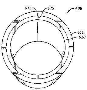
100521 Referring now to Figure 6A, a second test sample 600 of the copper
lined steel
tubing using a copper strip having an original width of 7.34 inches is shown
in
accordance with embodiments of the present disclosure. Test sample 600
includes an
outer steel tubing 610 and an inner copper strip 620 which has been formed
into an inner
liner. During the manufacturing process, copper strip 620 was able to pass
through the
forming process without difficulty, although it did contact the impeder
slightly. Upon
completion of forming, copper strip 620 completely filled the steel tube 610
inner
diameter, and edges 625 of copper strip 620 were forced together at a seam
weld 615 in
steel tube 610.
[0053] Figure 6B shows a micrograph taken of a weld root 616 of seam weld 615
(Figure
6A) from test sample 600. Test sample 600 was polished and etched to reveal
the seam
weld microstructure. As shown, weld root 616 was disturbed by contact from the
copper
12
CA 02640235 2008-09-30
PATENT APPLICATION
ATTORNEY DOCKET NO. 17356/002001
strip causing a weld crack 617 to develop. Weld root 616 may have been
conductively
"quenched," or suddenly cooled, by the copper strip adjacent thereto, thus
causing weld
crack 617 to form.
10054] Referring now to Figure 7A, a third test sample 700 of the copper lined
steel
tubing using a copper strip having an original width of 7.38 inches is shown.
Test sample
700 comprises an outer steel tubing 710 and an inner copper strip 720 which
has been
formed into an inner liner. During the manufacturing process, copper strip 720
was able
to pass through the forming process without difficulty, although it did
contact the
impeder slightly. Upon completion of forming, copper strip 720 completely
filled the
steel tube 710 inner diameter, and edges 725 of copper strip 720 were forced
together at a
seam weld 715 in steel tube 710.
100551 Figure 7B shows a micrograph taken of a weld root 716 of seam weld 715
(Figure
7A) from test sample 700. Test sample 700 was polished and etched to reveal
the seam
weld microstructure. As shown, weld root 716 was disturbed by contact from the
copper
strip causing a weld crack 717 to develop at the outer diameter of the steel
tube.
10056] After running test sample 600 and test sample 700 and observing the
tight fit in
the steel tubing produced by both, it was decided that the planned test using
a 7.76 inch
width copper strip would have resulted in worse results and, therefore, should
not have
been performed. However, it should be understood that this may be relevant
only to the
2-7/8 inch diameter steel tube used.
100571 Referring now to Figure 8A, a fourth test sample 800 of the copper
lined steel
tubing using a copper strip having an initial width of 7.08 inches is shown.
Test sample
800 comprises an outer steel tubing 810 and an inner copper strip 820 which
has been
formed into an inner liner. During the manufacturing process, copper strip 820
was able
to pass through the forming process without incident. Upon completion of
forming, the
copper strip 820 did not completely fill the inner diameter of the steel tube
810. Further,
an edge 825 of copper strip 820 contacted a seam weld root 815.
[0058] Figure 8B shows a micrograph taken of a weld root 816 of seam weld 815
(Figure
8A) from test sample 800 in accordance with embodiments of the present
disclosure.
13
CA 02640235 2008-09-30
PATENT APPLICATION
ATTORNEY DOCKET' NO. 17356/002001
Test sample 800 was polished and etched to reveal the seam weld
microstructure. As
shown, weld root 816 was disturbed by contact from the copper strip causing a
weld
crack 817 to develop at the outer diameter of the steel tube. Edge 825 of
copper strip
820 in contact with weld root 816 may have quenched weld seam 815 and
disrupted the
formation of weld root 816. Further, referring to Figure 8C, seam weld 815
through the
steel material is shown illustrating an "S" pattern which appeared across the
steel tube
wall thickness. The micrograph shows seam weld 815 beginning at an outer
diameter
850 of the steel tube and running through a middle section 855 to an inner
diameter 860
of the steel tube. This pattern may have been caused by edge 825 of copper
strip 820 in
contact with weld root 816, as described above.
100591 Referring now to Figure 9A, a fifth test sample 900 of the copper lined
steel
tubing using a copper strip having an original width of 7.14 inches is shown.
Test sample
900 comprises an outer steel tubing 910 and an inner copper strip 920 which
has been
formed into an inner liner. During the manufacturing process, the copper strip
920 was
able to pass through the forming process without incident. Upon completion of
forming,
the copper strip 920 did not completely fill the inner diameter of the steel
tube 910.
Further, edges 925 of inner copper liner 920 were better centered about a seam
weld root
915 and did not appear to contact it.
[0060] Figure 9B shows a micrograph taken of a weld root 916 of seam weld 915
(Figure
9A) from Test Sample 900 in accordance with embodiments of the present
disclosure.
Test sample 900 was polished and etched to reveal the seam weld
microstructure. As
shown, cracks did not develop in weld root 916 since there was not contact
between the
copper strip and the seam weld in the steel tube. Further, referring to Figure
9C, the seam
weld 915 through the steel material was straight through the steel tube wall
thickness,
rather than having an "S" shape as described previously. This may be due to
the copper
strip not contacting the seam weld.
[00611 Evaluation of the test samples and micrographs showed that the test
samples using
the 7.08 inch and 7.14 inch width copper strips may be the optimum size for
use with the
steel tube in the process disclosed herein. A significant determining factor
in this was
14
CA 02640235 2008-09-30
PATENT APPLICATION
ATTORNEY DOCKET NO. 17356/002001
that the 7.08 inch and 7.14 inch width copper strips, when not in contact with
the seam
weld in the steel tube, did not cause cracks to develop in the seam weld.
[00621 Mechanical properties of test samples 800 and 900 (Figures 8 and 9)
were
compared with reference values from a steel tube milled from the same material
but
without the copper strip. Yield strengths, tensile strengths, and elongation
values were
about the same for the two test samples as compared to the reference tube
material.
Hardness values for test sample 800 were close to hardness values for the
reference tube
material, however the hardness values for test sample 900 were higher than
test sample
800 and reference tube material. Referring to Table 1, mechanical properties
of test
samples 800 and 900 and the reference tube are shown in accordance with
embodiments
of the present disclosure. Mechanical properties shown include annealing
temperatures,
mill speed, yield and tensile strengths, etc.
Table 1- Mechanical Properties
Property Test Sample 800 Test Sample 900 Reference Tube
Full Body Annealing 1080 1080 1120
Temp (C)
Mill Speed (fpm) 60 60 80
OD (min/max in) 2.873/2.877 2.873/2.877 2.883/2.883
Gauge (min/max in) .193/.195 .193095 .191091
Mismatch (mintmax in) .203/.203 .203/.203 .195/.197
Yield Strength (ksi) 74.5 73.3 74.9
Tensile Strength (ksi) 85.2 84.7 87.4
Elongation (%) 26 27 26
Weld Hardness (HRB) 95.5 24.2 HRC 95.0
HAZ Hardness (HRB) 90.4 98.6 92.2
Base Hardness (HRB) 90.8 97.2 91.6
Crush Test Pass Pass Pass
CA 02640235 2008-09-30
PATENT APPLICATION
ATTORNEY DOCKET NO. 17356/002001
Flair Test Pass Pass Pass
100631 Test samples 800 and 900 were subjected to hydrostatic pressure testing
using the
36 inch long test sections. The test samples were tested to failure, with test
sample 800
failing at a pressure of 12,090 psi, and test sample 900 failing at a pressure
of 11,910 psi.
However, neither test sample failed at the seam weld in the steel tubing.
[00641 After inspection of the copper lined steel tube test samples, a copper
strip width
for filling the 2-7/8 x .190 inch steel tube inner diameter in a range between
about 7.38
inches and about 7.08 inches may be desired. Further, the copper strip width
for filling
the steel tube inner diameter may be closer to 7.08 inches. Examination of the
7.08 inch
and 7.14 inch width copper strips showed that if the edges of the copper strip
do not
contact each other or another surface in such a way as to cause a compressive
hoop stress
in the copper strip, the steel tube inner diameter is not completely filled,
and there will be
a gap between the steel tube and inner copper liner. However, when the edges
of the
copper strip did contact each other or another surface, as with the 7.34 inch
and 7.38 inch
width copper strips, the copper completely fills the steel tube inner diameter
without any
gaps.
100651 Inspection of the seam welds in the steel tube may have provided
information
concerning the weld quality of the seam weld when using the copper strips. If
the copper
strip contacts any part of the seam weld during the welding process, the
proper formation
of the weld may be disrupted and an inner diameter weld crack may be formed.
This was
shown in test samples 600, 700, and even 800 when one edge of the copper strip
contacted the seam weld. Because of the contact between the edges of the
copper strip
and the seam weld, the copper strip may be cooling the weld material to
temperatures
below which an acceptable weld may be made. Test sample 900, which was
centered
about the seam weld and did not contact it, did not have cracks develop, and
therefore
may not have degraded the seam weld quality.
100661 Referring back to Table I and a comparison of the mechanical properties
of the
test samples, the mechanical properties may not be affected by the presence of
the copper
16
CA 02640235 2008-09-30
PATENT APPLICATION
ATTORNEY DOCKET NO. 173561002001
strip. A comparison of the hardness values of test sample 800 with the
reference tube
material show that proper hardness values may be achieved. The high hardness
value of
test sample 900 may be due to the seam weld in the steel tube not being
centered under
the seam annealer during the welding of the steel tube. Further, inspection of
the tubing
with an Eddy Current Sector Coil and Encircling Coil, both of which are used
to check
for flaws in the weld, did not appear to be adversely affected by the presence
of the
copper strip. Further, ultrasonic inspection was performed and appeared not to
be
affected by the presence of the copper liner. A mechanical fit of the copper
liner in the
steel tube was also performed in all the test samples. The copper liner did
not fall out of
any of the test samples on its own, however, the copper strip may be pushed
out of the
short test samples by hand with little effort.
[0067] Alternative embodiments to manufacture a copper lined steel tubing
include
centering the copper strip in the steel tube using the fin pass rollers in the
forming stage
(Figure 3 and 4) and adding an internal roller to force the copper against the
steel tube
inner diameter. This addition may prove successful since the copper will be
heated
during the forming and welding processes and may retain the shape without much
elastic
spring back.
[0068] Further, alternative embodiments of manufacturing the copper lined
steel tubing
include milling the steel tube in an oversized configuration initially and
welding. Upon
completion of welding, the steel tube may be resized down to a finished size.
This added
gap while welding may keep the copper strip far enough away from the steel
tube that it
does not quench the weld as much, allowing for stronger welds and alleviating
concerns
about weld cracks.
Empirical Relationships
[0069] Empirical relationships between a given steel tubing size and an
appropriate width
of copper strip for co-forming may be applied over a range of tubing sizes. A
nominal
tubing outer diameter, ODp,be, and a wall thickness, thk,11, are values
dependent on the
overall size of tubing desired. Further, a thickness of the copper strip,
thkc,,, and a seam
17
CA 02640235 2008-09-30
PATENT APPLICATION
ATTORNEY DOCKEr NO. 17356/002001
weld thickness in the steel tubing, thkeld, may be estimated values used in
determining
an appropriate width copper strip. An outer diameter to which the copper strip
may be
formed, OD,,,, is calculated using equation 1 below:
ODca = ODIube - (2 * thk.ii) (Eq. 1)
[0070] The outer diameter of the copper strip may interface with an inner
diameter of the
steel tube. Further, an outer circumference of the copper strip, cirC11j may
be calculated
using equation 2 as follows:
cir. = (Tr * (ODe,be (2 * thk, ,11)))- thkõ,,Id (Eq= 2)
[0071] A steel tube milled outer diameter, OD,riii, may be calculated by
summing a
copper milled oversize tolerance, Cu,,,;II, with the nominal tubing outer
diameter, ODWbe,
as follows in equation 3:
ODill = ODt1,be + Cumru (Eq. 3)
[00721 Still further a steel tube/copper milling outer diameter, ODe,/e,,, may
be calculated
from the following equation 4:
OD.Icu = ODmiil + Cumill (Eq. 4)
[0073] From the above preliminary calculations, a desired welding bead
clearance,
weldel,,,.õeCj between the steel tube and copper line may be calculated from
the following
equation 5:
weldclearance = n. * ((OD.I. - 2 * (thk.,, ))-circa - thkõ,,Id) (Eq S)
2
[0074] Further, an empirical stretch factor for the copper strip may be
calculated for a
range of tube sizes. A ratio, D/t, of the nominal outer diameter of a tube,
ODnibc, and the
wall thickness of the tube, thkwall, is used in relating measured
characteristics of the test
pipe to a range of tube sizes. The ratio is shown in equation 6 as follows:
18
CA 02640235 2008-09-30
PATENT APPLICATION
ATTORNEY DOCKET' NO. 173S61002001
D/t=ODrõe, (Eq.6)
thkõ,,,11
[00751 With the test sample results described previously, and measurements of
the test
samples, the method of selecting an appropriate width copper strip may be
applied over a
range of tube sizes in the following manner. A copper strip stretch factor,
stretch,,, may
be calculated using a ratio of the D/t calculation, D/t*, for 2-7/8 inch steel
tube, and a
ratio of a D/t calculation for a desired tube size to which to apply the
method of
manufacturing lined pipe. The stretch factor may further be formulated in a
manner
known to one having ordinary skill in the art, i.e., the value "X" and the
exponent "e"
used in equation 7. Equation 7 shows a calculation of a copper strip stretch
factor,
stretchc,,.
stretchõ = X * (D / [(t)] ~ (Eq. 7)
100761 A copper strip width, widths,, may be calculated upon running through
the
previous series of preliminary calculations as follows in Equation 8:
width,,, = riru (Eq. 8)
u stretch,
[00771 Embodiments of the present disclosure may provide an improved. method
of
manufacturing lined tubing for several reasons. The method disclosed of
determining
appropriate liner strip widths may allow pipe manufacturers to simultaneously
co-form an
outer base material and inner liner material strips into a tube with an
internal liner while
still using a welded tube milling process. Further, the method allows
manufacturing of a
steel tube with an internal copper liner, for example, whereby the copper
liner is formed
and placed so that the copper liner edges are immediately adjacent to an
internal seam
weld bead in the steel tube.
[00781 Advantageously, a method of determining values of both steel and copper
strip
widths which may allow the copper to completely fill the tubing inner diameter
without
interfering with the seam weld in the steel tubing is presented. Interference
of the copper
19
CA 02640235 2008-09-30
PATENT APPLICATION
ATTORNEY DOCKET NO. 17356/002001
liner with the welding process has been shown to adversely affect the
integrity of the
seam welds, causing weld cracks to form. Furthermore, tube mill set up
parameters that
may allow the copper to completely fill the tubing inner diameter without
interfering with
the seam weld in the steel tubing, specifically, running less reduction in fin
roller passes
and larger reduction in sizing passes are presented.
[0079] Still further, advantages are provided from embodiments of the present
disclosure
in selecting various combinations of steel and copper diameters and wall
thicknesses that
may satisfy manufacturing requirements and design requirements of customers.
More
particularly, requirements such as sufficient copper cross-sectional area and
internal
clearance for features including, but not limited to ceramic centralizers may
be satisfied.
[0080] Embodiments of the present disclosure may advantageously identify
performance
criteria that measure the suitability of the copper lined steel tubing to
perform properly.
These criteria include, but are not limited to, tube ovality, pressure
integrity, internal
ovality/clearance, seam weld integrity, and the strength of the interference
fit between the
steel tube and the copper liner.
[0081] Embodiments of the present disclosure may provide an accurate and
reliable
method of calculating material requirements for lined steel tubing. For
example, the
method may allow a copper strip width to be calculated for use in forming
lined steel
tubing. Optimum mill parameters may be identified from corresponding
performance
criteria, improving mill setup and increasing production. The accuracy of the
method
may further allow manufacturers of lined welded pipe to calculate appropriate
strip
widths before manufacturing. The ability to accurately calculate material
needs may
increase productivity of lined tubing, and decrease material waste from errors
in
estimating the amount of material needed. Further, estimated costs to
manufacture in
commercial production quantities may be more accurately determined, which in
turn may
result in higher productivity and lower material costs.
[0082] While the invention has been described with respect to a limited number
of
embodiments, those skilled in the art, having benefit of this disclosure, will
appreciate
that other embodiments may be devised which do not depart from the scope of
the
CA 02640235 2008-09-30
PATENT APPLICATION
ATTORNEY DOCKET NO. 17356/002001
invention as disclosed herein. Accordingly, the scope of the invention should
be limited
only by the attached claims.
21