Note : Les descriptions sont présentées dans la langue officielle dans laquelle elles ont été soumises.
CA 02640457 2008-07-25
WO 2007/089566 PCT/US2007/002141
PREFORM AND CONTAINER HAVING THREAD GROOVE
CROSS-REFERENCE TO RELATED APPLICATIONS
[0001] This application claims the benefit of U.S. Provisional
Application No. 60/763,203 filed on January 27, 2006. The disclosure of which
is
incorporated herein by reference.
TECHNICAL FIELD
[0002] This disclosure generally relates, to plastic containers for
retainin.g a commodity, and in particular a liquid commodity. More
specifically,
this disclosure relates to a plastic preform and resultant container having a
groove formed in the molded surface where threads of a given closure will ride
during capping.
BACKGROUND
[0003] As a result of environmental and other concerns, plastic
containers, more specifically polyester and even more specifically
polyethylene
terephthalate (PET) containers are now being used more than ever to package
numerous commodities previously supplied in glass containers. Manufacturers
and fillers, as well as consumers, have recognized that PET containers are
lightweight, inexpensive, recyclable and manufacturable in large quantities.
. [0004] * ' Blow-molded plastic containers have become commonplace in
packaging numerous commodities. PET is a crystallizable polymer, meaning
that it is available in an amorphous form or a semi-crystalline form. The
ability of
a PET container to maintain its material integrity relates to the percentage
of the
PET container in crystalline form, also known as the "crystallinity" of the
PET
container. The following equation defines the percentage of crystallinity as a
volume fraction:
% Crystallinity = ( )x100
P~-Aa
1
CA 02640457 2008-07-25
WO 2007/089566 PCT/US2007/002141
where p is the density of the PET material; pa is the density of pure
amorphous
PET material (1.333 g/cc); and pc is the density of pure crystalline material
(1.455 g/cc).
[0005] Container manufacturers use mechanical processing and
thermal processing to increase the PET polymer crystallinity of a container.
Mechanical processing involves orienting the amorphous material to achieve
strain hardening. This processing commonly involves stretching an injection
molded PET preform along a longitudinal axis and expanding the PET preform
along a transverse or radial axis to form a PET container. The combination
promotes what manufacturers define as biaxial orientation of the molecular
structure in the container. Manufacturers of PET containers currently use
mechanical processing to produce PET containers having approximately 20%
crystallinity in the container's sidewall.
[0006] Thermal processing involves heating the material (either 15 amorphous
or semi-crystalline) to promote crystal growth. On amorphous
material, thermal processing of PET material results in a spherulitic
morphology
that interferes with the transmission of light. In other words, the resulting
crystalline material is opaque, and thus, generally undesirable. Used after
mechanical processing, however, thermal processing results in higher
crystallinity and excellent clarity for those portions of the container having
biaxial
molecular orientation. The thermal processing of an oriented PET container,
which is known as heat setting, typically includes blow molding a PET preform
against 'a mold heated to a temperature of approximately 250 F - 350 F
(approximately 121 C - 177 C), *and holding the blown container against the
heated mold for approximately two (2) to five (5) seconds. Manufacturers of
PET
juice bottles, which must be hot-filled at approximately 185 F (85 C),
currently
use heat setting to produce PET bottles having an overall crystallinity in the
range of approximately 25% -35%.
[0007] Typically, an upper portion of the plastic container defines an
opening. This upper portion is commonly referred to as a finish and includes
some means for engaging a cap or closure to close off the opening. In the
traditional injection-stretch blow molding process, the finish remains
substantially
2
CA 02640457 2008-07-25
WO 2007/089566 PCT/US2007/002141
in its injection molded state while the container body is formed below the
finish.
The finish may include at least one thread extending radially outwardly around
an annular sidewall defining a thread profile. In one application, a closure
member or cap may define a complementary thread, or threads, that are
adapted to cooperatively mate with the threads of the finish. Generally,
clockwise rotation of the cap encourages an upper surface of the cap threads
to
be retained by lower surfaces of the threads on the finish. In some
applications,
however, external thread profiles formed on the finish may require a non-
desirable large amount of material to manufacture.
SUMMARY
[0008] Accordingly, the present disclosure provides a finish for a
plastic container including an upper portion having a mouth defining an
opening
into the container. At least one groove is defined around a radial sidewall of
the
upper portion. The groove slopes gradually downward along the radial sidewall
and away from the opening.
[0009] A preform adapted to be molded into a plastic container
includes an upper portion having a mouth defining an opening into the
container.
The preform includes at least one groove defined around a radial sidewall of
the
upper portion. The groove slopes gradually downward along the radial sidewall
to a terminal end.
[0010] A closure member is adapted to selectively mate with a finish
on a container. The closure member includes a lower portion defining an
opening and an upper portion defining a cover. At least one thread is formed
on
an inner surface of a radial sidewall extending between the lower portion and
the
upper portion.
[0011] Additional benefits and advantages of the present disclosure
will become apparent to those skilled in the art to which the present
disclosure
relates from the subsequent description and the appended claims, taken in
conjunction with the accompanying drawings.
3
CA 02640457 2008-07-25
WO 2007/089566 PCT/US2007/002141
BRIEF DESCRIPTION OF THE DRAWINGS
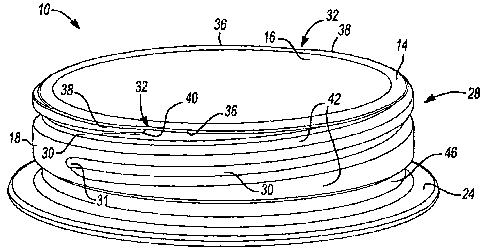
[0012] FIG. 1 is a perspective view of a finish of a plastic container
constructed in accordance with the teachings of the present disclosure;
[0013] FIG. 2 is a top plan view of the finish of FIG. 1;
[0014] FIG. 3 is a side view of the finish of FIG. 1;
[0015] FIG. 4 is a sectional view of the finish taken along line 4- 4 of
FIG. 3;
[0016] FIG. 5 is a perspective view of a preform used for construction
of an exemplary plastic container having the finish of FIG. 1;
[0017] FIG. 6 is a side view of the preform of FIG. 5 shown with an
exemplary molded container in phantom;
[0018] FIG. 7 is a sectional view of the preform taken along line 7- 7
of FIG. 6;
[0019] FIG. 8 is a top plan view of the preform of FIG. 5; and
[0020] FIG. 9 is a sectional view of a closure member or cap having a
tamper-evidence band and constructed in accordance with the teachings of the
present disclosure, the cap shown assembled onto the container finish shown in
FIG. 1.
DETAILED DESCRIPTION
[0021] The following description is merely exemplary in nature, and is
in no way intended to limit the disclosure or its application or uses.
[0022] This disclosure provides for a container finish having a
significantly reduced weight, while enhancing the interface between a closure
member or cap and the container, and meeting filling line temperature and
speed
demands. Significant weight reductions are achieved through the elimination of
material from the container wall of a standard thread profile as well as the
elimination of material in other areas of the finish, which represent areas
where
plastic can be removed without negatively affecting the sealability function
of the
closure member or cap and the container.
[0023] Additionally, a by-product of the disclosed container finish is an
improvement to closure function. In this regard, the disclosed finish may be
less
4
CA 02640457 2008-07-25
WO 2007/089566 PCT/US2007/002141
damaging to frangible connectors incorporated in tamper-evidence closures,
reducing the potential for premature closure/tamper-evidence band separation
during application. The smoother, more cylindrical finish disclosed provides
an
opportunity to keep an applied closure member or cap more concentric with the
finish, reducing the potential for uneven loading on the frangible connectors
which secure the tamper-evidence band to the body of the closure member or
cap. Such stability improves tamper-evidence band separation.
[0024] Traditionally, the distance between the top seal surface of a
container and the start of the container's threads varies slightly during
normal
production. As this distance varies, it affects the rotational position of an
applied
closure, and thus the relative location of the tamper-evidence band retention
features to the mating features on the finish. The disclosed container finish
eliminates the above-mentioned distance and variability, and thereby
contributes
to improved tamper-evidence band closure performance.
[0025] With initial reference to FIGS. 1 - 4, a finish of a plastic, e.g.
polyethylene terephthalate (PET), hot-fillable container is shown and
generally
identified at reference numeral 10. A closure member or cap 12 (FIG. 9,
described in detail later) may be used to selectively mate with the finish 10
in a
closed or assembled position. The finish 10 of the present teachings includes
a
top 14 defining a mouth or opening 16, an annular sidewall 18 and a support
ring
24. The opening 16 allows the plastic container to receive a commodity. The
annular sidewall 18 generally defines a groove region 28. The groove region 28
provides a means for attachment of the closure member or cap 12. The groove
region 28 is formed by a pair of grooves 30 generally defining a helical
pattern.
Each groove 30 initiates at a groove entrance 32 and sweeps gradually
downward about 180 degrees to about 220 degrees around the annular sidewall
18 of the finish 10 to a terminal end 31. Accordingly, the terminal end 31
prevents over torquing of the closure member or cap 12, which could
compromise the seal integrity of the closure member or cap 12 of the
container.
The terminal end 31 also aids in orienting the closure member or cap 12 in
relation to the container.
5
CA 02640457 2008-07-25
WO 2007/089566 PCT/US2007/002141
[0026] The groove entrance 32 is generally defined at an intersection
between an inward sweeping radial lip 36 and an outward sweeping radial lip
38.
As best illustrated in FIG. 2, the inward sweeping radial lip 36 defines an
arcuate
path having a decreasing radius in the clockwise direction. The outward
sweeping radial lip 38 defines an arcuate path having an increasing radius in
the
clockwise direction. A ramp 40 (FIG. 1) is defined at the groove entrance 32
and
leads into the respective grooves 30. In another example, the top 14 may
define
a constant outer radius without incorporating the inward and outward sweeping
radial lips 36 and 38, respectively. It is appreciated that a single groove,
or two
or more grooves may be provided on the anriufar sidewall 18. Lands 42 define
surfaces formed between the grooves 30 on the annular sidewall 18. A radial
channel 46 is formed between the annular sidewall 18 and the support ring 24.
As will be described in greater detail later, the radial channel 46 may serve
as a
means for capturing a break-away, tamper-evidence (TE) band 47 attached to
the closure member or cap 12. It is appreciated that the radial channel 46 may
also include notches, ratchets or similar geometry for dislodging the break-
away,
TE band 47 of the closure member or cap 12 during the opening of the
container. In another example, the grooves 30 can extend all the way into the
radial channel 46 effectively eliminating any terminal end of the grooves 30
(i.e.
terminal end 31 discussed above).
[0027] The pair of grooves 30 of the finish 10 each define a debossed
(grooved) threaded profile around the annular sidewall 18. When compared to
traditional injection molded finishes having an embossed (raised) threaded
profile, the finish 10 of the present disclosure may represent a material
savings
of about 15% to about 20% of the overall container weight and more
specifically
about 50%, in weight, of traditional injection molded finishes. The present
disclosure is particularly useful in hot-fill applications where thicker,
heavier
finishes have been required to withstand the heat generated from hot-fill
processes thereby allowing for traditional opening diameters and finish wall
thicknesses to be maintained while significantly light weighting the
container.
Thus, the disclosed finish 10 is capable of withstanding the rigors associated
6
CA 02640457 2008-07-25
WO 2007/089566 PCT/US2007/002141
with hot-fill processes, resulting in the same or less distortion as is found
in
traditional container designs having thicker, heavier finishes.
[0028] In another advantage over traditional threaded finish containers,
a finish 10 having grooves 30 is more comfortable for a user's mouth to engage
and therefore drink from. In this way, a user's mouth can rest more
comfortably
on a finish free of projecting threads. Furthermore, it is easier for a user
to form
a seal between their mouth and the finish 10 having grooves 30 as compared to
a finish having projecting threads.
[0029] A plastic container may be designed to retain a commodity
during a thermal process, typically a hot-fill process. For hot-fill bottling
applications, bottlers generally fill the container with a liquid or product
at an
elevated temperature between approximately 155 F to 205 F (approximately
68 C to 96 C) and seal the container at the finish 10 with the closure member
or
cap 12 before cooling. In addition, the plastic container may be suitable for
other
high-temperature pasteurization or retort filling processes or other thermal
processes as well.
[0030] Turning now to FIGS. 3 and 4, exemplary dimensions for the
finish 10 will be described. It is appreciated that other dimensions may be
used.
A diameter Dl of the finish 10 taken at the lands 42 of the annular sidewall
18
may be 39.24 mm (1.55 inches). A diameter D2 of the finish 10 taken at the
grooves 30 of the annular sidewall 18 may be 36.86 mm (1.45 inches).
Accordingly, the diameter D2 may be at least 1 mm (0.04 inch) less than the
diameter Dl. A diameter D3 of the finish 10 taken at the radial channel 46 may
be 37.47 mm (1.48 inches). Similarly, the diameter D3 may be at least 1 mm
(0.04 inch) less than the diameter Dl. As such, the diameter D2 and the
diameter D3 may be less than the diameter Dl. A diameter D4 of the finish 10
taken at the support ring 24 may be 44.48 mm (1.75 inches). As a result of the
reduction in the cap diameter, the diameter D4 is similarly reduced. A height
Hi
taken from the top 14 to the beginning of the radial channel 46 may be 8.51 mm
(0.34 inch). A height H2 of the support ring 24 may be 1.15 mm (0.05 inch). A
height H3 of the radial channel 46 may be 3.18 mm (0.13 inch). A height H4
taken from the top 14 to the first groove 30 at the completion of the ramp 40
may
7
CA 02640457 2008-07-25
WO 2007/089566 PCT/US2007/002141
be 1 mm (0.04 inch). A height H5, or a height of the groove 30, may be 2.39 mm
(0.09 inch). A height H6, or a height of the land 42, may be 1.52 mm (0.06
inch).
A seal width W may be 0.82 mm (0.03 inch). In this regard, the seat width W
may not be greater than about 50% to about 60% of a wall thickness T2 taken
from land 42 to the inner diameter of the opening 16.
(0031] With continued reference to FIG. 4, various radii will now be
listed with exemplary dimensions. R1, R2, R4 and R5 may be 0.25 mm (0.01
inch). R3 may be 0.76 mm (0.03 inch). R6, R8 and R9 may be 0.51 mm (0.02
inch). R7 may be 1.02 mm (0.04 inch). As such, a minimum dimension for R1,
R2, R4, R5, R6, R7 and R9 may be 0.1 mm (0.004 inch). Again, it is appreciated
that other dimensions may be used. However, the above-described dimensions
provide the closure member or cap 12 with good spin capabilities when engaging
the grooves 30.
[0032] Turning now to FIGS. 5 - 8, a preform 50 used to mold an
exemplary container having the finish 10 will be described. The plastic
container
of the present teachings is a blow molded, biaxially oriented container with a
unitary construction from a single or multi-layer material. A well-known
stretch-
molding, heat-setting process for making hot-fillable plastic containers
generally
involves the manufacture of the preform 50 through injection molding of a
polyester material, such as polyethylene terephthalate (PET), having a shape
well known to those skilled in the art similar to a test-tube with a generally
cylindrical cross section and a length typically approximately fifty percent
(50%)
that of the resultant container height. A machine (not illustrated) places the
preform 50 heated to a temperature between approximately 190 F to 250 F
(approximately 88 C to 121 C) into a mold cavity (not illustrated) having a
shape
similar to the resultant plastic container.
[0033] The rnold cavity (not illustrated) may be heated to a
temperature between approximately 250 F to 350 F (approximately 121 C to
177 C). A stretch rod apparatus (not illustrated) stretches or extends the
heated
preform 50 within the mold cavity to a length approximately that of the
resultant
container thereby molecularly orienting the polyester material in an axial
direction generally corresponding with a central longitudinal axis of the
resultant
8
CA 02640457 2008-07-25
WO 2007/089566 PCT/US2007/002141
container. While the stretch rod extends the preform 50, air having a pressure
between 300 PSI to 600 PSI (2.07 MPa to 4.14 MPa) assists in extending the
preform 50 in the axial direction and in expanding the preform 50 in a
circumferential or hoop direction thereby substantially conforming the
polyester
material to the shape of the mold cavity and further molecularly orienting the
polyester material in a direction generally perpendicular to the axial
direction,
thus establishing the biaxial molecular orientation of the polyester material
in
most of the container. Typically, material within the finish 10 and a sub-
portion
of the base are not substantially molecularly oriented. The pressurized air
holds
the mostly biaxial molecularly oriented polyester material against the mold
cavity
for a period of approximately two (2) to five (5) seconds before removal of
the
container from the mold cavity.
[0034] Alternatively, other manufacturing methods using other
conventional materials including, for example, polypropylene, high density
polyethylene, polyethylene naphthalate (PEN), a PET/PEN blend or copolymer,
and various multilayer structures may be suitable for the manufacture of
plastic
containers. Those having ordinary skill in the art will readily know and
understand plastic container manufacturing method alternatives.
[0035] The preform 50 may be defined in terms of complementary
features of a finished container. For exemplary purposes, a formed container
56
is shown in phantom in FIG. 6. As such, the container 56 may include a
shoulder region 60. The shoulder region 60 merges into and provides a
transition between the finish 10 and a sidewall portion 62. The sidewall
portion
62 extends downward from the shoulder region 60 to a base 64. The base 64
functions to close off the bottom portion of the plastic container 56 and,
together
with the finish 10, the shoulder region 60, and the sidewall portion 62, to
retain
the commodity. The specific construction of the shoulder region 60, the
sidewall
portion 62 and the base 64 are merely exemplary and may vary according to
particular applications. The support ring 24 may be used to carry or orient
the
preform 50 through and at various stages of manufacture. For example, the
preform 50 may be carried by the support ring 24, the support ring 24 may be
9
CA 02640457 2008-07-25
WO 2007/089566 PCT/US2007/002141
used to aid in positioning the preform 50 in the mold, or an end consumer may
use the support ring 24 to carry the plastic container 56 once manufactured.
[0036] With specific reference now to FIGS. 7 and 8, exemplary
dimensions for the preform 50 will be described. It is appreciated that the
finish
10 of the preform 50 is equivalent to the finish 10 as described in FIGS. 1-
4.
As such, similar reference numerals will be used to designate like components.
An inner diameter D5 of the opening 16 may be 34.08 mm (1.34 inches). A
height H6 taken from the top 14 of the finish 10 to the bottom of the support
ring
24 may be 13.49 mm (0.53 inch). A height H7 taken from the top 14 of the
finish
10 to an onset 66 of the preform 50 shoulder region may be 14.30 mm (0.56
inch). A wall thickness T1 taken at the preform 50 shoulder region may be 3.62
mm (0.14 inch). The wall thickness T2 taken from land 42 to the inner diameter
of the opening 16 may be 2.09 mm (0.08 inch). An angle Al taken from a
longitudinal centerline 67 to an inner wall surface 68 may be 27 degrees. An
angle A2 taken from the longitudinal centerline 67 to an outer wall surface 69
may be 20 degrees.
[0037] With reference to FIG. 9, the closure member or cap 12 is
shown engaged to the finish 10 in a closed or assembled position. In the
assembled position, the closure member or cap 12 engages the finish 10 to
preferably provide a hermetical seal to the plastic container 56. The closure
member or cap 12 is preferably of a plastic or metal material suitable for
subsequent thermal processing, including high temperature pasteurization and
retort. According to the present teachings, the closure member or cap 12 may
define raised, outwardly extending threads 70 for rotatably engaging the
grooves
30 of the finish 10. In the exemplary finish 10, a two lead configuration is
shown.
As such, a pair of threads 70 defined on the closure member or cap 12 is
adapted to be received by the complementary pair of grooves 30. While two
threads 70 are shown in the sectional view of FIG. 9, it is appreciated that
one or
more than two threads may be provided. To initiate gripping of the threads 70
within the respective grooves 30, the closure member or cap'12 may be placed
on the top 14 and rotated until both leads of threads 70 are accepted at the
groove entrance 32. The ramp 40 (FIG. 1) progressively directs the respective
CA 02640457 2008-07-25
WO 2007/089566 PCT/US2007/002141
threads 70 within the grooves 30 as the closure member or cap 12 is rotated in
a
clockwise direction. As explained above, each of the grooves 30 are defined
around approximately 180 degrees to approximately 220 degrees of the annular
sidewall 18. To rotate the closure member or cap 12 into a sealed position
with
the finish 10, the closure member or cap 12 may not need to rotate the entire
180 to 220 degrees. In one example, the threads 70 of the closure member or
cap 12 may rotate approximately 160 degrees to approximately 200 degrees
around the grooves 30 to attain a sealed position. In other words, each of the
embossed (raised) threads 70 of the closure member or cap 12 may be lesser in
length than each of the respective grooves 30 of the finish 10. Additionally,
the
threads 70 of the closure member or cap 12 may be longer than or the same in
length as each of the respective grooves 30 of the finish 10 in order to
orient the
closure member or cap 12 in relation to the container 56. The finish 10,
having
debossed (inward) grooves 30 of the current disclosure, enables use of a
closure
member or cap 12 being shorter in height and smaller in diameter than caps
currently used with traditional finishes of the same diameter having embossed
(raised) threads. In one example, an outer diameter of the closure member or
cap 12 can be reduced to about 41 mm (1.61 inches) as compared to a 43 mm
(1.69 inches) outer diameter required for an equivalent conventional cap
having
grooves. Furthermore, as illustrated in FIG. 9, the outer diameter of the
closure
member or cap 12 can be substantially equivalent to an outer diameter defined
at the support ring 24. This represents a significant weight savings, as less
material is required for the closure member or cap 12. Accordingly, the finish
10
provides the container 56 with the ability to retain the closure member or cap
12,
and withstand the associated application torque while also providing easy
removal of the closure member or cap 12.
[0038] The closure member or cap 12 is shown with the TE band 47.
The closure member or cap 12 can generally include a cover 80 at an upper end.
The TE band 47 is further defined by a band body 82 and a flap 84 extending
therefrom. The flap 84 extends generally inboard of the band body 82. The TE
band 47 of the closure member or cap 12 is designed to 'ride over the annular
sidewall 18 of the finish 10 in a forward (downward) direction when the
closure
11
CA 02640457 2008-07-25
WO 2007/089566 PCT/US2007/002141
member or cap 12 is initially applied to the container 56. When the closure
member or cap 12 is initially unscrewed (moved upward), the flap 84 engages
the annular sidewall 18 and therefore breaks away the TE band 47 from the
closure member or cap 12. The prevention of the TE band 47 moving back up
on the finish 10 when the closure member or cap 12 is removed thus creates the
necessary engagement interface and force that effectively removes the TE band
47 from the closure member or cap 12, leaving it on the container finish 10.
[0039] While ttie above description constitutes the present disclosure,
it will be appreciated that the disclosure is susceptible to modification,
variation
arfd change without departing from the proper scope and fair meaning of the
accompanying claims.
12