Note : Les descriptions sont présentées dans la langue officielle dans laquelle elles ont été soumises.
CA 02640787 2013-08-09
ARRAY FLUORESCENCE EQUALIZATION METHOD
FIELD OF THE INVENTION
The invention relates to a method of assay spot and array fluorescence
intensity
equalization by inducing uniform removal of fluid vapor during controlled
drying of
assay spot array components.
DESCRIPTION OF THE RELATED ART
An advantage of fluorescence spectroscopy is measurement and analysis of
various
features that are related to fluorescence quantum yield and /or lifetime of a
fluorescence
emitting body. The emitted fluorescence intensity is a function of emitter
concentration,
extinction co-efficient (absorbing power) at the excitation wavelength and
quantum yield
at the emission wavelength. However, time-resolved and steady-state
fluorescence
quenching is responsible for significant variation in fluorescence intensity
measurement.
Variations and heterogeneity in intensity fluctuates proportionately with
fluorescence
quencher concentrations, caused in part by transient effects in diffusion and
the nature of
the fluorophore-quencher interaction. Analysis of time-resolved frequency-
domain and
steady-state data has shown that quenching rates depend exponentially on the
fluorophore-quencher distance from the emitter, reflecting electron transfer
and exchange
interactions as the probable quenching mechanisms.
Technologies for improving quantitative fluorescence signal detection emitted
from assay
spots and micro-arrays have been incorporated into methods for improving
detection by
improving detection hardware and modification of fluorescence signal
processing;
illustrated for example in U.S. Patent 6,690,461, 2004, by Tamura et al.,
entitled
"Methods for displaying micro-array information" which uses computer image
data
CA 02640787 2013-08-09
processing of accumulated intensities; U.S. Patent Application 200420138,
2004, by
Caren et al,. entitled "Polynucleotide array fabrication" which examines dried
spots to
illustrate resulting manufacturing errors caused by drying; U.S. Patent
Application
2006/0063197 Al, by Anderson et al., entitled "Quality control and
normalization
methods for protein micro-arrays" which compares chemiluminescent reponses by
comparing buffer and printed spots for volume/concentration dye based
correction; U.S.
Patent Application 2006127946, by Montagu and Webb, entitled "Reading of
fluorescent
arrays" which compares intensity calibration features in the array itself and
WO Patent
Application 2006058031, by Mohammed and Dzidic, entitled "Microarray quality
control" where printed spots are imaged by measuring fluorescence across
spotted sample
in two dimensions and then compared to printed reference images.
State of the art for deriving quantitative fluorescence measurement has
emphasized on
optimizing accurate detection of the signal and correction of the signal
preceding signal
analysis, based on the assumption that this signal correctly reflects the
emitter's
concentration. This approach is illustrated by European application EP1774292,
(2007)
by Ge et al, entitled "A calibration slide for fluorescence detection
instruments and
process of preparation", which invention relates to routine calibration slides
for
fluorescence detection instruments, including the calibration of micro-array
scanners,
fluorescent microscopy, fluorescence spectrometry and fluorescence multi-well
plate
reading.
Current technologies for improving the coefficient of variance (%c.v.) in
fluorescence
intensity quantitation observed between spots and micro-arrays have been
primarily
focused on improving signal intensity readings obtained by modification of
fluorescence
signal and image processing. A method is needed for improving and setting
quantitative
uniformity comparison of fluorescence signal intensity between spots having
identical
content, when printed from a common source fluid, and to provide uniform
signal levels
at similar content concentrations.
2
CA 02640787 2013-08-09
There is a need for a method for inducing a uniform state of hydration by
controlled
drying of micro-arrays and spots to minimize fluorescence signal quenching
effects of
fluids and spatial distribution of spot contents e.g. particles, followed by
controlled and
contained removal of signal quenching fluid vapors from within and in the
vicinity of the
moist array and spots to enable comparative quantitative signal analysis. It
is desirable to
provide such method of fluid removal followed by vapor removal using a novel,
simple
to implement method.
There is a further need to provide for assay spot signal equalization that
reduces
quenching components to a relative concentration enabling enhanced comparative
analysis of bio-array data using short drying time.
There is a need for such a method that randomizes any non-uniformity in the
source
fluorescence volume, resulting in quantitation of a more uniform illumination
signal for
assay spots.
There is a further need for such a method where respective divergent and
diffusing
quenching sources are minimized, providing comparable fluorescence signal
intensities
proximate to each assay spot, as measured and confirmed using a recognized
reference
standard to calculate a coefficient of variance (cv).
SUMMARY OF THE INVENTION
The present invention is a method for fluorescence intensity equalization;
preferably by
reducing quenching components to a relative concentration enabling enhanced
comparative analysis of assay data. The method involves drying an assay device
to
remove vapor in the proximity of at least one immobilized array of molecular
probes that
bind to an analyte bound to a fluorescent marker.
3
CA 02640787 2013-08-09
According to an aspect of the present invention, there is provided a method
for
fluorescence intensity equalization comprising the following steps: providing
an assay
device having at least one immobilized array of molecular probes that bind to
an analyte
bound to a fluorescent marker; providing drying apparatus comprising an
aspiration tube
having open first and second ends, the second end of the aspiration tube being
connected
a vacuum source for applying a vacuum through said tube; placing the first end
of the
aspiration tube in proximity of said at least one immobilized array of
molecular probes;
and applying a vacuum through said aspiration tube for removing vapor from
said at least
one immobilized array of molecular probes.
BRIEF DESCRIPTION OF THE DRAWINGS
The present invention together with the above and other objectives and
advantages may
best be understood from the following detailed description of preferred
embodiments of
the invention illustrated in the figures, wherein:
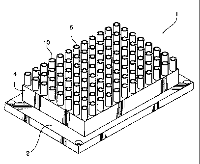
Figure 1 is a perspective view of a preferred embodiment of a drying apparatus
of the
present invention;
Figure 2 is a top elevation view of an assay device used in association with
the present
invention;
Figure 3 is a plot of drying time versus relative humidity where drying is
carried out at
different temperatures; and
Figure 4 is a bar graph illustrating a co-efficient of variation (% cv) for
spot for
immunoglobulin spots of IgA, IgG, and IgM at 4 minutes when continuous vacuum
induced air flow is modulated to shear over the elevation of a spot at a
distance of 3.0
mm and a distance of 4 mm.
4
CA 02640787 2013-08-09
DETAILED DESCRIPTION OF THE PREFERRED EMBODIMENTS
As shown in Figure 1, drying apparatus 1 has a frame 2. The frame 2 is can be
coupled
to an actuator (not shown) that moves the frame in thee dimensions along an
XYZ plane.
The actuator functions as a displacement means and can be one of many
actuators known
in the art. A preferred actuator is ELx405 Microplate Washer, BioTek
Instruments,
U.S.A.
The drying apparatus includes a housing 4 that is attached to the frame 2. A
plurality of
aspiration tubes 10 is located in the housing. In alternate embodiments, the
dryer can
have as few as one tube. Each of the tubes 10 defines a length, and defines a
longitudinal
bore 12 along the length between a first open end 6 and a second open end 8.
As shown
in Figure 3, the longitudinal bore 12 is preferably tapered wherein the first
open end 6 is
has a greater diameter than the diameter of the second open end 8.
The length of the aspiration tube 10 may vary. In the preferred embodiment,
the length is
sufficient to maintain an aspect ratio of about 18 derived in concert with
opening
diameters aspect ratio of about 1.7 based on cone angle pitch at 3.5 degrees.
The wall
thickness of the aspiration tube 10 at the first open end 6 in proximity of a
substrate is
preferably about 400 p.m. The diameter of the first open end 6 is about 5 mm.
The second
open end 6 has a diameter of about 2 mm, a preferred diameter to allow
constant airflow
through all aspiration tubes 10 into a vacuum head being modulated by setting
of the flow
access across the substrate surface area as defined by the perimeter and wall
height ratio
of an assay device containing a removable fluid load.
The drying apparatus 1 includes means for applying a vacuum to the second open
end 8
of each aspiration tube. The means for applying a vacuum can be any of various
such
means known in the art. In the preferred embodiment, the vacuum means is
Vacuum
pump, ME 4C NT Vario, VacuuBrand, U.S.A.
The dryer apparatus 1 of the preferred embodiment is preferably used to dry an
assay
device and in particular of the type such as assay device 50 shown in Figure
4. The assay
CA 02640787 2013-08-09
device 50 has a plurality of wells 52. Each of said wells 50 are separated by
intersecting
walls 54; providing effectively a superstructure onto the plate, thereby
forming a single
well or separate multiple wells. Multiple wells have the added benefit of
allowing
multiple objects to be processed on the same plate as each well can have an
assay printed
thereon in form of protein spots in micro-array format, for example.
Analysis of data from bio-arrays printed on an assay device is based on the
detection of
fluorescence signals from labeled target molecules that specifically interact
with an
immobilized array of molecular probes. In the preferred embodiment, the array
of
molecular probes is immobilized capture antibodies printed in protein spots on
the assay
device. The capture antibodies bind to an antigen that is bound to a
fluorescent marker.
The molecular probes may be attached directly onto a substrate. In the
preferred
embodiment, a three-dimensional bio-array (the arrayed probes) are attached to
a glass
substrate by an epoxy coated substrate carrier.
In a typical protein spot assay, a fluid sample is mixed with a reagent, such
as a
fluorescent labelled antibody, specific to a particular analyte (the substance
being tested
for), such as an antigen. Another type of antibody is immobilized on a solid
support in a
protein spot. The fluorescent labelled antibody is mixed with the sample. A
complex
between the fluorescent labelled antibody, the substance being tested for and
the second
antibody is formed, immobilizing the marker in the protein spot. The
fluorescent marker
is then detected. The amount of antigen present is proportional to the
intensity of
fluorescence emitted from the protein spot. The preferred embodiment of the
present
invention is carried out on an assay device that has a plurality or array of
different protein
spots.
The present invention provides a method of equalizing the level of
fluorescence signal
emanating from assay spots wherein the capture of an analyte, labeled with a
fluorescent
marker, in the spots indicates the presence of the analyte. Factors that
quench the level of
fluorescence to be measured or otherwise distort the fluorescent signal to be
measured,
adversely affects the results of the assay.
6
CA 02640787 2013-08-09
In operation, the present invention provides a method for removal of vapors,
especially
from micro-array protein spot assay devices. In the preferred embodiment, the
method is
implemented by the dryer apparatus 1, and involves removing fluid vapors from
the
surface of an assay device typically used in washing and processing protein
spot micro-
arrays to effectively induce uniform states of hydration in the three
dimensional protein
spots that constitute a micro-array. Without being bound by theory, we have
found that
the micro-array constituent state of hydration directly affects the signal
intensity thereby
enabling enhanced quantitative analysis of bio-array data, especially when
applied to
diagnostic grade micro-array signals. The method of the present invention
provides
drying of protein spot bio-array formats without inducing negative and
disruptive effects,
ensuring that there is a reduction in the fluorescent signal quenching
components to a
relative concentration that enables enhanced comparative analysis of assay
data.
Vapor removal is activated and accomplished by modulating air flow over the
vapor
logged, differentially hydrated substrate platform and partially dry object.
Effectively,
dryer apparatus 1 modulated air flow currents under controlled conditions are
actively
moved across vapor sources to remove vapors, resulting in a consistent state
of
dehydration of objects located within the vacuum induced air flow currents.
The induced
air flow currents simultaneously contain, isolate and disinfect the possibly
contaminated
and/or infectious materials carried within the consequent moist exhaust air
flow.
Vapor removal is applied by drying apparatus 1 in order to equilibrate any
fluid vapor
present about and within a well 52. The preferred vacuum applied to air flow
modulation
ranges between about 106 decaPascals to about 10132 decaPascals. The X-Y co-
ordinate
matrix spacing of the tubes 10, in the preferred embodiment, coincides with
the X-Y co-
ordinate matrix placement of the well superstructure attached to the assay
device 50. As
both X-Y matrices provide accurate alignment, each well 52 will have a single
aspiration
tube 10 inserted at the centre of each well 52, with the aspiration tube 10
first opening 6
placed at a predetermined, optimal distance above the surface of the plate
substrate which
preferably ranges from about 20 micrometers to 5 millimeters. The preferred
setting
provides optimal air flow when the height of the intake end of the aspiration
tube is set
7
CA 02640787 2013-08-09
about 4 mm above a protein spot micro-array. Vacuum aspiration removes any
residual
fluid vapor.
The method of the present invention randomizes any non-uniformity in a source
fluorescence volume, resulting in quantitation of a more uniform illumination
signal for
assay spots. Divergent and diffusing quenching sources are minimized,
providing
comparable fluorescence signal intensities proximate to each assay spot, as
measured and
confirmed using a recognized reference standard to calculate a coefficient of
variance
(cv).
The preferred embodiment of the present invention is a method for comparative
quantitative analysis of bio-array protein spot fluorescence signal to
generate intra and
inter-spot uniform drying of spots by simultaneous, equivalent reduction of
washing and
processing fluid vapors as well as residual moisture adhering in the vicinity
of the array
to be analyzed. Any non-uniformity in the hydration of fluorescent arrays
translates into
variations in the intensity of the fluorescence signal and thus leads to
erroneous
interpretation of results.
Figure 3 illustrates a comparative plot of spot relative drying time, plotted
as a function
of % RH (percent Relative Humidity) and temperature in -C (degrees
Centigrade). The T
(temperature) ranges from T = 19 C which correlates to the uppermost curve,
to T = 31
0C which correlates to the lowermost curve. In order for the requisite spots
to dry by
natural evaporation, as confirmed by visual inspection, the time to reach
ambient residual
%RH, can range from about 2 hours up to about 30 hours.
The evaporative vapor phase flux reduces the thickness of the surface film
uniformly
across the surface area. In the evaporation process liquid molecules
interchange rapidly
between the surface area and adjacent air so that this air layer becomes
saturated with
vapor and this vapor diffuses away from the surface. At the surface of the
spot the vapor
saturates to a steady state condition with diffusivity of the vapor in air.
The thermal and
concentration gradients caused by evaporation can induce surface tension
gradient driven
flows, leading to destructive impact on spot content.
8
CA 02640787 2013-08-09
Figure 4 illustrates drying the assay spots to acceptable uniform standards
within four
minutes when continuous vacuum induced air flow is modulated to shear over the
elevation of a spot at a distance of 3.0 mm (millimeters). Parallel air flow
at a distance of
4 mm is more efficient in reducing the fluorescence measurement co-efficient
of variation
(% cv) for spot intensity by resulting in a further 5-6% reduction for
immunoglobulin
spots of IgA and IgG, with a lesser reduction for IgM.
The composite total fluorescence signal emitted from a spot when irradiated
represents a
volume of illumination that includes all particles and fluid contents in the
illuminated
volume to impact the total output signal, including signal to noise ratio due
to particle
concentration and thickness of the spot.
The relatively uniform state of minimal hydration that results from the
preferred
embodiment of this invention, confirms the impact of hydration states on the
uniformity
of obtained fluorescent signal. The concentration of emitter molecules in an
assay spot
volume produces net signal fluorescence intensity as the ratio of the number
of photons
emitted to the number absorbed or quenched. Fluorescence quantum yield and
lifetime
are modulated by increases or decreases in energy loss, effectively serving as
signal
quenchers, depending on concentrations of fluorophores, extinction coefficient
at
excitation wavelength and quantum yields. Turbid illumination volumes, i.e.
assay spots,
emit fluorescence from only irradiated flurophores and from which this emitted
fluorescence escapes from the spot's surface. Elastic scattering events in the
spot volume
are produced by random spatial variations in density, refractive index and
dielectric
constants of non-hydrous particulates contained in a spot. These events
contribute
significantly to inter and intra spot fluorescence quantitative signal
intensity variations.
Spots and micro-arrays prepared by embodiment of the disclosed method result
in % cv's
of less than 10% within 4 minutes of drying. This novel method uses an
accelerated rate
of drying to significantly improve micro-array assay performance as it results
in
consistent, accurate quantitative fluorescence signal for signal measurement.
9
CA 02640787 2014-08-22
The method of the present invention is preferably carried out to
simultaneously dry all of
the assay spots in multi-array matrices in a single restriction volume or well
or all the
assay spots in multi-array matrices in multiplexed restriction volumes or
wells.
Preferably, sufficient vapor is removed to obtain a comparative relative
dryness of assay
spots within about ten minutes and most preferably within about five minutes.
The scope of the claims should not be limited by the preferred embodiments set
forth in
the examples, but should be given the broadest interpretation consistent with
the
description as a whole.