Note : Les descriptions sont présentées dans la langue officielle dans laquelle elles ont été soumises.
CA 02640831 2008-10-09
1
ELECTRONIC DEVICE AND TACTILE TOUCH SCREEN
[0001] The present application relates generally to tactile feedback from
touch screen
devices.
[0002] Electronic devices, including portable electronic devices, have gained
widespread use and can provide a variety of functions including, for example,
telephonic,
electronic messaging and other personal information manager (PIM) application
functions. Portable electronic devices can include several types of devices
including
mobile stations such as simple cellular telephones, smart telephones, wireless
PDAs, and
laptop computers with wireless 802.11 or Bluetooth capabilities. These devices
run on a
wide variety of networks from data-only networks such as Mobitex and DataTAC
to
complex voice and data networks such as GSM/GPRS, CDMA, EDGE, UMTS and
CDMA2000 networks.
[0003] Devices such as PDAs or smart telephones are generally intended for
handheld use and easy portability. Smaller devices are generally desirable for
portability.
A touch screen input/output device is particularly useful on such handheld
devices as
such handheld devices are small and are therefore limited in space available
for user
input and output devices. Further, the screen content on the touch screen
devices can be
modified depending on the functions and operations being performed.
[0004] Touch screen devices are constructed of a display, such as a liquid
crystal
display, with a touch-sensitive overlay. These input/output devices suffer
from inherent
disadvantages relating to user interaction and response, however. In
particular, such
touch screen devices fail to provide a user-desirable tactile quality for
positively indicating
input, providing a poor user-experience. For example, audio output and
vibrational
devices do not provide a desirable tactile quality.
[0005] Improvements in touch screen devices are therefore desirable.
GENERALY
[0006] According to one aspect, there may be provided a touch screen display
unit.
The touch screen display unit includes a base, a display device connected to
the base
and moveable relative to the base, a touch-sensitive input surface overlying
the display
device for determining a touch event thereto, and a plurality of shape memory
alloy wires
disposed between the base and the display device, a respective one of the
plurality of the
wires located proximal each of four corners of the display device, the shape
memory alloy
wires each configured to change shape in response to conduction of electric
current to
cause movement of the display device relative to the base. The touch event may
cause
conduction of electric current through at least one of the shape memory alloy
wires, the at
CA 02640831 2008-10-09
2
least one of the shape memory alloy wires determined based on location of the
touch
event, resulting in movement of the display device and touch-sensitive input
surface
relative to the base.
[0007] According to another aspect there may be provided an electronic device.
The
electronic device may comprise a base, a touch screen display, a plurality of
shape
memory alloy wires and operational components. The touch screen display may be
connected to the base and moveable relative to the base and includes a display
device
and a touch-sensitive input surface overlying the display device and connected
to a
controller for determining a touch event to the touch-sensitive input surface.
The shape
memory alloy wires may be disposed between the base and the display device, a
respective one of the plurality of the wires located proximal each of four
corners of the
display device, the shape memory alloy wires each configured to change shape
in
response to conduction of electric current to cause movement of the display
device
relative to the base. The processor may be operatively connected to the
controller, the
display device and the shape memory alloy wires for causing conduction of
current
through at least one of the shape memory alloy wires in response to the touch
event,
resulting in movement of the touch screen display relative to the base. The at
least one
of the shape memory alloy wires is determined based on location of the touch
event,
resulting in movement of the display device and touch-sensitive input surface
relative to
the base.
[0008] According to yet another aspect, there may be provided a method of
controlling an electronic device. The method may comprise receiving a touch
input at
touch screen display, determining a location of the touch input on the touch
screen
display, and causing current conduction through at least one of a plurality of
shape
memory alloy wires disposed between a base and the touch screen display of the
electronic device in response to receipt of the touch input. , a respective
one of the
plurality of shape memory alloy wires is located proximal each of four corners
of the touch
screen display. the at least one of the shape memory alloy wires is determined
based on
location of the touch input and the current conduction results in a change in
shape of the
at least one of shape memory alloy wires to cause movement of the touch screen
display
relative to the base.
BRIEF DESCRIPTION OF THE DRAWINGS
[0009] Embodiments of the present application will now be described, by way of
example only, with reference to the attached Figures, wherein:
[0010] Figure 1 is a top view of a portable electronic device according to one
CA 02640831 2008-10-09
3
embodiment, with certain hidden features shown in ghost outline for the
purpose of
illustration;
[0011] Figure 2 is a sectional side view of the portable electronic device of
Figure 1;
[0012] Figure 3 is a block diagram of certain components, including certain
internal
components of the portable electronic device of Figure 1;
[0013] Figure 4A is a block diagram showing a portion of the components of
Figure 3,
including a shape memory alloy wire shown in a compressed state;
[0014] Figure 4B is a block diagram similar to Figure 4, showing the shape
memory
alloy wire in an extended state;
[0015] Figure 5 is a top view of the portable electronic device of Figure 1,
showing
screen areas in ghost outline;
[0016] Figure 6 is a sectional side view of the portable electronic device of
Figure 1,
showing a touch event at a point on the touch screen display;
[0017] Figure 7 is a sectional side view of the portable electronic device of
Figure 1,
showing a touch event at another point on the touch screen display;
[0018] Figure 8 is a sectional side view of the portable electronic device of
Figure 1
showing a touch event at yet another point on the touch screen display; and
[0019] Figure 9 is a flow chart illustrating steps in a method of controlling
the
electronic device of Figure 1.
DESCRIPTION OF PREFERRED EMBODIMENTS
[0020] It will be appreciated that for simplicity and clarity of illustration,
where
considered appropriate, reference numerals may be repeated among the figures
to
indicate corresponding or analogous elements. In addition, numerous specific
details are
set forth in order to provide a thorough understanding of the embodiments
described
herein. However, it will be understood by those of ordinary skill in the art
that the
embodiments described herein may be practiced without these specific details.
In other
instances, well-known methods, procedures and components have not been
described in
detail so as not to obscure the embodiments described herein. Also, the
description is not
to be considered as limiting the scope of the embodiments described herein.
[0021] The embodiments described herein generally relate to a portable
electronic
device having a display. Examples of portable electronic devices include
mobile, or
handheld, wireless communication devices such as pagers, cellular phones,
cellular
smart-phones, wireless organizers, personal digital assistants, wirelessly
enabled
notebook computers and the like.
[0022] The portable electronic device may be a two-way communication device
with
CA 02640831 2008-10-09
4
advanced data communication capabilities including the capability to
communicate with
other portable electronic devices or computer systems through a network of
transceiver
stations. The portable electronic device may also have the capability to allow
voice
communication. Depending on the functionality provided by the portable
electronic
device, it may be referred to as a data messaging device, a two-way pager, a
cellular
telephone with data messaging capabilities, a wireless Internet appliance, or
a data
communication device (with or without telephony capabilities). The portable
electronic
device may also be a portable device without wireless communication
capabilities as a
handheld electronic game device, digital photograph album, digital camera and
the like.
[0023] Referring to Figures 1 to 3, a portable electronic device 20 is
indicated
generally by the numeral 20. The portable electronic device 20 includes a base
22 and a
touch screen display 24 that is connected to the base 22 and moveable relative
to the
base 22. The touch screen display 24 and includes a display device 26 and a
touch-
sensitive input surface 28 overlying the display device and connected to a
controller 30
for determining a touch event to the touch-sensitive input surface 28. A shape
memory
alloy 32 is disposed between the base 22 and the display device 26 and is
configured to
change shape in response to conduction of an electric current to cause
movement of the
display device 26 relative to the base 22. The operational components include
a
processor 40 between the base 22 and the touch screen display 24. The
processor 40 is
operatively connected to the controller 30, the display device 26 and the
shape memory
alloy 32 for causing conduction of current through the shape memory alloy 32
in response
to the touch event, resulting in movement of the touch screen display 24
relative to the
base 22.
[0024] Referring now to Figure 3, a block diagram of an exemplary embodiment
of a
portable electronic device 20 is shown. The portable electronic device 20
includes a
number of components such as the processor 40 that controls the overall
operation of the
portable electronic device 20. Communication functions, including data and
voice
communications, are performed through a communication subsystem 42. Data
received
by the portable electronic device 20 can be decompressed and decrypted by
decoder 44,
operating according to any suitable decompression techniques (e.g. YK
decompression,
and other known techniques) and encryption techniques (e.g. using an
encryption
techniques such as Data Encryption Standard (DES), Triple DES, or Advanced
Encryption
Standard (AES)). The communication subsystem 42 receives messages from and
sends
messages to a wireless network 100. In this exemplary embodiment of the
portable
electronic device 20, the communication subsystem 42 is configured in
accordance with
the Global System for Mobile Communication (GSM) and General Packet Radio
Services
CA 02640831 2008-10-09
(GPRS) standards. The GSM/GPRS wireless network is used worldwide and it is
expected that these standards will be superseded eventually by Enhanced Data
GSM
Environment (EDGE) and Universal Mobile Telecommunications Service (UMTS). New
standards are still being defined, but it is believed that they will have
similarities to the
5 network behavior described herein, and it will also be understood by persons
skilled in the
art that the embodiments described herein are intended to use any other
suitable
standards that are developed in the future. The wireless link connecting the
communication subsystem 42 with the wireless network 100 represents one or
more
different Radio Frequency (RF) channels, operating according to defined
protocols
specified for GSM/GPRS communications. With newer network protocols, these
channels
are capable of supporting both circuit switched voice communications and
packet
switched data communications.
[0025] Although the wireless network 100 associated with portable electronic
device
is a GSM/GPRS wireless network in one exemplary implementation, other wireless
15 networks may also be associated with the portable electronic device 20 in
variant
implementations. The different types of wireless networks that may be employed
include,
for example, data-centric wireless networks, voice-centric wireless networks,
and dual-
mode networks that can support both voice and data communications over the
same
physical base stations. Combined dual-mode networks include, but are not
limited to,
20 Code Division Multiple Access (CDMA) or CDMA1000 networks, GSM/GPRS
networks
(as mentioned above), and future third-generation (3G) networks like EDGE and
UMTS.
Some other examples of data-centric networks include WiFi 802.11, MobitexTM
and
DataTACTA network communication systems. Examples of other voice-centric data
networks include Personal Communication Systems (PCS) networks like GSM and
Time
Division Multiple Access (TDMA) systems. The processor 40 also interacts with
additional
subsystems such as a Random Access Memory (RAM) 46, a flash memory 48, the
display 26 with the input surface 28, an auxiliary input/output (I/O)
subsystem 50, a data
port 52, a speaker 54, a microphone 56, short-range communications 58 and
other device
subsystems 60.
[0026] Some of the subsystems of the portable electronic device 20 perform
communication-related functions, whereas other subsystems may provide
"resident" or
on-device functions. By way of example, the display device 26 and the touch-
sensitive
input surface 28 may be used for both communication-related functions, such as
entering
a text message for transmission over the network 100, and device-resident
functions such
as a calculator or task list.
[0027] The portable electronic device 20 can send and receive communication
CA 02640831 2008-10-09
6
signals over the wireless network 100 after network registration or activation
procedures
have been completed. Network access is associated with a subscriber or user of
the
portable electronic device 20. To identify a subscriber according to the
present
embodiment, the portable electronic device 20 uses a SIM/RUIM card 62 (i.e.
Subscriber
Identity Module or a Removable User Identity Module) to be inserted into a
SIM/RUIM
interface 64 in order to communicate with a network. The SIM card or RUIM 62
is one
type of a conventional "smart card" that can be used to identify a subscriber
of the
portable electronic device 20 and to personalize the portable electronic
device 20, among
other things. In the present embodiment the portable electronic device 20 is
not fully
operational for communication with the wireless network 100 without the SIM
card 62. By
inserting the SIM card/RUIM 62 into the SIM/RUIM interface 64, a subscriber
can access
all subscribed services. Services may include: web browsing and messaging such
as e-
mail, voice mail, Short Message Service (SMS), and Multimedia Messaging
Services
(MMS). More advanced services may include: point of sale, field service and
sales force
automation. The SIM card/RUIM 62 includes a processor and memory for storing
information. Once the SIM card/RUIM 62 is inserted into the SIM/RUIM interface
64, it is
coupled to the processor 40. In order to identify the subscriber, the SIM
card/RUIM 62
can inciude some user parameters such as an International Mobile Subscriber
Identity
(IMSI). An advantage of using the SIM card/RUIM 62 is that a subscriber is not
necessarily bound by any single physical portable electronic device. The SIM
card/RUIM
62 may store additional subscriber information for a portable electronic
device as well,
including datebook (or calendar) information and recent call information.
Alternatively,
user identification information can also be programmed into the flash memory
48.
[0028] The portable electronic device 20 is a battery-powered device and
includes a
battery interface 66 for receiving one or more rechargeable batteries 68. In
at least some
embodiments, the battery 68 can be a smart battery with an embedded
microprocessor.
The battery interface 66 is coupled to a regulator (not shown), which assists
the battery
68 in providing power V+ to the portable electronic device 20. Although
current
technology makes use of a battery, future technologies such as micro fuel
cells may
provide the power to the portable electronic device 20.
[0029] The portable electronic device 20 also includes an operating system 70
and
software components 72 to 82 which are described in more detail below. The
operating
system 70 and the software components 72 to 82 that are executed by the
processor 40
are typically stored in a persistent store such as the flash memory 48, which
may
alternatively be a read-only memory (ROM) or similar storage element (not
shown).
Those skilled in the art will appreciate that portions of the operating system
70 and the
CA 02640831 2008-10-09
7
software components 72 to 82, such as specific device applications, or parts
thereof, may
be temporarily loaded into a volatile store such as the RAM 46. Other software
components can also be included, as is well known to those skilled in the art.
[0030] The subset of software applications 72 that control basic device
operations,
including data and voice communication applications, will normally be
installed on the
portable electronic device 20 during its manufacture. Other software
applications include
a message application 74 that can be any suitable software program that allows
a user of
the portable electronic device 20 to send and receive electronic messages.
Various
alternatives exist for the message application 74 as is well known to those
skilled in the
art. Messages that have been sent or received by the user are typically stored
in the flash
memory 48 of the portable electronic device 20 or some other suitable storage
element in
the portable electronic device 20. In at least some embodiments, some of the
sent and
received messages may be stored remotely from the device 20 such as in a data
store of
an associated host system that the portable electronic device 20 communicates
with.
[0031] The software applications can further include a device state module 76,
a
Personal Information Manager (PIM) 78, and other suitable modules (not shown).
The
device state module 76 provides persistence, i.e. the device state module 76
ensures that
important device data is stored in persistent memory, such as the flash memory
48, so
that the data is not lost when the portable electronic device 20 is turned off
or loses
power.
[0032] The PIM 78 includes functionality for organizing and managing data
items of
interest to the user, such as, but not limited to, e-mail, contacts, calendar
events, voice
mails, appointments, and task items. A PIM application has the ability to send
and
receive data items via the wireless network 100. PIM data items may be
seamiessly
integrated, synchronized, and updated via the wireless network 100 with the
portable
electronic device subscriber's corresponding data items stored and/or
associated with a
host computer system. This functionality creates a mirrored host computer on
the
portable electronic device 20 with respect to such items. This can be
particularly
advantageous when the host computer system is the portable electronic device
subscriber's office computer system.
[0033] The portable electronic device 20 also includes a connect module 80,
and an
information technology (IT) policy module 82. The connect module 80 implements
the
communication protocols that are required for the portable electronic device
20 to
communicate with the wireless infrastructure and any host system, such as an
enterprise
system, that the portable electronic device 20 is authorized to interface
with.
[0034] The connect module 80 includes a set of APIs that can be integrated
with the
CA 02640831 2008-10-09
8
portable electronic device 20 to allow the portable electronic device 20 to
use any number
of services associated with the enterprise system. The connect module 80
allows the
portable electronic device 20 to establish an end-to-end secure, authenticated
communication pipe with the host system. A subset of applications for which
access is
provided by the connect module 80 can be used to pass IT policy commands from
the
host system to the portable electronic device 20. This can be done in a
wireless or wired
manner. These instructions can then be passed to the IT policy module 82 to
modify the
configuration of the device 20. Alternatively, in some cases, the IT policy
update can also
be done over a wired connection.
[0035] Other types of software applications can also be installed on the
portable
electronic device 20. These software applications can be third party
applications, which
are added after the manufacture of the portable electronic device 20. Examples
of third
party applications include games, calculators, utilities, etc.
[0036] The additional applications can be loaded onto the portable electronic
device
20 through at least one of the wireless network 100, the auxiliary I/O
subsystem 50, the
data port 52, the short-range communications subsystem 58, or any other
suitable device
subsystem 60. This flexibility in application installation increases the
functionality of the
portable electronic device 20 and may provide enhanced on-device functions,
communication-related functions, or both. For example, secure communication
applications may enable electronic commerce functions and other such financial
transactions to be performed using the portable electronic device 20.
[0037] The data port 52 enables a subscriber to set preferences through an
external
device or software application and extends the capabilities of the portable
electronic
device 20 by providing for information or software downloads to the portable
electronic
device 20 other than through a wireless communication network. The alternate
download
path may, for example, be used to load an encryption key onto the portable
electronic
device 20 through a direct and thus reliable and trusted connection to provide
secure
device communication.
[0038] The data port 52 can be any suitable port that enables data
communication
between the portable electronic device 20 and another computing device. The
data port
52 can be a serial or a parallel port. In some instances, the data port 52 can
be a USB
port that includes data lines for data transfer and a supply line that can
provide a charging
current to charge the battery 68 of the portable electronic device 20.
[0039] The short-range communications subsystem 58 provides for communication
between the portable electronic device 20 and different systems or devices,
without the
use of the wireless network 100. For example, the subsystem 58 may include an
infrared
CA 02640831 2008-10-09
9
device and associated circuits and components for short-range communication.
Examples of short-range communication standards include standards developed by
the
infrared Data Association (IrDA), Bluetooth, and the 802.11 family of
standards developed
by IEEE.
[0040] In use, a received signal such as a text message, an e-mail message, or
web
page download is processed by the communication subsystem 42 and input to the
processor 40. The processor 40 then processes the received signal for output
to the
display 28 or alternatively to the auxiliary I/O subsystem 50. A subscriber
may also
compose data items, such as e-mail messages, for example, using the touch-
sensitive
input surface 28 in conjunction with the display device 26 and possibly the
auxiliary I/O
subsystem 50. The auxiliary I/O subsystem 50 may include devices such as a
mouse,
track ball, infrared fingerprint detector, or a roller wheel with dynamic
button pressing
capability. A keyboard can also be provided, such as an alphanumeric keyboard
or a
telephone-type keypad or both. A composed item may be transmitted over the
wireless
network 100 through the communication subsystem 42.
[0041] For voice communications, the overall operation of the portable
electronic
device 20 is substantially similar, except that the received signals are
output to the
speaker 54, and signals for transmission are generated by the microphone 56.
Alternative
voice or audio I/O subsystems, such as a voice message recording subsystem,
can also
be implemented on the portable electronic device 20. Although voice or audio
signal
output is accomplished primarily through the speaker 54, the display 28 can
also be used
to provide additional information such as the identity of a calling party,
duration of a voice
call, or other voice call related information.
[0042] Referring again to Figures 1 and 2, the housing includes the base 22
and a
frame 84 spaced from the base 22 that frames the touch screen display 24.
Sidewalls 86
extend between the base 22 and the frame 84. According to the present
embodiment,
the sidewalls 86 extend generally perpendicularly to the base 22 and the frame
84. The
base 22 includes a plate (not shown) that is releasably attached for insertion
and removal
of, for example, the battery 68 and the SIM card 62 described above. It will
be
appreciated that the base 22, the sidewalls 86 and the frame 84 can be
injection molded,
for example. The frame 84 is sized and shaped to frame a window in which the
touch
screen display 24 is exposed for input by user contact with the touch-
sensitive input
surface 28 of the touch screen display 24 and for displaying output on the
display device
26. The touch screen display 24 is biased against the underside of the frame
84 by the
shape memory alloy 32, which in the present embodiment includes four coil
springs, as
best shown in Figure 2. Thus, the frame 84 maintains the touch screen display
24 within
CA 02640831 2008-10-09
the housing and the touch screen display 24 is constrained by the housing. The
touch
screen display 24 is moveable within the housing, however. A mechanical stop
85 is
included to limit the range of movement of the touch screen display 24 in the
direction of
the base 22. Thus, the mechanical stop 85 limits the range of movement of the
touch
5 screen display 24 for protecting the operational components between the base
22 and the
touch screen display 24 and the shape memory alloy 32. In the present
embodiment, the
mechanical stop 85 includes posts extending upwardly from the base 22. The
mechanical stop 85 can be any suitable mechanical stop, however, including,
for
example, an inward projection from the sidewalls 86 or a tube located around
the coil
10 springs of shape memory alloy 32. It will now be appreciated that the touch
screen
display 24 is connected to the housing and the base 22 and moveable relative
thereto. It
is contemplated that the edges of the touch screen display 24 can include an
edge
support surrounding the edges to provide support and thus, the edge support
contacts the
frame 84 of the housing. According to the embodiment shown in Figure 1, the
frame 84 is
generally rectangular although other shapes are possible. For example, the
corners of
the frame 84 can be rounded.
[0043] The touch screen display 24 is supported by a rigid display support 88
to
provide structural support to the touch screen display 24 and inhibit bending
causing
damage or breaking of the touch screen display 24. The display support 88 can
be
formed of any suitable material and can include further functional components
such as a
printed circuit board. It will be appreciated that the touch screen display 24
is an
assembly of components inciuding, the touch-sensitive input surface 28
overlying the
LCD display device 26 and other components including optional components such
as a
backlight (not shown).
[0044] The touch screen display 24 can be any suitable touch screen display
such as
a capacitive touch screen display 24 including the display device 26, which in
the present
embodiment is an LCD display, and the touch-sensitive input surface 28. It
will be
appreciated that the touch-sensitive input surface 28 includes a number of
layers in a
stack. The layers include, for example, layers of substrate, ground shield,
and electrically
isolated capacitive touch sensor circuit layers as well as a cover lens. The
capacitive
touch sensor circuit layers of the touch-sensitive input surface 28 are
connected to the
electronic controller 30 shown in Figure 3 via conductive lead lines (not
shown) formed of
any suitable conductive material such as copper or gold. The location of a
touch on the
touch-sensitive input surface 28 of the touch screen display 24 is determined
using the
touch sensor circuit layers to determine X and Y co-ordinates of the touch.
The
capacitive touch sensor circuit layers each provide a signal to the controller
30 in
CA 02640831 2008-10-09
11
response to a touch from a user resulting in a change in the electric field of
each of the
capacitive touch sensor circuit layers. The signals represent the respective
one of the X
and Y touch locations.
[0045] In use, a screen is displayed on the display device 26, including
options or
commands for selection by a user of the portable electronic device 20. The
capacitive
touch sensor circuit layers are each driven with a current to provide an
electric field that
changes upon user touching of the touch-sensitive input surface 28 as a result
of
capacitive coupling. The change in the electric field signals the controller
30 that a touch
has occurred and the X and Y co-ordinates of the touch location are determined
at the
controller. The co-ordinates of the touch are used by the processor 40 to
determine the
associated option or command selected by the user from the screen displayed on
the
LCD display 32. The processor 40 performs actions based on the determined
associated
option or command.
[0046] The touch screen display 24 is not limited to the determination of a
single
location of a static touch event. Instead, motions such as the sliding of a
finger along the
touch screen display 24 can be deterrnined. Further, it is contemplated that
touches at
more than one location on the touch screen display 24 can be determined and
motions
such as increasing or decreasing the distance between finger touch locations
can be
determined. Each type of touch event and the location (co-ordinates) of the
touch or
touches can result in the initiation of different commands at the processor
40. Thus, the
touch screen display 24 provides a graphical user interface for user
interaction.
[0047] As indicated above, the touch screen display 24 is biased away from the
base 22,
toward the frame 84. In one embodiment, the shape memory alloy 32 biases the
touch
screen display 24 toward the frame 84. It will be appreciated, however, that
the touch
screen display 24 can be biased toward the frame 84 by any suitable biasing
element or
elements such as foam biasing elements or other suitable elements. The shape
memory
alloy 32 in the present exemplary embodiment includes four wires 32a, 32b,
32c, 32d in
the shape of coil springs as shown in Figures 3, 4A and 4B. Each one of the
four wires
32a, 32b, 32c, 32d is located proximal a respective corner of the portable
electronic
device 20, as shown in ghost outline in Figure 1 and is mechanically connected
to the
base 22 and to the rigid display support 88 by suitable mechanical connection.
Each of
the wires 32a, 32b, 32c, 32d is electrically connected at one end to the
battery interface
66 for providing electric current to the respective wire 32a, 32b, 32c, 32d
when a circuit is
completed. The other end of each wire 32a, 32b, 32c, 32d is electrically
connected to the
processor 40 for controlling completion of each of the circuits and thereby
controlling
current flow through each of the wires 32a, 32b, 32c, 32d. The wires 32a, 32b,
32c, 32d
CA 02640831 2008-10-09
12
can be muscle wires, for example, or any suitable shape memory alloy 32.
Further, the
shape memory alloy 32 is not limited to four coil springs as other suitable
shapes of
shape memory alloy 32 can be used. For example, the shape memory alloy 32 can
take
the form of a thin ribbon or other suitable shape. Further still, other
numbers of shape
memory alloy 32 can be used.
[0048] Those skilled in the art will appreciate that shape memory alloys
assume
different shapes at distinct temperatures as a result of a temperature-
dependent
martensitic phase transformation from martensite at lower temperatures to
austenite a
higher temperatures. The temperature at which the phase transformation occurs
is
dependent on the alloy. The shape memory alloy in the present embodiment
includes
wires 32a, 32b, 32c, 32d, which can be muscle wires. Muscle wires are thin,
highly
processed strands of nickel-titanium alloy, commonly referred to as Nitinol or
Flexinol.
The wires 32a, 32b, 32c, 32d have two, temperature-dependent shapes including
an
extended spring-shaped room temperature state indicated by the numerals 32a,
32b and
32d in Figure 4A, and a compressed spring-shaped heated state indicated by the
numeral
32c (not to scale). Thus, the length of each of the coil springs of wire 32a,
32b, 32c, 32d
is reduced or shrinks in the heated state. When the wire returns to room
temperature, the
length of the coil spring of wire 32a, 32b, 32c, 32d returns to the extended
length. The
wire 32c is shown in the compressed spring-shaped heated state in Figure 4A
and in the
extended spring-shaped room temperature state in Figure 4B.
[0049] When electric current is conducted through any or all of the coil
spring-shaped
wires 32, the respective wire heats and undergoes the phase transformation to
the
compressed spring-shaped heated state as shown by the wire 32c in Figure 4A.
The wire
32c in Figure 4A is referred to as being activated as a result of electric
current conduction,
indicated by the arrow labeled lo, causing the change to the compressed spring-
shaped
heated state. When electric current flow stops, the wire 32c cools and returns
to the
original phase, thereby returning to the extended spring-shaped room
temperature state
as shown in Figure 4B. Those skilled in the art will appreciate that the
current required to
activate a wire from room temperature is dependent on the alloy and the
diameter of the
wire. One suitable shape memory alloy is a muscle wire, as indicated.
According to one
exemplary embodiment, the wires 32a, 32b, 32c, 32d are muscle wires with a
diameter in
the range of 0.04 mm to 1 mm, which are formed into coil springs having a coil
diameter
in the range of 2 mm to 10 mm. As indicated above, the shape memory alloy is
not
limited to coil springs as other shapes of shape memory alloy can be used. For
example,
a thin ribbon or other suitable shape that, when current flow through, changes
to a
compressed state and, when current stops flowing through, returns to an
extended state.
CA 02640831 2008-10-09
13
[0050] As described hereinabove, the X and Y co-ordinates of a user touch on
the
touch screen display 24 are determined at the controller 30 and the co-
ordinates of the
touch are used by the processor 40 to determine the associated option or
command
selected by the user. The co-ordinates of the touch are also used by the
processor 40 to
determine which of the four wires 32a, 32b, 32c, 32d to activate by completing
a circuit to
cause current flow, resulting in a change in shape, from the extended spring-
shaped room
temperature state to the compressed spring-shaped heated state. The one or
ones of the
four wires 32a, 32b, 32c, 32d that are activated is dependent on the location
of the user-
touch.
[0051] In one example, the touch-sensitive input surface 28 is effectively
divided into
five areas 90, 91, 92, 93, 94, as shown in ghost outline in Figure 5. It will
be appreciated
that these divisions are not shown on the touch screen display 24. When the X
and Y co-
ordinates of a user-touch are determined to fall within, for example, the area
90 shown in
the top left hand corner of the touch screen display 24 of the portable
electronic device 20
in the view of Figure 5, the wire 32a is activated as the processor 40
completes the circuit
causing current flow through the wire 32a, resulting in a change in shape from
the
extended spring-shaped room temperature state to the compressed spring-shaped
heated state. The change in shape results in movement of the touch screen
display 24
as the wire 32a connected between the base 22 and the touch screen display 24
shrinks
in length.
[0052] If, however, the X and Y co-ordinates are determined to fall within,
the area 92,
shown in the top right hand corner of the touch screen display 24 of the
portable
electronic device 20 in the view of Figure 5, the wire 32b proximal to the top
right hand
corner of the portable electronic device 20 in the view of Figure 5, is
activated as the
processor 40 completes the circuit causing current flow through the wire 32b,
resulting in
a change in shape from the extended spring-shaped room temperature state to
the
compressed spring-shaped heated state. The change in shape results in movement
of
the touch screen display 24 as the wire 32b connected between the base 22 and
the
touch screen display 24 shrinks in length.
[0053] When the X and Y co-ordinates are determined to fall within the area
92,
shown in the bottom right hand corner of the touch screen display 24 of the
portable
electronic device 20 in the view of Figure 5, the wire 32c proximal to the
bottom right
hand corner of the portable electronic device 20 in the view of Figure 5, is
activated as
the processor 40 completes the circuit causing current flow through the wire
32c, resulting
in a change in shape from the extended spring-shaped room temperature state to
the
compressed spring-shaped heated state. The change in shape results in movement
of
CA 02640831 2008-10-09
14
the touch screen display 24 as the wire 32c connected between the base 22 and
the
touch screen display 24 shrinks in length.
[0054] When the X and Y co-ordinates are determined to fall within the area
93,
shown in the bottom left hand corner of the touch screen display 24 of the
portable
electronic device 20 in the view of Figure 5, the wire 32d proximal to the
bottom left hand
corner of the portable electronic device 20 in the view of Figure 5, is
activated as the
processor 40 completes the circuit causing current flow through the wire 32d,
resulting in
a change in shape from the extended spring-shaped room temperature state to
the
compressed spring-shaped heated state. The change in shape results in movement
of
the touch screen display 24 as the wire 32d connected between the base 22 and
the
touch screen display 24 shrinks in length.
[0055] When the X and Y co-ordinates are determined to fall within the area
94,
shown in the area that includes the center of the touch screen display 24 of
the portable
electronic device 20 in the view of Figure 5, all four wires 32a, 32b, 32c,
32d are activated
as the processor 40 completes the circuits for each, causing current flow
through the
wires 32a, 32b, 32c, 32d, resulting in a change in shape from the extended
spring-shaped
room temperature state to the compressed spring-shaped heated state. The
change in
shape results in movement of the touch screen display 24 as the wires 32a,
32b, 32c, 32d
connected between the base 22 and the touch screen display 24 each shrink in
length.
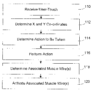
[0056] Reference is now made to Figures 6 to 8 and 9 to describe a method of
controlling an electronic device 20 causing movement of the touch screen
display 24
relative to the base 22 of the portable electronic device 20. Referring first
to Figure 6,
there is shown a sectional side view of portions of the portable electronic
device 20,
according to one embodiment. In the present example, a user touches the touch-
sensitive input surface 28 at the area 91 (Figure 5) of the touch screen
display 24, by
pressing in the direction of the arrow "A" (step 110). The X and Y co-
ordinates of the
location of the touch on the touch-sensitive input surface 28 are determined
at the
controller 30 and the co-ordinates of the touch are provided to the processor
40 (step
112). The processor 40 uses the co-ordinates of the touch to determine the
associated
option or command selected by the user based on the location of the touch
(step 114)
and carries out the appropriate action or actions accordingly (step 116). The
co-ordinates
of the touch are also used by the processor 40 to determine the associated
wire 32b (the
wire 32 to activate) (step 118) and then complete the circuit including the
wire 32b to
cause current flow resulting in a change in shape from the extended spring-
shaped room
temperature state to the compressed spring-shaped heated state (step 120). The
touch
screen display 24 moves as a result of the change in length of the coil-spring
shaped wire
CA 02640831 2008-10-09
32b, as shown in Figure 6. It will be appreciated that the Figures are not to
scale and the
movement of the touch screen display 24 is exaggerated for the purpose of
illustration.
As shown, the touch screen display 24 pivots in the present example to provide
the user
with a tactile response.
5 [0057] Referring now to Figure 7, there is shown a sectional side view of
portions of
the portable electronic device 20, similar to Figure 6. In the present
example, however, a
user touches the touch-sensitive input surface 28 at the area 93 (Figure 5) of
the touch
screen display 24, by pressing in the direction of arrow "B" (step 110). The X
and Y co-
ordinates of the location of the touch on the touch-sensitive input surface 28
are
10 determined at the controller 30 and the co-ordinates of the touch are
provided to the
processor 40 (step 112). The processor 40 uses the co-ordinates of the touch
to
determine the associated option or command selected by the user (step 114) and
carry
out the appropriate action or actions based on the option or command
determined at step
114 (step 116). The co-ordinates of the touch are also used by the processor
40 to
15 determine the associated wire 32d (step 118) to activate and then complete
the circuit
including the wire 32d to cause current flow resulting in a change in shape
from the
extended spring-shaped room temperature state to the compressed spring-shaped
heated state (step 120). The touch screen display 24 moves as a result of the
change in
length of the coil-spring shaped wire 32d, as shown in Figure 7. Again, it
will be
appreciated that the Figures are not to scale and the movement of the touch
screen
display 24 is exaggerated for the purpose of illustration. Again, the touch
screen display
24 pivots in the present example to provide the user with a tactile response.
[0058] Referring now to Figure 8, there is shown a sectional side view of
portions of
the portable electronic device 20, similar to Figures 5 and 6. In the present
example, a
user touches the touch-sensitive input surface 28 at the area 94 (Figure 5) of
the touch
screen display 24, by pressing in the direction of arrow "C" (step 110). The X
and Y co-
ordinates of the location of the touch on the touch-sensitive input surface 28
are
determined at the controller 40 and the co-ordinates of the touch are again
provided to
the processor 40 (step 112) for determining the associated option or command
selected
by the user (step 114) and performing the appropriate actions based on the
option or
command determined at step 114 (step 116). The co-ordinates of the touch are
used by
the processor 40 to determine the associated coil spring wires 32a, 32b, 32c,
32d (step
118) and then complete each of the circuits including the respective coil
spring shaped
wires 32a, 32b, 32c, 32d to cause current flow through each wire 32a, 32b,
32c, 32d
resulting in a change in shape from the extended spring-shaped room
temperature state
to the compressed spring-shaped heated state (step 120). The touch screen
display 24
CA 02640831 2008-10-09
16
moves as a result of the change in length of all of the coil-spring shaped
wires 32a, 32b,
32c, 32d, as shown in Figure 8. Again, it will be appreciated that the Figures
are not to
scale and the movement of the touch screen display 24 is exaggerated for the
purpose of
illustration. In the present example, each of the four wires 32a, 32b, 32c,
32d shrinks
and, rather than pivoting, the touch screen display 24 moves generally
parallel to the
base 22.
[0059] With the movement of the touch screen display 24 relative to the base
22
caused by the phase change in the wire or wires 32a, 32b, 32c, 32d, the user
is provided
with a tactile response during user interaction with the graphical user
interface.
[0060] As indicated above, the touch screen display 24 can be any suitable
touch
screen display and is not limited to a capacitive touch screen display. The
touch screen
display can be, for example, a resistive touch screen display or any other
suitable touch
screen display, as will be appreciated by those skilled in the art.
[0061] As described, the touch screen display 24 is not limited to the
determination of
a single location of a static touch event. Instead, motions such as the
sliding of a finger
along the touch screen display 24 can be determined. Further, it is
contemplated that
touches at more than one location on the touch screen display 24 can be
determined and
motions such as increasing or decreasing the distance between finger touch
locations
can be determined. With more than one location of touch, more than one set of
X and Y
co-ordinates can be used to determine which of the coil-shaped wires 32a, 32b,
32c, 32d
to activate. Thus, more than one of the wires 32a, 32b, 32c, 32d can be
activated without
activating all four of the wires 32a, 32b, 32c, 32d. For example, two of the
wires 32a,
32b, 32c, 32d that are located proximal comers that share a common side can be
activated to cause the touch screen display 24 to pivot. Further still, the
changing location
or motion of the touch can result in a change in activation from one or all of
the coil
shaped wires 32a, 32b, 32c, 32d to another or all of the coil-shaped wires
32a, 32b, 32c,
32d.
[0062] Although five areas are shown in the touch screen display 24 in the
embodiment shown in Figure 5, it will be appreciated that these areas are
shown for
exemplary purposes only and other areas can be employed. For example, the X
and Y
co-ordinates can be determined, followed by activation of the nearest one or
ones of the
four wires 32a, 32b, 32c, 32d. Further, the shape of the areas can differ from
that shown.
Further, a different number of wires can be used and the wires can be located
at different
positions between the base 22 and the touch screen display 24.
[0063] In the embodiments described above, the touch screen display 24 is
framed
by the frame 84, which is fixed to the base 22 by the sidewalls 86. It is
contemplated that
CA 02640831 2008-10-09
17
base 22 can be fixed to the touch screen display 24 by flexible sidewalls
rather than, for
example, rigid sidewalls. Such flexible sidewalls can be made of any suitable
elastomer.
[0064] While the embodiments described herein are directed to particular
implementations of the portable electronic device, it will be understood that
modifications
and variations to these embodiments are within the scope and sphere of the
present
application. For example, the size and shape of many of the features of the
portable
electronic device can differ while still providing the same function. Many
other
modifications and variations may occur to those skilled in the art. All such
modifications
and variations are believed to be within the sphere and scope of the present
application.