Sélection de la langue

Search

Sommaire du brevet 2642635 

Énoncé de désistement de responsabilité concernant l'information provenant de tiers

Une partie des informations de ce site Web a été fournie par des sources externes. Le gouvernement du Canada n'assume aucune responsabilité concernant la précision, l'actualité ou la fiabilité des informations fournies par les sources externes. Les utilisateurs qui désirent employer cette information devraient consulter directement la source des informations. Le contenu fourni par les sources externes n'est pas assujetti aux exigences sur les langues officielles, la protection des renseignements personnels et l'accessibilité.

Disponibilité de l'Abrégé et des Revendications

L'apparition de différences dans le texte et l'image des Revendications et de l'Abrégé dépend du moment auquel le document est publié. Les textes des Revendications et de l'Abrégé sont affichés :

  • lorsque la demande peut être examinée par le public;
  • lorsque le brevet est émis (délivrance).
(12) Brevet: (11) CA 2642635
(54) Titre français: SEPARATEUR A CYCLONE
(54) Titre anglais: CYCLONE SEPARATOR
Statut: Accordé et délivré
Données bibliographiques
(51) Classification internationale des brevets (CIB):
  • B04C 5/181 (2006.01)
  • B04C 5/13 (2006.01)
  • B04C 5/14 (2006.01)
(72) Inventeurs :
  • HANSEN, MORTEN KAARE (Danemark)
(73) Titulaires :
  • FLSMIDTH A/S
(71) Demandeurs :
  • FLSMIDTH A/S (Danemark)
(74) Agent: SMART & BIGGAR LP
(74) Co-agent:
(45) Délivré: 2013-05-21
(86) Date de dépôt PCT: 2006-12-28
(87) Mise à la disponibilité du public: 2007-10-04
Requête d'examen: 2011-12-07
Licence disponible: S.O.
Cédé au domaine public: S.O.
(25) Langue des documents déposés: Anglais

Traité de coopération en matière de brevets (PCT): Oui
(86) Numéro de la demande PCT: PCT/IB2006/055047
(87) Numéro de publication internationale PCT: WO 2007110715
(85) Entrée nationale: 2008-08-15

(30) Données de priorité de la demande:
Numéro de la demande Pays / territoire Date
PA200600416 (Danemark) 2006-03-24

Abrégés

Abrégé français

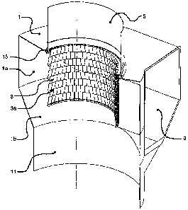
La présente invention concerne un séparateur à cyclone comprenant un logement (1) de cyclone, un conduit d'évacuation (5) et un tube central (3) destiné à dévier les gaz, ledit tube central (3) s'étendant dans le sens axial dans le logement (1) pour cyclone et se composant d'un certain nombre de segments (3a) suspendus à un élément-support (15) placé dans la zone entre le logement (1) pour cyclone et le conduit d'évacuation (5). La particularité du présent séparateur à cyclone réside en ce qu'il comprend un certain nombre de moyens de portage (17) régulièrement répartis et fixés sur le côté intérieur du logement (1) pour cyclone et/ou au conduit d'évacuation (5), et en ce que l'élément-support (15) comprend un disque annulaire ajusté sans serrage sur le dessus des moyens de portage (17) et dont le diamètre extérieur est inférieur au diamètre intérieur du logement (1) et/ou du conduit d'évacuation (5), de manière à ménager un espace (18) entre le disque annulaire (15) et le logement (1) et/ou le conduit d'évacuation (5). On obtient ainsi une réduction importante de la chaleur transmise de l'élément-support au logement du cyclone et/ou au conduit d'évacuation, de sorte que le gradient radial de température dans l'élément-support est réduit d'une température à peu près uniforme sur la section radiale dudit élément. Les contraintes thermiques dans l'élément support sont ainsi sensiblement réduites. Ceci résulte principalement de la réduction de la surface de contact entre l'élément-support et le logement du cyclone et/ou le conduit d'évacuation.


Abrégé anglais

Described is a cyclone separator comprising a cyclone housing (1), a discharge duct (5) and a central tube (3) for diverting gases, said central tube (3) extends axially into the cyclone housing (1) and being composed by a number of segments (3a) which are suspended on a supporting element (15) provided in the area between the cyclone housing (1) and the discharge duct (5). The cyclone separator is peculiar in that it comprises a number of carrying means (17) which are evenly distributed and fixed to the inner side of the cyclone housing (1) and/or the discharge duct (5), and in that the supporting element (15) comprises an annular disc which is loosely fitted on top of the carrying means (17) and having an outer diameter which is smaller than the inner diameter of the cyclone housing (1) and/or the discharge duct (5) so that a clearance (18) is provided between the annular disc (15) and the cyclone housing (1) and/or the discharge duct (5). Hereby is obtained a significant reduction in the heat transmission from the supporting element to the cyclone housing and/or the discharge duct so that the radial temperature gradient in the supporting element is reduced with an approximately uniform temperature over the radial cross section of the element. Hence the thermal stresses in the supporting element will be substantially reduced. This is mainly ascribable to the reduction in the contact area between the supporting element and the cyclone housing and/or the discharge duct.

Revendications

Note : Les revendications sont présentées dans la langue officielle dans laquelle elles ont été soumises.


5
Claims
1. A cyclone separator comprising a cyclone housing (1), a discharge duct (5)
and a central tube (3) for diverting gases, said central tube (3) extends
axially
into the cyclone housing (1) and being composed by a number of segments (3a)
which are suspended on a supporting element (15) provided in the area between
the cyclone housing (1) and the discharge duct (5), characterized in that it
comprises a number of carrying means (17) which are evenly distributed and
fixed to the inner side of the cyclone housing (1) and/or the discharge duct
(5),
and in that the supporting element (15) comprises an annular disc which is
loosely fitted on top of the carrying means (17) and having an outer diameter
which is smaller than the inner diameter of the cyclone housing (1) and/or the
discharge duct (5) so that a clearance (18) is provided between the annular
disc
(15) and the cyclone housing (1) and/or the discharge duct (5).
2. Cyclone separator according to claim 1, characterized in that the carrying
means (17) are configured as shelf brackets having a substantially triangular
shape.
3. Cyclone separator according to claim 2, characterized in that the carrying
means (17) are fixed to the cyclone housing (1) and/or the discharge duct (5)
by
welding.
4. Cyclone separator according to claim 1, characterized in that the annular
disc
(15) is configured with an upwardly protruding flange (16).
5. Cyclone separator according to claim 4, characterized in that the upwardly
protruding flange (16) of the annular disc (15) is divided into a number of
segments (16a).

6
6. Cyclone separator according to claim 4, characterized in that the annular
disc (15) is
provided with a heat-insulating layer on its upper side.
7. Cyclone separator according to claim 4, characterized in that the annular
disc (15) with
its upwardly protruding flange (16) and the shelf brackets (17) are made of
heat-
resistant steel.
8. Cyclone separator according to any one of claims 1 to 7, characterized in
that the
cyclone separator is lined.

Description

Note : Les descriptions sont présentées dans la langue officielle dans laquelle elles ont été soumises.


CA 02642635 2008-08-15
WO 2007/110715 PCT/IB2006/055047
1
CYCLONE SEPARATOR
The present invention relates to a cyclone separator comprising a cyclone
housing, a discharge duct and a central tube for diverting gases, said central
tube
extends axially into the cyclone housing and being composed by a number of
segments which are suspended on a supporting element provided in the area
between the cyclone housing and the discharge duct.
Cyclone separators are generally known and widely used for many different
technical applications in which two phases such as gases and material
particles
in suspension are to be separated. Cyclones typically comprise a cyclone
housing with an upper substantially cylindrical part and a lower conical part,
an
often tangential inlet in the upper part of the cyclone housing for
introducing the
suspension which is to be separated, an outlet at the bottom of the conical
part
for diverting one fraction of the suspension, as well as a central tube
extending
with a free end axially into the cyclone housing for diverting the second
fraction of
the suspension via a discharge duct.
From US patent No. 4,505,051 is known an example of a cyclone separator of
the aforementioned kind. In this known cyclone separator the upper row of the
segments of the central tube comprises an L-shaped part which protrudes
outwards and downwards and which rests against a supporting element which is
formed with an upwardly projecting part and which is rigidly connected by
welding
to the cyclone housing/discharge duct. In instances where the cyclone
separator
is used to separate hot material/gas suspensions, for example in connection
with
the heating of cement raw materials for cement manufacture, where the
temperature may reach a level as high as 9002 C, the heat impact on the
central
tube will be quite significant, leading to changes in the transverse
dimensions. It
is a particular feature of the known cyclone separator according to US patent
4,505,051 that, in order to prevent serious damage to the central tube, the
special suspension of the segments of the central tube on the supporting
elements takes due account of the fact that the central tube is affected by
such

CA 02642635 2008-08-15
WO 2007/110715 PCT/IB2006/055047
2
changes of transverse dimensions because of the heat impact. For the known
cyclone separator, the heat transmission from the central tube via the
supporting
element to the cyclone housing/discharge duct will, however, be quite
significant
due to the relatively large contact surfaces existing between these structural
elements. As a consequence of this, a radial temperature gradient may occur in
the supporting element ranging from a level around 6002C at the innermost part
of the element to around 2002 C at the outermost part of the element. A radial
temperature gradient of this magnitude in the supporting element will give
rise to
significant thermal stress loads which under adverse circumstances may exceed
the yield stress limit of the steel used, and involving, in worst-case
scenario, a
risk the central tube collapsing.
It is the object of the present invention to provide a cyclone separator by
means
of which the aforementioned disadvantage is significantly reduced.
This is obtained according to the invention by a cyclone separator of the kind
mentioned in the introduction, and being characterized in that it comprises a
number of carrying means which are evenly distributed and fixed to the inner
side
of the cyclone housing and/or the discharge duct, and in that the supporting
element comprises an annular disc which is loosely fitted on top of the
carrying
means and having an outer diameter which is smaller than the inner diameter of
the cyclone housing and/or the discharge duct so that a clearance is provided
between the annular disc and the cyclone housing and/or the discharge duct.
Hereby is obtained a significant reduction in the heat transmission from the
supporting element to the cyclone housing and/or the discharge duct so that
the
radial temperature gradient in the supporting element is reduced with an
approximately uniform temperature over the radial cross section of the
element.
Hence the thermal stresses in the supporting element will be substantially
reduced. This is mainly ascribable to the reduction in the contact area
between
the supporting element and the cyclone housing and/or the discharge duct.

CA 02642635 2008-08-15
WO 2007/110715 PCT/IB2006/055047
3
The carrying means may be configured in any appropriate manner but for
optimization of strength characteristics it is preferred that they are
configured as
shelf brackets having a substantially triangular shape.
The shelf brackets may be fixed to the cyclone housing and/or the discharge
duct
in any appropriate manner but it is preferred that they are fixed by welding.
The annular disc which forms the supporting element may be configured with an
upwardly protruding flange in order to improve the fixation of the central
tube
segments which are typically formed with a corresponding downwardly protruding
flange. In order to limit the thermal stresses in the upwardly protruding
flange of
the annular disc, the flange is preferentially divided into a number of
segments.
The annular disc may also be provided with a heat-insulating layer on its
upper
side in order to reduce the heat transmission from the central tube.
It is preferred that the annular disc with its upwardly protruding flange and
the
shelf brackets are made of heat-resistant steel.
It is further preferred that the cyclone separator is lined in traditional
manner.
The invention will now be described in further details with reference to the
drawing, where
Fig. 1 shows a partial cut-through view of a cyclone separator comprising a
central tube according to a preferred embodiment of the invention, and
Fig. 2 shows details at the cyclone separator shown in Fig. 1.

CA 02642635 2008-08-15
WO 2007/110715 PCT/IB2006/055047
4
In Fig. 1 and 2 is seen a cyclone separator comprising a cyclone housing 1.
The
cyclone housing 1 has an upper cylindrical part 1 a and a lower conical part 1
b, a
tangential inlet 9 for introducing the suspension to be separated, an outlet
11 at
the bottom of the conical part for diverting one fraction of the suspension,
as well
as a central tube 3 which extends axially into the cyclone housing 1 for
diverting
the second fraction of the suspension via a discharge duct 5.
The central tube 3 is made up of a number of segments 3a which are suspended
on a supporting element 15 at the upper end of the cyclone housing 1. The
supporting element 15 comprises an upwardly protruding flange 16 which, as
shown, is divided into segments 16a.
According to the invention the cyclone separator comprises a number of
carrying
means 17, here shown by way of shelf brackets 17 which are fixed, evenly
distributed, to the lowermost part of the inner side of the discharge duct 5.
The
supporting element in the form of an annular disc 15 is loosely fitted on the
shelf
brackets 17, allowing the disc to move relative to the shelf brackets 17. The
annular disc 15 is formed with an outer diameter which is smaller than the
inner
diameter of the discharge duct 5 thereby creating a clearance 18 between the
annular disc 15 and discharge duct 5.
As mentioned in the introduction the heat transmission from the annular disc
15
via the shelf brackets 17 to the discharge duct 5 will thus be substantially
reduced because of the reduction in the contact area so that the annular disc
15
has an approximately uniform temperature across its radial cross-section,
hence
being subjected to substantially reduced thermal stresses.

Dessin représentatif
Une figure unique qui représente un dessin illustrant l'invention.
États administratifs

2024-08-01 : Dans le cadre de la transition vers les Brevets de nouvelle génération (BNG), la base de données sur les brevets canadiens (BDBC) contient désormais un Historique d'événement plus détaillé, qui reproduit le Journal des événements de notre nouvelle solution interne.

Veuillez noter que les événements débutant par « Inactive : » se réfèrent à des événements qui ne sont plus utilisés dans notre nouvelle solution interne.

Pour une meilleure compréhension de l'état de la demande ou brevet qui figure sur cette page, la rubrique Mise en garde , et les descriptions de Brevet , Historique d'événement , Taxes périodiques et Historique des paiements devraient être consultées.

Historique d'événement

Description Date
Représentant commun nommé 2019-10-30
Requête pour le changement d'adresse ou de mode de correspondance reçue 2018-01-12
Accordé par délivrance 2013-05-21
Inactive : Page couverture publiée 2013-05-20
Inactive : Taxe finale reçue 2013-03-05
Préoctroi 2013-03-05
Un avis d'acceptation est envoyé 2013-02-04
Lettre envoyée 2013-02-04
Un avis d'acceptation est envoyé 2013-02-04
Inactive : Approuvée aux fins d'acceptation (AFA) 2013-02-01
Modification reçue - modification volontaire 2012-12-17
Inactive : Dem. de l'examinateur par.30(2) Règles 2012-11-01
Lettre envoyée 2011-12-20
Exigences pour une requête d'examen - jugée conforme 2011-12-07
Toutes les exigences pour l'examen - jugée conforme 2011-12-07
Modification reçue - modification volontaire 2011-12-07
Requête d'examen reçue 2011-12-07
Inactive : Page couverture publiée 2008-12-18
Inactive : Notice - Entrée phase nat. - Pas de RE 2008-12-15
Inactive : CIB en 1re position 2008-12-03
Demande reçue - PCT 2008-12-02
Inactive : Déclaration des droits - PCT 2008-08-26
Exigences pour l'entrée dans la phase nationale - jugée conforme 2008-08-15
Demande publiée (accessible au public) 2007-10-04

Historique d'abandonnement

Il n'y a pas d'historique d'abandonnement

Taxes périodiques

Le dernier paiement a été reçu le 2012-12-07

Avis : Si le paiement en totalité n'a pas été reçu au plus tard à la date indiquée, une taxe supplémentaire peut être imposée, soit une des taxes suivantes :

  • taxe de rétablissement ;
  • taxe pour paiement en souffrance ; ou
  • taxe additionnelle pour le renversement d'une péremption réputée.

Veuillez vous référer à la page web des taxes sur les brevets de l'OPIC pour voir tous les montants actuels des taxes.

Titulaires au dossier

Les titulaires actuels et antérieures au dossier sont affichés en ordre alphabétique.

Titulaires actuels au dossier
FLSMIDTH A/S
Titulaires antérieures au dossier
MORTEN KAARE HANSEN
Les propriétaires antérieurs qui ne figurent pas dans la liste des « Propriétaires au dossier » apparaîtront dans d'autres documents au dossier.
Documents

Pour visionner les fichiers sélectionnés, entrer le code reCAPTCHA :


Pour visualiser une image, cliquer sur un lien dans la colonne description du document. Pour télécharger l'image (les images), cliquer l'une ou plusieurs cases à cocher dans la première colonne et ensuite cliquer sur le bouton "Télécharger sélection en format PDF (archive Zip)" ou le bouton "Télécharger sélection (en un fichier PDF fusionné)".

Liste des documents de brevet publiés et non publiés sur la BDBC .

Si vous avez des difficultés à accéder au contenu, veuillez communiquer avec le Centre de services à la clientèle au 1-866-997-1936, ou envoyer un courriel au Centre de service à la clientèle de l'OPIC.


Description du
Document 
Date
(aaaa-mm-jj) 
Nombre de pages   Taille de l'image (Ko) 
Description 2008-08-15 4 170
Revendications 2008-08-15 2 48
Dessins 2008-08-15 1 32
Abrégé 2008-08-15 1 74
Dessin représentatif 2008-12-16 1 14
Page couverture 2008-12-18 2 62
Revendications 2012-12-17 2 47
Page couverture 2013-05-01 2 63
Avis d'entree dans la phase nationale 2008-12-15 1 194
Rappel - requête d'examen 2011-08-30 1 122
Accusé de réception de la requête d'examen 2011-12-20 1 177
Avis du commissaire - Demande jugée acceptable 2013-02-04 1 162
Correspondance 2008-08-26 2 44
PCT 2008-08-15 4 134
Taxes 2009-11-17 1 34
Taxes 2010-11-18 1 35
Correspondance 2013-03-05 1 50