Note : Les descriptions sont présentées dans la langue officielle dans laquelle elles ont été soumises.
CA 02643647 2008-11-12
INTERFACE CONNECTOR FOR A MOTOR AND
A MOTOR INCORPORATING THE INTERFACE CONNECTOR
RELATED APPLICATIONS
This application claims the benefit of U.S. Provisional Patent application No.
60/991,387, filed on November 30, 2007, the content of which is incorporated
by reference in
its entirety.
BACKGROUND
[0001] The invention relates to electrical connectors for interfacing power
and/or signal
conductors between a first apparatus and an electric motor.
[0002] In many cases, the electrical connection for an electric motor is a
wiring harness
(or "pigtail") emerging from the motor housing through a grommet. Wiring
connections of
this type are disadvantageous in that the wires may become tangled or broken
during
installation of the motor. Additionally, the wiring harness is often attached
to a circuit board
within the motor enclosure. If the wiring harness becomes ensnared during
installation, the
wiring harness may become disconnected from the circuit board, ruining the
motor.
SUMMARY
[0003] In one embodiment, the invention provides an interface connector
comprising a
body and a plurality of conductors, each conductor having a tab end and a pin
end. One
side of the body has a plurality of recessed openings, and the conductors are
partially
embedded in the body such that the tab end of each conductor is located in a
respective
recessed opening. According to this embodiment, the pin ends protrude from
another side
of the body, thereby allowing the pin ends to be interfaced to a circuit board
or some other
means of making electrical connections. Because the body is made of an
insulating
material, each conductor remains electrically isolated from the other
conductors.
[0004] In some embodiments, the motor interface connector has one or more
slots
molded into the body so that the interface connector receives mounting
surfaces of first and
second portions of a motor housing, wherein the first and second portions of
the motor
housing can be assembled to produce an enclosure for a motor. Optionally, the
interface
connector may be soldered to a circuit board. In the event the interface
connector is
soldered to a circuit board, the circuit board and interface connector may be
disposed into a
first portion of the motor housing, and then the circuit board, connector and
first portion of
1
CA 02643647 2008-11-12
the motor housing may be assembled with the second portion of the motor
housing to make
a complete enclosure for a motor. Thus, the enclosure for the motor can hold
the interface
connector securely in place with respect to the circuit board.
[0005] In another embodiment, the invention provides for an electric motor
comprising
an interface connector comprising a body and a plurality of conductors, each
conductor
having a tab end and a pin end. One side of the body has a plurality of
recessed openings,
and the conductors are partially embedded in the body such that the tab end of
each
conductor is located in a respective recessed opening. The electric motor may
optionally
have a circuit board contained inside a motor housing. The interface connector
provides, in
one implementation, a way to interface external power and control circuitry to
the electric
motor.
[0006] Other aspects of the invention will become apparent by consideration of
the
detailed description and accompanying drawings.
BRIEF DESCRIPTION OF THE DRAWINGS
[0007] FIG. 1 is a perspective view of an embodiment of an interface connector
of the
invention.
[0008] FIG. 2 is a front view of the interface connector shown in FIG. 1.
[0009] FIG. 3 is a sectional view of the interface connector shown in FIG. 1.
[0010] FIG. 4 is a bottom view of the interface connector shown in FIG. 1.
[0011] FIG. 5 is a partial exploded view of a portion of a motor assembly,
including the
interface connector shown in FIG. 1.
[0012] FIG. 6 is a partial exploded view of a motor assembly, including the
portion of the
motor assembly shown in FIG. 5.
DETAILED DESCRIPTION
[0013] Before any embodiments of the invention are explained in detail, it is
to be
understood that the invention is not limited in its application to the details
of construction and
the arrangement of components set forth in the following description or
illustrated in the
following drawings. The invention is capable of other embodiments and of being
practiced or
of being carried out in various ways. Also, it is to be understood that the
phraseology and
terminology used herein is for the purpose of description and should not be
regarded as
2
CA 02643647 2008-11-12
limiting. The use of "including," "comprising," or "having" and variations
thereof herein is
meant to encompass the items listed thereafter and equivalents thereof as well
as additional
items. Unless specified or limited otherwise, the terms "mounted,"
"connected," "supported,"
and "coupled" and variations thereof are used broadly and encompass both
direct and
indirect mountings, connections, supports, and couplings. Further, "connected"
and
"coupled" are not restricted to physical or mechanical connections or
couplings.
[0014] Although directional references (e.g., front, rear, behind, etc.) may
be made
herein in describing the drawings, these references are made relative to the
drawings (as
normally viewed) for convenience. These directions are not intended to be
taken literally or
limit the invention in any form. In addition, terms such as "first," "second,"
and "third" are
used herein for purposes of description and are not intended to indicate or
imply relative
importance or significance.
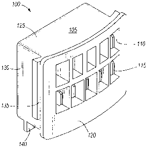
[0015] FIGS. 1 and 2 show an interface connector 100. Interface connector 100
is
comprised of a body 105 with recessed openings 110, and conductors 115
partially
embedded in body 105. Body 105 is a single contiguous piece in that it is not
constructed
from multiple pieces, but rather comprises a unitary piece of material. Body
105 may be
constructed from insulating materials including, but not limited to,
acrylonitrile butadiene
styrene (ABS), polyethylene, polyvinyl chloride, nylon and
polytetrafluoroethylene.
Conductors 115 may be constructed from a number of conducting materials,
including, but
not limited to, copper, aluminum, and alloys comprising copper and aluminum.
As shown in
FIG. 1, interface connector 100 has a front 120, a top 125, and a side 130.
Interface
connector 100 may optionally have a slot 135 in side 130 such that body 105
receives into a
mounting surface 230 (shown in FIG. 6) of a second portion 225 of a motor
housing (shown
in FIG. 6). Body 105 may also have a stand 140 to provide additional
structural
reinforcement once interface connector 100 has been attached to a circuit
board 160 (shown
in FIG. 5). Stand 140 may additionally assist in the location of interface
connector 100
during assembly of an electric motor.
[0016] Recessed openings 110 are visible in front 120 of interface connector
100.
According to the invention, tab ends 145 of conductors 115 are arranged within
at least
some of recessed openings 110. This arrangement allows tab ends 145 to be
individually
indexed to mate with protrusions from a mating connector having a plurality of
conductor tab
receptacles (not shown). Tab ends 145 may vary in size and shape for
convenience or to
assure that power connections and signal connections are not crossed. For
example, tab
ends 145 may be rectangular in shape, or have beveled edges, or may be rounded
to mate
with tab receptacles (not shown). A particular combination of tab end shapes
and sizes may
3
CA 02643647 2008-11-12
be advantageous in assuring that various power and/or control wiring is not
crossed.
Additionally, interface connector 100 may be produced with one or more of the
recessed
openings 110 without a tab end 145, thus creating a blank opening 150 which
may act as a
reference point for the mating connector, which may be substantially
symmetric.
[0017] Conductors 115 additionally have pin ends 155, which are seen in FIG. 2
as
protruding from a bottom 160 of interface connector 100. Pin ends 155 may be
arranged in
front of stand 140, as shown, or behind stand 140, or straddling stand 140 as
the needs of
interface connector 100 dictate. Pin ends 155, may comprise a variety of
shapes and sizes,
such as round, square, rectangular, or triangular, in order to mate each pin
end 155 with the
appropriate internal connection (not shown).
[0018] FIG. 3 is a sectional view of interface connector 100, taken along the
cut-line 3-3
shown in FIG. 2. As can be seen in FIG. 3, body 105 holds conductors 115,
providing
insulation between conductors 115 and providing structural support. As shown
in FIG. 3,
conductor 115 is a continuous piece having tab end 145 and pin end 155. Tab
ends 145 are
connected to pin ends 155 that may be connected to a circuit board 180 (shown
in FIG. 5).
As shown in FIG. 3, conductors 115 may be substantially "L" shaped, however
other shapes
may be used as the arrangement of interface connector 100 require. Other
shapes and
designs for conductors 115 are possible. For example, conductor 115 may be "S"
or "I"
shaped depending upon the orientation of the final connection to pin ends 155.
An
additional slot 165 for receiving into a mounting surface 170 (shown in FIG.
5) in a first
portion 175 (shown in FIG. 5) of a motor housing is also visible.
[0019] FIG. 4 is a view of bottom 160 of interface connector 100 and shows
detail of pin
ends 155. FIG. 4 also shows an optional configuration of stand 140, as well as
additional
slot 165 for receiving a mounting surface 170 (shown in FIG. 5) in a first
portion 175 (shown
in FIG. 5) of a motor housing. The curvature of the front 120 of interface
connector 100 and
additional slot 165 match the curvature of mounting surface 170 (shown in FIG.
5).
Additional slot 165 need not be curved, and typically will be formed to match
the shape of
the motor housing. For example, additional slot 165 may be substantially
straight if the
motor housing is square.
[0020] FIG. 5 is a partial exploded view of a portion of a motor assembly 190,
including
interface connector 100, circuit board 180, and the first portion 175 of a
motor housing.
Interface connector 100 will typically be disposed upon circuit board 180,
such that pin ends
155 align with holes 195 of circuit board 180. Pin ends 155 may be optionally
soldered to
circuit board 180 such that each pin end 155 is connected to the appropriate
circuit on circuit
4
CA 02643647 2008-11-12
board 180. Other methods of attaching pin ends 155 to circuit board 180 are
known, such
as glue, epoxy, or metal fasteners. In the event that interface connector 100
is disposed
upon circuit board 180, circuit board 180 with attached interface connector
100 may be
together disposed into first portion 175 of a motor housing, with care being
taken that
additional slot 165 in bottom 160 receives mounting surface 170. Stand 140 may
be used to
establish a minimum clearance between bottom 160 (not shown) and circuit board
180.
Other equivalent techniques for assembling may be used, for example circuit
board 180 may
first be disposed into first portion 175 of a motor housing, and then
interface connector 100
attached thereto.
[0021] FIG. 6 is a partial exploded view of a motor assembly 200 including
portion of a
motor assembly 190 shown in FIG. 5, a bottom bracket 205, a stator 210, a
rotor 215, a shaft
220, and a second portion 225 of a motor housing. After bottom bracket 205,
stator 210,
rotor 215, and shaft 220 are disposed into second portion 225 of a motor
housing, portion of
the motor assembly 190 is attached to second portion 225 of a motor housing.
Slots 135
receive a mounting surface 230 in second portion 225 of the motor housing,
thus ensuring
the mechanical stability of the interface connector 100. Portion of a motor
assembly 190
may be attached to second portion 225 of the motor housing by way of fasteners
extending
through guide posts 235 of first portion 175 of a motor housing. However,
other methods of
attaching portion of a motor assembly 190 to second portion 225 of motor
housing are
known.
[0022] The motor interface connector of the invention can be used to provide
an external
interface for a control and/or power circuit of an electric motor. Interface
connectors are
typically used in electric motors that are incorporated into mechanical
devices, including, but
not limited to, furnaces, blowers, or pumps. Such motors are typically under
50 hp,
preferably under 20 hp, more preferably under 10 hp. Motors incorporating the
interface
connector of the invention may be sold as part of a new mechanical device, or
the motor
may be sold as an aftermarket replacement for motors of similar size and
power.
[0023] The interface connector allows an electric motor to have a streamlined
profile, as
there are no dangling connectors. This profile is especially beneficial when
the motors are
sold as aftermarket replacements because there are fewer concerns about wires
being
crimped or broken during shipping and installing. Additionally, motors
incorporating an
interface connector of the invention may be able to fit into tighter spaces,
because there are
no wires emerging from the motor housing.
CA 02643647 2008-11-12
Thus, the invention provides, among other things, a new and useful interface
connector for a motor and a motor incorporating the interface connector.
6