Note : Les descriptions sont présentées dans la langue officielle dans laquelle elles ont été soumises.
CA 02644792 2008-10-27
Derek Foran page 2
SPECIFICATION
TECHNICAL FIELD:
This invention is a specific structure which has as its purpose the production
of electrical power
by the capture of tidal kinetic energy.
BACKGROUND INFORMATION:
There are two general ways in which power may be produced from tides: by the
use of
impoundment ponds (capture of potential energy) and by placing water turbines
directly in
tidal currents (capture of kinetic energy).
The first way, impoundment ponds, involves the gradual capture and release of
water. By
opening and closing the entry to the pond, a water height differential between
the ocean and
pond can be established. This differential is then used to allow water to
fall, driving turbines
and producing power. There are many different tidal power plants, including
those of Canadian
patent 1170960, filed September 14 1982, and Canadian patent 2537578, filed
July 10 2004,
which use variations of this method. Although existing tidal power plants
utilizing
impoundment ponds have been successful in producing power from the energy of
the tides,
they do face problems, most notably high cost and lack of adequate power plant
locations.
The first problem, high cost, is mainly due to the large expenses in
constructing the
containment walls of the impoundment ponds. Similarly to hydroelectric dams,
these
containment walls must be very thick and able to support great loads caused by
the water level
differentials between pond and ocean. The installation and materials costs of
these walls can
prevent the construction of a tidal power station from being economically
viable.
The second problem, lack of proper locations, is due to the very specific
physical conditions
which many tidal power plants need to be economically and environmentally
viable. Ideally,
most containment pond tidal power stations are located in an inlet to reduce
the length of the
containment walls and subsequent costs. Although inlets of correct dimensions
for
impoundment pond power stations are fairly common, they must also be located
in a
geographical area with large high to low tide differentials. Locations
satisfying both these
previous conditions are rare thus limiting the widespread use of tidal power
stations. Some
tidal power plants, such as that of Canadian patent 2537578, try to deal with
the limited
amount of viable locations by making it possibie for the plant to be located
offshore or simply
along the coast (not necessarily in an inlet). These power stations solve the
problem of having a
limited amount of proper inlets - however another problem is created. By doing
this, they
increase the size of the containment walls needed and the economic viability
of constructing
CA 02644792 2008-10-27
Derek Foran page 3
the power station is lowered.
Another problem that all tidal power stations have to deal with is their
destructive impact on
the environment. Coastal tidal power stations are especially problematic
because they have a
profound negative effect on coastal ecosystems which can often be very
sensitive. By placing
the station offshore, the negative environmental impact, though not totally
eliminated, can be
reduced.
So far we have seen that tidal power stations using impoundment ponds face
many problems
including: high cost, lack of proper locations and negative impact on the
environment. The
second way of extracting energy from the tides is to place water turbines
directly in tidal
currents (subsequently we will call this the direct current turbine method).
This method has
been widely used and is probably the simplest type of tidal power plant. Like
impoundment
ponds, turbines placed directly in tidal currents have their advantages and
disadvantages. The
direct current turbine method usually costs less to construct than a large
scale impoundment
pond because of the lack of expensive containment walls. Despite this, many
possible direct
current turbine placements are not economically viable because the magnitudes
of the tides,
and the subsequent power output of the turbines, are not high enough to offset
construction
costs and maintenance of the turbines. This fact has limited the construction
of direct current
turbines to locations where the timing and magnitudes of the currents are near
ideal. There
are simply not enough suitable locations in the world to make direct current
turbines a
substantial source of power. Another problem that arises with direct current
turbines, similarly
to impoundment ponds, is their negative impact on wildlife. Though they do not
greatly
interfere with nature due to sheer size like impoundment ponds, they can have
severe
negative environmental impacts because they are in direct contact with aquatic
species. In
direct current turbines there is nothing separating the turbines from the open
ocean therefore
it would be possible for ocean creatures such as whales, seals and fish to be
injured by the
turbines or have their breeding and feeding grounds disturbed.
As we have seen, both the impoundment pond and direct current turbine methods
face
problems of cost, location and environmental impact. The tidal power plant of
Canadian patent
2537578 and others acknowledge these problems and try to fix them.
Canadian patent 2537578 attempts to solve the environmental problem of having
a tidal
power plant in an estuary or along a shoreline by providing the alternative of
locating the plant
entirely offshore. Although this avoids problems associated with coastal
ecosystems, the tidal
power plant remains an impoundment pond and thus a large structure. The local
ecosystem
would be negatively affected simply because of the imposing size of the tidal
power plant. A
reduction in the size of the tidal power plant would be necessary to reduce
its intrusive impact
CA 02644792 2008-10-27
Derek Foran page 4
on the local ecosystem. An environmental problem that all tidal power plants
face is the
possibility of ocean creatures such as whales, seals and fish being injured by
the turbines of the
plant. Although this problem would be more prominent with direct current
turbines because
they are in the open ocean, it could also occur with impoundment ponds.
Impoundment pond
tidal power plants have dealt with this possible problem by separating the
turbines from the
open ocean with grates and nets, similarly to hydroelectric dams. The
environmental problem
still remains with direct current turbines however because the turbines are
open to the ocean.
To increase the amount of potential tidal power plant sites, Canadian patent
2537578
proposes the possibility of locating its plant entirely offshore. Although
this method does
increase the amount of potential sites, it brings about higher construction
costs due to the
increased length in containment walls. Tidal power plants using the direct
current turbine
method face a different problem with location which is the insufficiency of
locations with
currents of correct timing and large enough magnitude. Turbine designers have
tried to
increase the amount of viable locations by increasing the efficiency of the
turbines but this has
not been enough to make direct current turbines a large provider of global
power. It is clear
from the location problems of both impoundment ponds and direct current
turbines that the
amount of tidal power plants can only increase if the plants can become more
cost effective in
their specific locations.
To reduce construction costs compared to previous impoundment pond structures,
Canadian
patent 2537578 proposes a method called Modular Barrier Construction. The
patent claims
that using this method reduces the materials and time needed to build the
containment walls,
thus reducing costs. Even if the claims of Canadian patent 2537578 regarding
Modular Barrier
Construction are true, the fact remains that the design is a type of
impoundment pond,
needing a great length of containment walls because it is a closed structure.
Due to the fact
that the length of the containment walls directly affects costs, it is obvious
that reducing the
length of the walls would be needed to lower construction and materials costs.
The fact that
Canadian patent 2537578 is an impoundment pond also means that the containment
walls
must be able to support great loads caused by water level differentials.
Because of the great
amount of forces that they must withstand, the walls must be thick and thus
construction is
expensive. Containment walls with less force exerted on them (not affected by
water level
differentials) wouldn't need to be as thick and therefore would be less
expensive.
The economic viability of a tidal power plant isn't only determined by the
construction costs
but by the relationship between the total costs of the plant (construction,
maintenance, etc.)
and the total power output of the plant. Many impoundment pond tidal power
plants fail to
CA 02644792 2008-10-27
Derek Foran page 5
increase their economic viability because they don't take advantage of the
kinetic energy of
tidal flows. Canadian patent 2537578 recognises this problem and attempts to
fix it by shaping
sections of the containment walls to capture the kinetic energy of tidal
currents. Although this
improves on earlier impoundment pond tidal power plants, Canadian patent
2537578 fails to
take full advantage of the kinetic energy of tides. The shaped sections of the
containment walls
are designed only for one-way capture of tidal kinetic energy therefore not
taking advantage of
both the flooding and ebbing of the tides. A two-way tidal current capturing
structure would
clearly be better at capturing the maximum amount of kinetic energy from the
tides. Canadian
patent 2537578 faces another problem when it comes to implementing tidal
kinetic energy
capturing devices which is that it is not specialised for such. The tidal
kinetic energy aspect of it
is dependent on the entire structure which is large and expensive. Also, the
rest of the
structure has its own set of location criteria which may not match that of its
kinetic tidal energy
aspect. Because of this, it is unlikely that the tidal power plant would be
able to take full
advantage of the kinetic energy aspect of tidal flows. A tidal power plant
made uniquely for the
capture of tidal kinetic energy would be more cost effective in this regard
because its structure
and location could be optimized for capturing kinetic energy of tidal flows.
Despite the efforts of previous inventors, tidal power plants continue to face
environmental,
location and cost problems. The Tidal Energy Structure that is suggested in
this patent manages
to overcome the problems faced by both impoundment ponds and water turbines
placed
directly in tidal currents.
SOLUTIONS FOR ENVIRONMENTAL PROBLEMS
= The Tidal Energy Structure eliminates the environmental problem of having
the plant
in an estuary or along shore by having its location entirely offshore.
= The Tidal Energy Structure needs not be as large as offshore or shoreline
impoundment ponds thus reducing its intrusive impact on the local ecosystem.
= The Tidal Energy Structure eliminates the problem of ocean creatures being
injured
or killed by the turbines of the plant by separating the turbines from the
open ocean
with nets and containment walls.
= The Tidal Energy Structure reduces the potential of any long term
environmental
damage due to the fact that the structure is relatively easy to disassemble.
SOLUTIONS FOR LOCATION PROBLEMS
0 The Tidal Energy Structure can be located entirely offshore thus increasing
the
CA 02644792 2008-10-27
Derek Foran page 6
amount of possible locations versus tidal power plants needing to be located
on
specific shorelines or in estuaries.
= The Tidal Energy Structure increases the amount of locations with sufficient
tidal
currents by increasing the magnitude of the currents themselves.
= The Tidal Energy Structure only captures tidal kinetic energy (not tidal
potential
energy) therefore its location is not limited by the location criteria of
other energy
capturing methods such as impoundment ponds.
SOLUTIONS FOR COST PROBLEMS
= The containment walls of the Tidal Energy Structure do not have to withstand
as
much force as those of impoundment ponds because there is no water level
differential. Due to this, the walls of the Tidal Energy Structure do not have
to be as
thick which saves on construction and materials costs.
= The containment walls of the Tidal Energy structure can be made of resistant
flexible
sheets strung between supporting posts driven into the ground. The methods of
installing this and the materials used are much cheaper than cement or rock
containment walls and thus could reduce on construction and materials costs.
= The containment walls of the Tidal Energy Structure are much less thick than
those
of impoundment ponds. This makes them easier to install which reduces the
amount
of time and money needed for construction.
= The Tidal Energy Structure is not a large closed structure such as an
impoundment
pond tidal power plant therefore the length of the containment walls and
subsequent costs are greatfy reduced.
= The Tidal Energy Structure increases its economic viability by increasing
the
magnitude of the tidal currents entering the turbines. This is done by shaping
the
containment walls to funnel the tidal currents into the turbine area. This
captures
the kinetic energy of a larger area and provides more power output than
traditional
direct current turbines.
= The Tidal Energy Structure incorporates a two way capture of kinetic energy
(flooding and ebbing of the tides) which greatly increases its power output
and
economic viability.
= The Tidal Energy Structure is made uniquely for the capture of tidal kinetic
energy
CA 02644792 2008-10-27
Derek Foran page 7
(not tidal potential energy) therefore its economic viability is not dependent
on
other energy capturing elements which can be large and expensive.
DRAWINGS
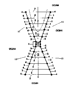
Figure 1: Illustrates from a top plan view the Tidal Energy Structure with
some of its main
components in a section of open ocean.
Figure 2: Illustrates a perspective view from the front of one of two openings
where the tidal
currents enter the Tidal Energy Structure.
Figure 3: Illustrates a vertical section of the preferred embodiment of the
turbine
compartment located in the middle of the Tidal Energy Structure. This
compartment is referred
to as element 6 in figure 1.
Figure 4: Illustrates a vertical section of an alternative turbine compartment
located in the
middle of the Tidal Energy structure. This compartment is referred to as
element 6 in figure 1.
REFERENCE NUMBERS OF EACH ELEMENT
1: Tidal currents entering the turbines
2: Tidal currents exiting the turbines
3: Turbine apparatus
4: Supporting post
5: Containment panel for containment wall structure
6: Turbine compartment
7: Docking and maintenance station
8: Horizontal support wire
9: Net and horizontal support wire apparatus
10: Entire structure of a containment wall
11: Containment panel for turbine compartment
12: Turbine generator
CA 02644792 2008-10-27
Derek Foran page 8
13: Turbine rotor blades
14: Pivoting turbine attachment point
15: Transformer and control panel
16: Protective top covering for turbine compartment
17: Containment barrier
18: Turbine rotor shaft
19: Bottom rim section
DETAILED DESCRIPTION: PREFERRED EMBODIMENTS
The present invention will now be described more fully hereinafter with
reference to the
accompanying drawings, in which preferred embodiments of the invention are
shown. This
invention may, however, be embodied in many different forms and should not be
construed as
limited to the embodiments set forth herein. Rather, these embodiments are
provided so that
this disclosure will be thorough and complete, and will fully convey the scope
of the invention
to those skilled in the art.
Figure 1 illustrates from the top plan view the Tidal Energy Structure with
some of its main
components in a section of open ocean. The containment wall structures (10),
which are
arranged in an hourglass shape, funnel the incoming tidal currents (1) into
the turbine
compartment (6) where the tidal kinetic energy is captured by the turbine
apparatus (3). The
tidal currents going out (2) of the turbine compartment (6) and Tidal Energy
Structure are of
significantly less magnitude than those coming in (1) due to the fact that the
turbine apparatus
(3) captures some of the tidal kinetic energy. The Tidal Energy Structure is
capable of capturing
tidal kinetic energy from both the flooding and ebbing of the tides therefore
the direction of
incoming (1) and outgoing (2) tidal currents illustrated in figure 1 will be
reversed depending
on the direction of the tide. The preferred location of the Tidal Energy
Structure would be in a
bay or offshore where the tidal currents are of large magnitude however other
locations are
also possible. Although the Tidal Energy Structure could be economically
viable in ocean waters
of varying tidal current magnitudes, the power output of the tidal power plant
would increase
proportionally to the magnitude of the tidal currents present in the area. The
structure could
be located in waters of various depths. The preferred orientation of the Tidal
Energy Structure
would be such that the openings of the structure face the direction of the
incoming tidal
currents: one opening for the ebbing motion of the tides and the other for the
flooding motion
of the tides. These openings would not necessary have to be directly opposite
each other as
ebbing and flooding tidal currents do not always flow directly in opposite
directions. The length
CA 02644792 2008-10-27
Derek Foran page 9
of the containment wall structures (10) and the specific angle formed between
them would
vary depending on the magnitude of the local currents and local bathymetry.
The preferred
height of the supporting wall structures (10) would be 1 metre above the local
high tide water
level but could vary depending on the local conditions of the tidal power
plant.
The containment wall structures (10) are preferably made of non-corroding
metal supporting
posts (4), non-corroding metal bottom rims (19) and articulated metal sheet
containment
panels (5). The composition of the containment panels (5) could vary depending
on the local
conditions of the tidal power plant and other factors but it would be
essential that they be very
resistant due to the harsh conditions that they would face (storms, floating
debris, etc.). One
possible alternative composition for the containment panels (5) would be
resistant flexible
sheets made of a heavy woven synthetic material. The compositions of the
supporting posts (4)
and bottom rims (19) could also vary. The supporting posts (4) are driven into
the ocean
bottom using a pile driver and provide the stability and support for the
entire Tidal Energy
Structure. The number of supporting posts (4) used for the tidal power plant
would depend on
the length of the walls, strength of the tidal currents and other natural
conditions. The height
of each supporting post would depend on the specific water depth it would be
in. Although
other methods of attachment could be used, the containment panels (5) would
preferably be
bolted to the supporting posts (4) such that the interior environment of the
structure is sealed
from the open ocean. The bottom rims (19), the containment panels (5) and the
supporting
posts (4) make up the preferred embodiment of the containment wall structures
(10) which
serve the purpose of funnelling the tidal currents to the turbine compartment
(6). Although the
previous is the preferred embodiment of the containment wall structures (10),
other
embodiments such as reinforced concrete walls could also be used depending on
the local
conditions of the tidal power plant. The horizontal support wires (8) are
preferably made of
non corroding steel and preferably strung between rings attached to the tops
of the supporting
posts (4). Although the wires may not be necessary in certain cases due to the
natural
conditions of the location, they would provide support to the Tidal Energy
Structure. An
alternative embodiment (not shown) would be to have extra support wires (8)
strung between
the supporting posts (4) and/or the ocean bottom for even more support if the
natural
conditions of the location necessitated this. The extra support wires (8)
would be anchored to
the ocean bottom with concrete blocks. Other wire attachment points and
methods of
attaching the support wires (8) would also be possible. The bottom rims (19)
serve the purpose
of securing the containment panels (5) to the ocean floor. These rims are
preferably fixed to
both the containment panels (5) and the ocean bottom with bolts and prevent
any interaction
between the internal and external environments of the Tidal Energy Structure.
Other methods
of attaching the containment panels to the ocean bottom would also be
possible.
A possible alternative embodiment (not pictured) would be to attach the
containment panels
CA 02644792 2008-10-27
Derek Foran page 10
(5) to the supporting posts (4) such that the panels could be retracted onto
the supporting
posts (4) or lowered to greater water depths in the event of a storm (or other
incident) which
could damage the containment panels (5).
Although the preferred embodiment of the Tidal Energy Structure is that of a
structure totally
independent from land, a possible alternative embodiment (not depicted) would
be to
construct the structure with a land mass as part of the containment wall
structures (10). Using
this alternative embodiment could cut construction costs in certain power
plant locations.
The docking and maintenance station (7) is attached to the turbine compartment
(6) and the
preferred embodiment would be that of a floating structure welded onto the
turbine
compartment (6). Other docking and maintenance station (7) configurations
would also be
possible including a non floating station. Other methods of attaching the
docking and
maintenance station (7) to the turbine compartment would also be possible. The
purpose of
this station is to provide a place for docking water vessels doing maintenance
work on the tidal
power station. The station could also be the location of a control operator as
most of the
eiectrical and control devices would be located here.
Figure 2 illustrates a perspective view from the front of one of two openings
where the tidal
currents enter the Tidal Energy Structure. These openings are the only points
of interaction
between the external and internal water environments of the tidal power plant.
The placement
of the net and horizontal support wire apparatus (9) at the entrances of the
Tidal Energy
Structure ensure that no unwanted objects enter the structure and damage any
of the internal
components. The preferred method of attaching the net and horizontal support
wire apparatus
(9) to the supporting posts (4) and ocean bottom would be with cables although
other
methods could also be used. The horizontal support wire component of the net
and horizontal
support wire apparatus (9) serves the same support function as the other
horizontal support
wires (8). The apparatus also serves the purpose of preventing ocean creatures
from entering
the structure and injuring themselves in the turbine apparatus (3).
Figure 3 illustrates a vertical section of the preferred embodiment of the
turbine compartment
located in the middle of the Tidal Energy Structure. This compartment is
referred to as element
6 in figure 1. The tidal currents that have been intensified from being
funnelled by the
containment wall structures (10) enter the turbine compartment (6) and drive
the turbine
rotor blades (13). The mechanical energy of the turbine rotor blades (13) is
then converted to
electrical energy by the turbine generators (12). This electrical energy then
goes to the
transformer and control panel (15) which would provide electricity to the
mainland via wires or
otherwise.
The specific depth of each turbine and the number of turbines used would
depend on the local
CA 02644792 2008-10-27
Derek Foran page 11
conditions of the tidal power plant as tidal currents would be stronger at
various water depths
specific to each location. A key component of the turbine apparatus (3) is
that it can capture
tidal kinetic energy from both the flooding and ebbing of the tides or in
other words from the
two opposite directions of tidal currents. To do this, the turbines are able
to rotate 180 via the
pivoting turbine attachment points (14) to which the turbines would be bolted.
Although this
would be the preferred embodiment of the rotation of the turbine apparatus
other methods of
rotation could also be used. One possible alternative embodiment (not
pictured) would be to
bolt each turbine onto a vertical shaft which could then be rotated 1800 as a
unit.
The preferred embodiment of the containment panels for the turbine compartment
(11) would
be of articulated metal sheets similar to that of the containment panels for
the containment
wall structures (5) however those for the turbine compartment would be thicker
because of
the necessity to protect the turbine apparatus (3). Although articulated metal
sheets would be
the preferred material embodiment of the containment panels (11), other
material
embodiments such as resistant flexible sheets possibly made of a heavy woven
synthetic
material could also be used depending on the local conditions. The containment
panels for the
turbine compartment (11) would preferably be bolted to the supporting posts
(4) and bottom
rim sections (19) in the same way as for the containment wall structures (10)
although other
methods could be used. Although the previous is the preferred embodiment of
the walls of the
turbine compartment (6), other embodiments such as reinforced concrete walls
could also be
used depending on the local conditions of the tidal power plant. The preferred
embodiment of
the protective top covering for the turbine compartment (16) would be that of
a grate
although other embodiments such as a surface with no holes could also be used.
Figure 4 illustrates a vertical section of an alternative embodiment of the
turbine compartment
located in the middle of the Tidal Energy Structure. This compartment is
referred to as element
6 in figure 1. The tidal currents that have been intensified from being
funnelled by the
containment wall structures (10) enter the turbine compartment (6) and drive
the turbine
rotor blades (13) which turn the turbine rotor shaft (18). The mechanical
energy of the rotor
shaft (18) is then converted to electrical energy by the turbine generator
(12). This electrical
energy then goes to the transformer and control panel (15) which would provide
electricity to
the mainland via wires or otherwise. The specific depth of the turbine
apparatus (3) would
depend on the local conditions of the tidal power plant as tidal currents
could be stronger at
various water depths.
In the alternative embodiment of the turbine compartment of figure 4, after
having been
funnelled by the containment wall structures (10), the tidal currents are
directed into the
confined area of the turbine rotor blades (13) by the top and bottom
containment barriers
(17). In this embodiment there is only one turbine which could be beneficial
in certain tidal
CA 02644792 2008-10-27
Derek Foran page 12
power plant locations. The containment barriers (17) would have gradual
vertical slopes to
allow the tidal currents to be funnelled smoothly. The preferred material
embodiment of the
containment barriers would be reinforced concrete although other material
embodiments
could also be used.
Likewise to the turbine apparatus (3) of figure 3, the turbine apparatus (3)
of figure 4 would be
able to capture tidal kinetic energy from both the flooding and ebbing of the
tides or in other
words from the two opposite directions of tidal currents. To do this, the
turbine rotor blades
(13) of figure 4 are able to turn from tidal currents entering the Tidal
Energy Structure from
both directions (flooding and ebbing).
The preferred and alternative material embodiments of the containment panels
for the turbine
compartment (11) of figure 4 are the same as those of figure 3. The
containment panels for the
turbine compartment (11) of figure 4 would be attached to the supporting posts
(4) and
bottom rim sections (19) in the same way as for the containment wall
structures (10). The top
of the turbine compartment of figure 4 would simply be the top containment
barrier (17) and
would therefore not need a protective top as in figure 3.
Although figures 3 and 4 represent two possible embodiments of the turbine
compartment (6)
of the Tidal Energy Structure, other embodiments could also be used to
increase the efficiency
and power output of the plant. The specific arrangement of the turbine
compartment (6)
would vary from plant to plant depending on the local conditions of the tidal
power plant.
Although the preferred method of energy transport to the mainland would be
electricity
through wires, other methods of energy transport and/or storage could also be
used. This
would depend on several factors including power plant proximity to land and
fluctuating power
demand needs.
Although the preferred embodiment of the Tidal Energy Structure is able to
capture tidal
kinetic energy from both the flooding and ebbing of the tides, a possible
alternative
embodiment (not pictured) would be specifically for one-way capture of ocean
current kinetic
energy. This alternative embodiment would be constructed the same as the
preferred
embodiment except that the structure would only be one side of the hourglass
shape and the
turbine apparatus would only capture the kinetic energy of ocean currents from
one direction.
This embodiment would be for locations where there are only strong tidal
currents in one
direction and for locations where there are strong water currents in general
(not necessarily
tidal).
CA 02644792 2008-10-27
Derek Foran page 13
Many modifications and other embodiments of the invention will come to the
mind of one
skilled in the art having the benefit of the teachings presented in the
foregoing description and
associated drawings. Therefore, it is understood that the invention is not to
be limited to the
specific embodiment disclosed, and that modifications and embodiments are
intended to be
included within the scope of the appended claims.
The intended use of the Tidal Energy Structure is the generation of power
through the capture
of tidal kinetic energy.