Note : Les descriptions sont présentées dans la langue officielle dans laquelle elles ont été soumises.
CA 02644976 2008-09-05
WO 2007/109442 PCT/US2007/063718
METHOD AND APPARATUS FOR LOADING CATALYST
BACKGROUND OF THE INVENTION
Field of the Invention
[0001] Embodiments of the present invention generally relate to methods and
apparatus for filling particulate material into a tube. More particularly
embodiments of the
present invention generally relate to methods and apparatus for filling a
catalyst into a
tube of a primary reformer furnace.
Description of the Related Art
[0002] Primary reformer furnaces such as those used in the production of
ammonia,
hydrogen and methanol typically utilize tens or hundreds of heat transfer
tubes that are
filled with catalyst particles. These tubes must initially be filled with
catalyst, and used
catalyst must be replaced with fresh catalyst periodically. Voids in the
catalyst fill can
easily form if catalyst particles are introduced to the tubes too quickly or
non-uniformly
during the filling of the tubes. Also, catalyst particles can fracture or
crush if they are
allowed to free-fall too far during filling of the tubes. Voids or crushed
catalyst create
local density variations as well as a catalyst density that is less than
optimal. Local
density variations differ from tube to tube and cause variations in the
pressure drop over
the tubes. This results in distortions of gas distribution in a multi-tube
reactor and causes
uneven temperature distribution over the tubes during operation of the
reactor. The
resultant thermal and mechanical stress in the tube can reduce its useful
life. To reduce
voids the tube can be vibrated by such methods as tapping or vibrating the
upper part of
the tube. However, this is laborious and delays the filling operation.
Additionally, tapping
or vibration can expose the tube to extra mechanical stress. If excessive
crushing or
fracturing of catalyst particles occurs during filling, the only remedy is to
remove all
catalyst from the tube and refill it properly. This adds substantial labor and
results in the
loss of expensive catalyst
[0003] One method for reducing density variations utilizes a short sock or
sock-like
member made of a material such as a soft plastic that is first filled with the
catalyst. The
catalyst can be delivered from the manufacturer already in the socks. When
filling the
I
CA 02644976 2008-09-05
WO 2007/109442 PCT/US2007/063718
tubes, a sock filled with catalyst is fastened onto a line and lowered towards
the bottom
of each tube. By jerking the line, the sock opens at its bottom and the
catalyst flows into
the tube with a minimum of free fall. However, there are several disadvantages
with this
method. Filling one tube with this method usually requires a number of the
socks
thereby making the method laborious. Sometimes, the sock will open
prematurely,
allowing the catalyst particles to fall a great distance and achieve enough
gravimetrically
induced velocity to crush or fracture when they hit the bottom of a tube. If
the sock
contains voids among the particles of catalyst, then corresponding voids will
typically
form in the tube when the sock is emptied. Consequently, the tubes must be
exposed to
tapping or vibrating to secure reasonably even gas distribution over the
tubes.
[0004] Another method for attaining good and even packing of catalyst into a
tube
includes filling the tube with water and then pouring in the catalyst.
However, this
method requires that the water subsequently be completely removed. Removal of
the
water and necessary subsequent drying takes a long time. Additionally, used
water
requires special treatment, adding time and cost.
[0005] RD Patent Application RD-253040-A describes a method for filling a tube
with
a catalyst by adding the catalyst to the upper part of the tube by means of a
transporter
comprising a slowly rotating arrangement. The catalyst is transported from a
container
through a duct in which there is a rod with oblique/transverse propeller wings
or brushes.
The catalyst particles are then transported to the upper end of the catalyst
tube and fall
smoothly into the tube. However, the particles must be added slowly in order
to get even
filling of the tube. Further, the catalyst drops a significant length
especially during the
first part of the filling operation thereby permitting the catalyst to be
crushed or broken
during the fall. Therefore, the particles can pack unevenly over the vertical
length of the
tube and the filling time can be long.
[0006] Therefore, there exists a need for a catalyst loading tool that is cost
effective to
manufacture and is easily configurable to accommodate particular loading
requirements
for a given reactor. There exists a further need for a catalyst loading tool
that permits
filling of reactor tubes evenly without breaking the catalyst particles.
2
CA 02644976 2008-09-05
WO 2007/109442 PCT/US2007/063718
SUMMARY OF THE INVENTION
[0007] Embodiments of the present invention generally relate to methods and
apparatus
that prevent breakage of a catalyst particle and evenly fill the catalyst into
tubes to an
optimum density. The loading tool comprises a plurality of damper members
extending
from a centerline of the tube in at least one radial direction but in every
case, having a
diameter smaller than the inner diameter of the tube. For example, in one
embodiment
the damper members are shaped in a"Z"-like formation with each having a
different
rotational orientation than the adjacent one above or below it. The Z
formations can be
horizontally arranged along a central member or can be formed vertically in a
unitary
fashion from a single, stiffened member. In another embodiment, the dampers
are
formed into spiral or helical shapes that increase or decrease in diameter
along the
length of the tube.
BRIEF DESCRIPTION OF THE DRAWINGS
[0008] So that the manner in which the above recited features of the present
invention
can be understood in detail, a more particular description of the invention,
briefly
summarized above, may be had by reference to embodiments, some of which are
illustrated in the appended drawings. It is to be noted, however, that the
appended
drawings illustrate only typical embodiments of this invention and are
therefore not to be
considered limiting of its scope, for the invention may admit to other equally
effective
embodiments.
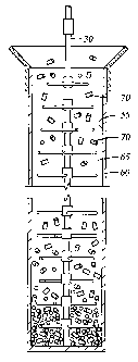
[0009] Figure 1 shows one embodiment of a damper member that is formed
horizontally relative to a filler tube.
[0010] Figure 2 shows the dampers of Figure 1 arranged along a central member.
[0011] Figure 3 is a top view of the embodiment of Figure 2 in a tube.
[0012] Figure 4 is a section view showing the tool of Figure 2 in a loading
tube being
filled with particles.
[0013] Figure 5 is a top view of another embodiment of a tool where the
dampers are
3
CA 02644976 2008-09-05
WO 2007/109442 PCT/US2007/063718
spiral-shaped.
[0014] Figure 6 is a side view showing the spiral-shaped dampers in a tube
being
filled with pellets.
[0015] Figure 7 is a top view of another embodiment of the invention wherein
the
damper members are vertically arranged and rotated relative to each other.
[0016] Figure 8 is a side view showing the embodiment of Figure 7 in a tube
being
filled with pellets.
DETAILED DESCRIPTION OF THE PREFERRED EMBODIMENT
[0017] The present invention is used with a catalyst filling process where
pellets of
catalyst are placed in a tube with the help of a loading tool. The loading
tool comprises
dampers that are formed into repeating shapes from material such as a wire or
the like in
a manner whereby at least a portion of the dampers are substantially
transverse and
axially arranged to provide substantially circumferential coverage along a
longitudinal
length of the tube. The distance between damper members can be substantially
equal or
can vary. The plurality of damper members reduces the falling velocity of the
particles
and diverts the particles from falling in straight downward paths.
[0018] In the embodiment shown in Figures 1-4, dampers 10 are arranged in a
horizontal manner along a central member 30. Each damper is symmetrically
shaped
and includes a central portion 12 and arms 15 extending outwards from each
side of the
portion 12 in a single plane that is perpendicular to the longitudinal axis of
the central
member 30. In the embodiment shown, a cross arm 20 extends at an angle of less
than
ninety degrees from an end of each arm 15. As shown in Figures 2 and 4, the
dampers
10 are arranged along the central member 30 in a manner wherein each damper is
rotationally distinct from the adjacent damper and whereby the arms 15 and
cross arms
20 extend into an annular area 65 formed between the central member 30 and an
inside
wall 55 of a tube 60. The result of the rotational differences are evident in
Figure 3.
While there is no contact between the damper 10 and the wall 55, the arms
extend
outwards far enough that pellets 70 are interrupted by the arms 15, 20 from
free falling to
4
CA 02644976 2008-09-05
WO 2007/109442 PCT/US2007/063718
the bottom of the tube 60. Depending on the job and the needs of an operator,
the arms
15 can extend outwards at a 90 degree angle from the central member and the
cross
arms 20 can likewise extend at a 90 degree angle from the arms. Figure 4
illustrates the
loading tool in use. The tool is lowered into tube the 60 in a coaxial manner
with an
annular space between the tool and an inner wall 55 of the tube. Thereafter,
pellets 70
are dropped into the tube 60 and contact various dampers as they fall towards
the
bottom of the tube. The tool can either remain stationary in the tube the
pellets approach
the bottom of the tool, at which point the tool can be periodically raised
until the tube is
full, or the tool can be gradually and continuously pulled upwards as the tube
fills. Either
of these two methods can be accomplished manually or automatically with an
appropriate mechanical device.
[0019] Figures 5 and 6 illustrate another embodiment of the loading tool 150.
As
shown, the dampers 105 making up the tool consist of a plurality of spiral or
helix-
shaped members, each of which has a slightly increased or reduced outer
diameter than
the adjacent spiral and all preferably formed of the same wire or stiffened
member.
Figure 5 is a top view showing how the spiral shapes of the dampers 105
substantially
cover the interior of a tube to stop the freefall of pellets being loaded into
the tube.
Considering Figure 6, it can be appreciated for example, that spiral 106 is
larger in
diameter than the spiral 107 thereabove but is smaller than the next lower
spiral 108. In
the embodiment shown in Figure 6, the spirals increase in diameter along a
first
longitudinal length of the tool and then decrease along a second length. In
this manner,
the loading tool has a consistent center line and the stiffened member from
which it is
formed can traverse a portion of the tube prior to forming another group of
dampers. In
each case, an annular area remains between the outer diameter of each damper
and an
inside wall 55 of the tube 60. Shaping of the damper members and changes to
length,
stiffness, number, axial spacing of the spirals along the length of the wire,
etc., can be
adapted to the material to be filled into the tube and the size of the tube.
These changes
can be accomplished since the damper is relatively inexpensive and can be
adjusted
easily. As shown in Figure 6, multiple dampers can be used along a tube's
length and
the distance between them can be varied.
5
CA 02644976 2008-09-05
WO 2007/109442 PCT/US2007/063718
[0020] In another embodiment shown in Figures 7 and 8, each damper 200 of the
loading tool is formed in the shape of a partial "Z" and each is connected in
a rotationally
fixed and distinct manner relative to dampers above and below it. Each Z shape
includes an upper horizontal leg 210, a diagonal connecting leg 215 and a
lower
horizontal leg 220. Upper and lower legs 210 and 220 are foreshortened and
connected
to a leg of the next Z at a mid point 221 such that a constant center line of
the damper is
maintained relative to the longitudinal axis of the tube 60. Due to the
unitary design, the
dampers 200 can be formed of stiff material and in a manner whereby they
remain
rotationally distinct from each other while sharing the same center line.
[0021] Figure 7 is a top view of one arrangement as it would appear in a tube
60. The
Z-shaped dampers 200 are arranged whereby they cover essentially the entire
radial
area of the inner potion of the tube (only the upper leg 200 of each Z shape
is visible). In
the embodiment of Figure 7, the dampers 200 are each rotated 30 degrees
counterclockwise from the damper thereabove and the relative angle of each
from the
horizontal is labeled. The result is a stair-stepped appearance that is
illustrated in a side
view in Figure 8 where two complete tools A, B are connected together to form
one
longer tool that extends the length of the tube 60.
[0022] In addition to the clocked arrangement of Figures 7 and 8, the shapes
can be
alternately rotated between clockwise and counterclockwise. By "clocking" the
shapes in
this manner, the pellets 70 are never permitted to fall very far in the tube
60 without
hitting a damper. In other words, the vertical distance between dampers along
any
straight vertical path in the tube is minimized by the design. For example, a
first Z could
be rotated 30 degrees clockwise from the Z thereabove. A second Z below the
first
could then be rotated 30 degrees counterclockwise from the first Z. The
arrangement
creates a loading tool wherein legs of the various Zs are more likely to
contact a falling
pellet at more equal intervals along the length of the tube 60.
[0023] Since the damper members do not occupy a substantial portion of the
cross
section of the tube at any particular axial location they can be rigid or
flexible and still
permit the particles to fall. The loading tool can be moved or jerked
primarily in both
directions axially and is pulled gradually out of the tube as the tube is
filled, or it can
6
CA 02644976 2008-09-05
WO 2007/109442 PCT/US2007/063718
remain stationary while a predetermined amount of catalyst is being added and
then
pulled upwards in the tube between catalyst filling sequences. As the loading
tool is
removed from the tube, it can be broken into sections at weakened locations
along its
length. Therefore, the amount of the loading tool that has to be handled
outside of the
tube is limited to the length between weakened portions. The particles can
pour down
into the tube through a funnel that is removed after filling is completed.
However, the
particles can be added to the tube through other methods known in the art.
While the
examples shown include "Z" shapes, it will be understood that the dampeners
could be of
a variety of shapes, which can all be substantially identical along the center
member.
For example, the shapes can be symmetrical or uniformly asymmetrical in
geometry and
can provide a balanced, limited coverage of the annulus formed between a
centerline of
the tube and a wall of the tube.
[0024] Periodic adjustments of the height of the lowest extremity of the
center member
can be made manually. This is accomplished by physically feeling the wire
member
change from tension to slackness as the lowest extremity of the center member
contacts
the catalyst interface, similar to the sensation from a weighted fishing line
contacting the
bottom of a body of water. In one embodiment of the present invention,
periodic
adjustments also can be assisted by the addition of a sensor member at the
lowest
extremity of the center member. This sensor member can communicate with the
top of
the center member to provide visual or auditory indication of contact with the
catalyst
interface.
[0025] With embodiments of the present invention, a novel, reproducible, and
quick
filling method is disclosed. The method is gentle to the particles such that
crushing of
particles during the filling operation is avoided. An even filling of the tube
is also
obtained, and thus one result has been avoidance of uneven temperature
distribution
when a tube filled with catalyst is in operation. Further, an even density of
particles in
the tubes is attained without exposing them to tapping/vibration, which is
both time-
consuming and damaging to the tubes. Consequently, time is saved both during
filling
and also since the tubes do not have to be tapped. The method is simple, cost
efficient,
and can be modified both quickly and easily. Additionally, it is to only a
very small
7
CA 02644976 2008-09-05
WO 2007/109442 PCT/US2007/063718
degree dependent upon whoever is the particular operator during the filling
process.
Furthermore, errors connected with filling of particles into socks are
avoided. A
substantial degree of freedom regarding packaging and the form of transport
for the
particles also is obtained.
[0026] While the foregoing is directed to embodiments of the present
invention, other
and further embodiments of the invention may be devised without departing from
the
basic scope thereof, and the scope thereof is determined by the claims that
follow.
8