Sélection de la langue

Search

Sommaire du brevet 2645261 

Énoncé de désistement de responsabilité concernant l'information provenant de tiers

Une partie des informations de ce site Web a été fournie par des sources externes. Le gouvernement du Canada n'assume aucune responsabilité concernant la précision, l'actualité ou la fiabilité des informations fournies par les sources externes. Les utilisateurs qui désirent employer cette information devraient consulter directement la source des informations. Le contenu fourni par les sources externes n'est pas assujetti aux exigences sur les langues officielles, la protection des renseignements personnels et l'accessibilité.

Disponibilité de l'Abrégé et des Revendications

L'apparition de différences dans le texte et l'image des Revendications et de l'Abrégé dépend du moment auquel le document est publié. Les textes des Revendications et de l'Abrégé sont affichés :

  • lorsque la demande peut être examinée par le public;
  • lorsque le brevet est émis (délivrance).
(12) Demande de brevet: (11) CA 2645261
(54) Titre français: CHARIOT DE TRANSPORT DE BATI CHARGE
(54) Titre anglais: TROLLEY FOR CARRYING LOADED RACK
Statut: Réputée abandonnée et au-delà du délai pour le rétablissement - en attente de la réponse à l’avis de communication rejetée
Données bibliographiques
(51) Classification internationale des brevets (CIB):
  • B65G 7/04 (2006.01)
  • B60B 33/04 (2006.01)
  • B62B 3/06 (2006.01)
  • B66F 5/00 (2006.01)
(72) Inventeurs :
  • FOOTE, MEGAN (Canada)
  • SUMNERS, LAUGHLIN (Canada)
(73) Titulaires :
  • MEGAN FOOTE
  • LAUGHLIN SUMNERS
(71) Demandeurs :
  • MEGAN FOOTE (Canada)
  • LAUGHLIN SUMNERS (Canada)
(74) Agent:
(74) Co-agent:
(45) Délivré:
(22) Date de dépôt: 2008-11-26
(41) Mise à la disponibilité du public: 2010-05-26
Licence disponible: S.O.
Cédé au domaine public: S.O.
(25) Langue des documents déposés: Anglais

Traité de coopération en matière de brevets (PCT): Non

(30) Données de priorité de la demande: S.O.

Abrégés

Désolé, les abrégés concernant le document de brevet no 2645261 sont introuvables.

Revendications

Note : Les revendications sont présentées dans la langue officielle dans laquelle elles ont été soumises.


We claim:
1. A trolley for transporting a rack having a pair of spaced uprights each
resting on a hor-
izontally extending shoe, each said shoe spaced apart from a floor by a foot,
said trolley in-
cluding: (i) a shoe-supporting component having a forward portion adapted to
extend beneath
said shoe and a rear portion; (ii) a first caster associated with said rear
portion and movable
vertically for selective raising and lowering of said first caster with
resulting raising and lowering
of said rear portion; and (iii) an auxiliary component having clamping means
for selectively
clamping said auxiliary component to said forward portion, said auxiliary
component further
having a second caster which is movable vertically for selectively raising and
lowering of said
second caster with resulting raising and lowering of said forward portion when
clamped to said
auxiliary component.
2. A trolley for transporting a rack having a pair of spaced uprights each
resting on a hor-
izontally extending shoe, each said shoe extending horizontally from opposite
sides of a base of a
separate said upright and being spaced apart from a floor by at least two
feet, said trolley in-
cluding: (i) a shoe-supporting component having a forward portion adapted to
extend beneath
said shoe and a rear portion; (ii) a first caster associated with said rear
portion which is movable
vertically for selective raising and lowering of said first caster with
resulting raising and lowering
of said rear portion; and (iii) an auxiliary component having clamping means
for selectively
clamping said auxiliary component to said forward portion, said auxiliary
component further
6

having a second caster which is movable vertically for selectively raising and
lowering of said
second caster with resulting raising and lowering of said forward portion when
clamped to said
auxiliary component.
3. A trolley for transporting a rack having a pair of spaced uprights each
resting on a hor-
izontally extending shoe, each said shoe extending horizontally from opposite
sides of a base of a
separate said upright and being spaced apart from a floor by at least two
feet, said trolley in-
cluding: (i) a shoe-supporting component having a forward portion adapted to
extend beneath
said shoe and a rear portion; (ii) a pair of spaced apart first casters
associated with said rear
portion and each which is movable vertically for selective raising and
lowering of said first
casters with resulting raising and lowering of said rear portion; and (iii) a
pair of auxiliary
component s each having clamping means for selectively clamping said auxiliary
component s to
said forward portion, said auxiliary components further having second casters
which are movable
vertically for selectively raising and lowering of said second casters with
resulting raising and
lowering of said forward portion when clamped to said auxiliary components.
4. The trolley of claims 1,2 or 3 wherein said clamping means includes a pair
of plates
separated by a space within which said outer portion is removably
accommodated, said plates
being movable from a closed position in which said forward portion is clamped
to said auxiliary
component to an open position in which said forward portion is free to be
moved and out of said
space.
7

Description

Note : Les descriptions sont présentées dans la langue officielle dans laquelle elles ont été soumises.

CA 02645261 2008-11-26
This invention relates to trolleys for carrying loads and more particularly to
a trolley that
comes apart for mounting beneath a loaded rack and assembles to form a
conveyance for trans-
porting the rack while it is loaded from one location to another.
Racks for holding or storing items can be extremely heavy when fully loaded.
They are
usually quite safe as long as they are not moved but if they are moved, they
become unstable and
susceptible to toppling over. If they do topple over, the items on the rack
are usually damaged or
soiled and the racks themselves are damaged beyond repair. Moreover, because
the racks are so
unstable when they are being moved, they may suddenly, without warning, fall
and cause injury
or even death to a person in the path of the falling rack.
To avoid the risk of a rack toppling over during transportation, a rack is
usually unloaded
before it is moved. Unloading and then reloading a fully loaded rack is very
time consuming. As
well, items on the rack may be mixed up at this time and further time must be
spent in checking
the items as they are being placed back on the rack to ensure that the items
are in their rightful
place.
We have invented a trolley that is designed to carry a heavily loaded rack.
There is no
necessity to move any of the items on the rack before the trolley is attached
or while the rack is
moved on the trolley. As well, there is no possibility that any of the items
on the rack may be
mixed up as a result of the move since the items are not moved from the rack
during the move.
Briefly, the trolley of our invention includes a shoe-supporting component
having a rear
portion and a forward portion adapted to extend beneath the shoe of a rack. A
caster is
1

CA 02645261 2008-11-26
attached to the rear portion and is movable vertically for selectively raising
and lowering the
caster with resulting raising and lowering of the rear portion. The trolley
also includes an
auxiliary component having a clamp for selectively clamping the auxiliary
component to the
forward portion. The auxiliary component further has a second caster which is
movable vertically
for selectively raising and lowering of the second caster with resulting
raising and lowering of the
forward portion of the shoe-supporting component when clamped to the auxiliary
component.
The trolley of the invention is described with reference to the accompanying
drawings in
which:
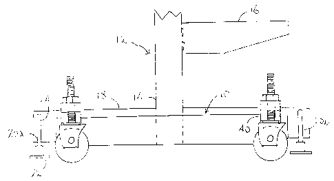
Figure 1 is a front elevation of a shoe-supporting component of the trolley in
conjunction
with the lower portion of a conventional rack for storing or holding objects;
Figure 2 is a side elevation of the shoe-supporting component and an auxiliary
component of the trolley;
Figure 3 is a plan view of both the shoe-supporting component and the
auxiliary
component of the trolley;
Figure 4 is an elevation of the shoe-supporting component in the process of
being placed
beneath the shoe of a rack; and
Figure 5 is an elevation of the shoe-supporting component in the process of
being
attached to the auxiliary component of the trolley.
Like reference characters refer to like parts throughout the description of
the drawings.
2

CA 02645261 2008-11-26
With reference to Figure 1, the shoe-supporting component of the trolley,
generally 10, is
shown attached to the lower portion of a conventional rack generally 12. The
rack is composed of
a pair of spaced apart uprights 14, one of which being illustrated, to which a
number of shelves
16 are removably attached. The lower ends of each upright is attached to a
shoe 18 which extends
horizontally outward from opposite sides of the upright. Feet 20a,b are
threadably attached to the
shoe adjacent to each of its ends.
Each foot has a plate 22 which contacts a floor unless the rack is raised by
the trolley of
the invention in the manner described below. Extending upward from the plate
is a threaded rod
24 which is attached to the shoe. When the plate is rotated, the level of the
shoe either rises
above a floor or descends toward the floor.
With reference to Figures 1 and 2, the shoe-supporting component has an
angular mem-
ber, generally 26 having a forward horizontal plate 30 and a rear vertical
plate 32. Attached to
opposite ends of the angular component is a housing 34. A threaded vertically
extending rod 36
is threadably attached to each housing. A caster 38 is attached to the lower
end of each rod and is
free to rotate and to swivel. A hexagonal nut 40 contacts the upper wall of
each housing and is
threadably attached to the rod. Rotation of the nut causes the caster to rise
and fall relative to the
housing.
As illustrated in Figure 1, two housings 40 are attached to the angular
component at each
of its ends. The angular component is slightly shorter than the distance
between feet 20a,b so that
3

CA 02645261 2008-11-26
housings 40 are adjacent to the two feet when connected to the shoe as
described below.
With reference to Figures 2 and 2, an auxiliary component, generally 50, has a
pair of
spaced apart horizontal plates 52a,b attached to a vertical member 54. A bolt
56 passes through a
threaded opening in the upper plate 52a, through a threaded opening 58 in the
horizontal plate 30
and into contact with the upper face of the lower plate 52b. Tightening of the
bolt causes
horizontal plate 30 to rise into contact with the lower face of the upper
plate 52a with resulting
clamping of the shoe-supporting component to the auxiliary component.
Loosening of the bolt
causes the bolt to rise out of opening in the horizontal plate so that the
shoe-supporting and
auxiliary components can be separated from one another.
A housing 60 of the same construction as housing 34 is attached to vertical
member 54.
A threaded vertical rod 62 is threadably attached to the housing and, like rod
36, a caster 64 is
attached to its lower end while a hexagonal nut 66 serves to adjust the
elevation of caster 64
relative to housing 60.
The operation of the trolley is described with reference to Figures 3-5. With
reference
first to Figure 4, the trolley is attached to the rack by first inserting the
horizontal component 30
of the shoe-supporting component into the space between shoe 18 and a floor 70
at one end of
the rack. Two auxiliary components 50 are then positioned adjacent to housings
34 of the shoe-
supporting components as illustrated in Figures 3 and 5 so that plates 52a,b
are adjacent to the
forward edge 30a of the horizontal component of the angular member.
4

CA 02645261 2008-11-26
The next step in the attachment of the trolley to the rack is to raise the
forward edge 30 of
the horizontal component to the level of the space 72 between the two plates
52a,b. That step can
be accomplished using a crowbar. The auxiliary component is then advanced
toward the shoe-
supporting component in the direction of arow 74 in order to move the forward
edge 30a into
space 72. Bolt 56 is then tightened to clamp the two components together.
Hexagonal nuts 40, 66 are then turned to lower castors 38, 64, respectively,
until they
contact the floor. They are further tighten to raise feet 20 of the rack off
the floor as illustrated in
Figure 1.
The process is then repeated at the other end of the rack in order to raise
the feet at that
end off the floor. The rack is then wholly supported by two trolleys, one at
each at each end of
the rack. The rack is then ready to be transported to a new location.
It will be understood, of course, that modifications can be made in the
structure of the
trolley of the invention without departing from the scope of the invention as
defined in the
appended claims.

Dessin représentatif
Une figure unique qui représente un dessin illustrant l'invention.
États administratifs

2024-08-01 : Dans le cadre de la transition vers les Brevets de nouvelle génération (BNG), la base de données sur les brevets canadiens (BDBC) contient désormais un Historique d'événement plus détaillé, qui reproduit le Journal des événements de notre nouvelle solution interne.

Veuillez noter que les événements débutant par « Inactive : » se réfèrent à des événements qui ne sont plus utilisés dans notre nouvelle solution interne.

Pour une meilleure compréhension de l'état de la demande ou brevet qui figure sur cette page, la rubrique Mise en garde , et les descriptions de Brevet , Historique d'événement , Taxes périodiques et Historique des paiements devraient être consultées.

Historique d'événement

Description Date
Exigences relatives à la révocation de la nomination d'un agent - jugée conforme 2020-09-01
Requête d'examen reçue 2013-11-27
Le délai pour l'annulation est expiré 2011-11-28
Demande non rétablie avant l'échéance 2011-11-28
Réputée abandonnée - omission de répondre à un avis exigeant une traduction 2011-05-25
Inactive : Incomplète 2011-02-25
Réputée abandonnée - omission de répondre à un avis sur les taxes pour le maintien en état 2010-11-26
Demande publiée (accessible au public) 2010-05-26
Inactive : Page couverture publiée 2010-05-25
Inactive : CIB en 1re position 2009-08-28
Inactive : CIB attribuée 2009-08-28
Exigences de rétablissement - réputé conforme pour tous les motifs d'abandon 2008-12-30
Exigences de dépôt - jugé conforme 2008-12-23
Inactive : Certificat de dépôt - Sans RE (Anglais) 2008-12-23
Demande reçue - nationale ordinaire 2008-12-23
Déclaration du statut de petite entité jugée conforme 2008-11-26

Historique d'abandonnement

Date d'abandonnement Raison Date de rétablissement
2011-05-25
2010-11-26

Historique des taxes

Type de taxes Anniversaire Échéance Date payée
Taxe pour le dépôt - petite 2008-11-26
Titulaires au dossier

Les titulaires actuels et antérieures au dossier sont affichés en ordre alphabétique.

Titulaires actuels au dossier
MEGAN FOOTE
LAUGHLIN SUMNERS
Titulaires antérieures au dossier
S.O.
Les propriétaires antérieurs qui ne figurent pas dans la liste des « Propriétaires au dossier » apparaîtront dans d'autres documents au dossier.
Documents

Pour visionner les fichiers sélectionnés, entrer le code reCAPTCHA :


Pour visualiser une image, cliquer sur un lien dans la colonne description du document. Pour télécharger l'image (les images), cliquer l'une ou plusieurs cases à cocher dans la première colonne et ensuite cliquer sur le bouton "Télécharger sélection en format PDF (archive Zip)" ou le bouton "Télécharger sélection (en un fichier PDF fusionné)".

Liste des documents de brevet publiés et non publiés sur la BDBC .

Si vous avez des difficultés à accéder au contenu, veuillez communiquer avec le Centre de services à la clientèle au 1-866-997-1936, ou envoyer un courriel au Centre de service à la clientèle de l'OPIC.


Description du
Document 
Date
(aaaa-mm-jj) 
Nombre de pages   Taille de l'image (Ko) 
Abrégé 2010-05-26 1 3
Description 2008-11-26 5 172
Revendications 2008-11-26 2 77
Dessins 2008-11-26 3 35
Dessin représentatif 2010-04-28 1 6
Page couverture 2010-05-13 1 24
Description 2011-12-28 5 172
Revendications 2011-12-28 2 77
Certificat de dépôt (anglais) 2008-12-23 1 157
Rappel de taxe de maintien due 2010-07-27 1 114
Courtoisie - Lettre d'abandon (taxe de maintien en état) 2011-01-21 1 172
Courtoisie - Lettre d'abandon (incompléte) 2011-07-20 1 164
Correspondance 2008-12-29 1 16
Correspondance 2011-02-25 1 27