Sélection de la langue

Search

Sommaire du brevet 2646851 

Énoncé de désistement de responsabilité concernant l'information provenant de tiers

Une partie des informations de ce site Web a été fournie par des sources externes. Le gouvernement du Canada n'assume aucune responsabilité concernant la précision, l'actualité ou la fiabilité des informations fournies par les sources externes. Les utilisateurs qui désirent employer cette information devraient consulter directement la source des informations. Le contenu fourni par les sources externes n'est pas assujetti aux exigences sur les langues officielles, la protection des renseignements personnels et l'accessibilité.

Disponibilité de l'Abrégé et des Revendications

L'apparition de différences dans le texte et l'image des Revendications et de l'Abrégé dépend du moment auquel le document est publié. Les textes des Revendications et de l'Abrégé sont affichés :

  • lorsque la demande peut être examinée par le public;
  • lorsque le brevet est émis (délivrance).
(12) Brevet: (11) CA 2646851
(54) Titre français: PALAN POUR INSTALLATION D'ATTELAGE
(54) Titre anglais: HITCH INSTALLATION HOIST
Statut: Accordé et délivré
Données bibliographiques
(51) Classification internationale des brevets (CIB):
  • B66C 23/48 (2006.01)
  • B60D 01/36 (2006.01)
  • B62D 53/08 (2006.01)
  • B66C 01/10 (2006.01)
  • B66C 01/66 (2006.01)
  • B66C 23/18 (2006.01)
(72) Inventeurs :
  • SHARP, GENE (Etats-Unis d'Amérique)
(73) Titulaires :
  • U-HAUL INTERNATIONAL, INC.
(71) Demandeurs :
  • U-HAUL INTERNATIONAL, INC. (Etats-Unis d'Amérique)
(74) Agent: MBM INTELLECTUAL PROPERTY AGENCY
(74) Co-agent:
(45) Délivré: 2016-02-09
(22) Date de dépôt: 2008-12-17
(41) Mise à la disponibilité du public: 2009-07-25
Requête d'examen: 2013-11-27
Licence disponible: S.O.
Cédé au domaine public: S.O.
(25) Langue des documents déposés: Anglais

Traité de coopération en matière de brevets (PCT): Non

(30) Données de priorité de la demande:
Numéro de la demande Pays / territoire Date
12/020,493 (Etats-Unis d'Amérique) 2008-01-25

Abrégés

Abrégé français

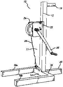
Un mécanisme de treuil portable est présenté pour soulever une installation d'attelage sous une plateforme de véhicule. L'attelage comporte un trou de boule d'attelage et la plateforme de véhicule comporte un trou à aligner avec la boule d'attelage lorsque l'attelage est installé. Le mécanisme de treuil comprend un cadre de treuil et un enrouleur servant à déployer et tirer un câble. L'enrouleur est soutenu par le cadre au-dessus du trou dans la plateforme du véhicule. L'élément allongé est attaché au câble. L'élément allongé peut être orienté dans une première position où il peut passer dans le trou de la plateforme du véhicule et le trou de boule d'attelage. Également, l'élément allongé peut être orienté dans une deuxième position où il ne peut pas traverser le trou de boule d'attelage. L'élément allongé peut être descendu dans le trou de la plateforme du véhicule et le trou de boule d'attelage dans la première orientation et peut fixer le câble au treuil dans la deuxième orientation.


Abrégé anglais

A portable hoist assembly is provided for lifting a hitch to be installed on the underside of a vehicle platform. The hitch has a hitch ball hole and the vehicle platform has a hole to be aligned with the hitch ball hole when the hitch is installed. The hoist assembly includes a hoist frame and a winch for paying out and drawing in a cable. The winch is supported by the frame above the vehicle platform hole. An elongated member is attached to the cable. The elongated member can be oriented in a first position wherein it can pass through the vehicle platform hole and the hitch ball hole. Also, the elongated member can be oriented in a second position wherein it cannot pass through the hitch ball hole. The elongated member can be lowered through the vehicle platform hole and the hitch ball hole in the first orientation and can secure the cable to the hitch in the second orientation.

Revendications

Note : Les revendications sont présentées dans la langue officielle dans laquelle elles ont été soumises.


What is claimed is:
1. A portable hoist assembly for lifting a hitch to be installed on the
underside of a vehicle
platform, wherein the hitch has a hitch ball hole and the vehicle platform has
a hole to be aligned
with the hitch ball hole when the hitch is installed, the hoist assembly
comprising:
a hoist frame;
a winch for paying out and drawing in a cable having an end for securing to
the hitch,
wherein the winch is supported by the frame above the vehicle platform hole;
an elongated member attached to the cable end such that the elongated member
can be
oriented in:
a first position wherein the elongated member can pass through the vehicle
platform hole and the hitch ball hole; and
a second position wherein the elongated member cannot pass through the hitch
ball hole;
whereby the elongated member can be lowered through the vehicle platform hole
and the
hitch ball hole in the first orientation and can secure the cable to the hitch
in the second
orientation.
2. The portable hoist assembly of claim 1 wherein the winch comprises a
friction-clutch
type winch.
3. The portable hoist assembly of claim 1 wherein the winch comprises a
ratcheting pawl.
4. The portable hoist assembly of claim 1 wherein the elongated member
comprises a tube.
5. The portable hoist assembly of claim 4 wherein the tube has a length less
than the
diameter of the hitch ball hole and elongated member further comprises a pin
that can be
positioned within the tube and that has a length greater than the diameter of
the hitch ball hole.
6. The portable hoist assembly of claim 1 wherein the elongated member
comprises a pin.
7. The portable hoist assembly of claim 1 wherein the elongated member has a
length
greater than the diameter of the hitch ball hole.
8. A method for installing a trailer tow hitch on the underside of a vehicle
platform, wherein
6

the hitch has a hitch ball hole and the vehicle platform has a hole to be
aligned with the hitch ball
hole when the hitch is installed, the method comprising:
providing a winch for paying out and drawing in a cable having an end for
securing to the
hitch, wherein an elongated member attached to the cable end such that the
elongated member
can be oriented in:
a first orientation wherein the elongated member can pass through the vehicle
platform hole and the hitch ball hole; and
a second orientation wherein the elongated member cannot pass through the
hitch
ball hole;
supporting the winch above the vehicle platform hole;
lowering the elongated member through the vehicle platform hole and the
hitchball hole
in the first orientation; and
securing the elongated member the hitch by placing elongated member in the
second
orientation after it is lowered through the hitch ball hole.
9. A method of claim 8 further comprising lifting the hitch into position for
installation to
the underside of the vehicle platform.
10. The method of claim 8 wherein the winch comprises a friction-clutch type
winch.
11. The method of claim 8 wherein the winch comprises a ratcheting pawl.
12. The method of claim 8 wherein the elongated member comprises a tube.
13. The method of claim 12 wherein the tube has a length less than the
diameter of the hitch
ball hole and elongated member further comprises a pin that can be positioned
within the tube
and that has a length greater than the diameter of the hitch ball hole.
14. The method of claim 8 wherein the elongated member comprises a pin.
15. The method of claim 8 wherein the elongated member has a length greater
than the
diameter of the hitch ball hole.
16. A portable hoist assembly for lifting a hitch to be installed on the
underside of a vehicle
platform, wherein the hitch has a hitch ball hole and the vehicle platform has
a hole to be aligned
7

with the hitch ball hole when the hitch is installed, the hoist assembly
comprising:
a hoist frame positioned on the vehicle platform;
a winch adapted to pay out and draw in a cable wherein the winch is supported
by the
frame above the vehicle platform hole; and
an elongated member attached to the cable wherein the elongated member can be
oriented in:
a first orientation for passing through the vehicle platform hole and the
hitch ball
hole; and
a second orientation wherein the elongated member cannot pass through the
hitch
ball hole;
whereby the elongated member can be lowered through the vehicle platform hole
and the
hitch ball hole in the first orientation and can secure the cable to the hitch
in the second
orientation.
17. The portable hoist assembly of claim 16 wherein the elongated member
comprises a tube.
18. The portable hoist assembly of claim 17 wherein the tube has a length less
than the
diameter of the hitch ball hole and elongated member further comprises a pin
that can be
positioned within the tube and that has a length greater than the diameter of
the hitch ball hole.
19. The portable hoist assembly of claim 16 wherein the elongated member
comprises a pin.
20. The portable hoist assembly of claim 16 wherein the elongated member has a
length
greater than the diameter of the hitch ball hole.
8

Description

Note : Les descriptions sont présentées dans la langue officielle dans laquelle elles ont été soumises.


CA 02646851 2008-12-17
Hitch Installation Hoist
BACKGROUND
[00011
The present invention relates generally to hoists. More particularly, it
relates to a hoist employed to aid in lifting, positioning and holding a
trailer tow hitch beneath a
vehicle to facilitate installation of the hitch.
[0002]
Typically, a trailer hitch assembly mounted on the cargo bed of a vehicle
is used to secure a large trailer, such as a gooseneck trailer. Trailer hitch
assemblies for use with
the cargo bed of a vehicle present inherent problems in installing the hitch
assembly. Typically,
such hitch assemblies are installed beneath the cargo bed of the vehicle. The
weight of the trailer
requires the hitch assembly to be of substantial construction. In positioning
the hitch beneath a
motor vehicle it is necessary to both lift the hitch and tilt the hitch.
Because the hitch can be
quite heavy, the person installing the hitch usually requires mechanical
assistance or the
assistance of another person in effecting the different movements required of
the hitch.
[0003]
Previously, hitch hoists have been used for positioning and holding hitches
beneath a motor vehicle. Such hoists, however, are relatively complex and
expensive. There
continues to be a need, therefore, for a hitch hoist that is simple, that is
inexpensive in
construction, that can be employed by a single person to install a hitch with
minimum exertion of
effort and that is reliable in operation. It is an object of the present
invention to provide such a
hoist for installing a hitch beneath the bed of a motor vehicle.
[0004]
Additional objects and advantages of the invention will be set forth in the
description that follows, and in part will be apparent from the description,
or may be learned by
practice of the invention. The objects and advantages of the invention may be
realized and
obtained by means of the instrumentalities and combinations pointed out in the
appended claims.
SUMMARY OF THE INVENTION
100051
To achieve the foregoing objects, and in accordance with the purposes of
the invention as embodied and broadly described in this document, there is
provided a portable
hoist assembly for lifting a hitch to be installed on the underside of a
vehicle bed, wherein the
hitch has a hitch ball hole and the vehicle bed has a hole to be aligned with
the hitch ball hole
when the hitch is installed. The hoist assembly includes a hoist frame and a
winch for paying out
and drawing in a cable having an end for securing to the hitch. The winch is
supported by the

CA 02646851 2008-12-17
=
frame above the vehicle bed hole. A rigid elongated member is attached to the
cable end. The
elongated member can be oriented in a first position wherein it can pass
through the vehicle bed
hole and the hitch ball hole. Also, the elongated member can be oriented in a
second position
wherein it cannot pass through the hitch ball hole. In this configuration, the
elongated member
can be lowered through the vehicle bed hole and the hitch ball hole in the
first orientation and
can secure the cable to the hitch in the second orientation.
[00061 In one suitable embodiment, the elongated member can be in
the form of a
rigid tube or pin. The elongated member has a length greater than the diameter
of the hitch ball
hole. In a preferred embodiment, the elongated member includes a rigid tube
that has a length
less than the diameter of the hitch ball hole and a pin that can be positioned
within the tube and
that has a length greater than the diameter of the hitch ball hole.
[0007] To install a hitch assembly, the hoist is positioned in the
vehicle bed such
that the winch is supported above the vehicle platform hole. The elongated
member is lowered
through the vehicle platform hole and the hitch ball hole in the first
orientation. The elongated
member is then secured to the hitch by placing it in the second orientation
after it is lowered
through the hitch ball hole. The hitch is then lifted into position for
installation to the underside
of the vehicle bed.
BRIEF DESCRIPTION OF THE DRAWINGS
[0008] The accompanying drawings, which are incorporated in and
constitute a
part of the specification, illustrate the presently preferred embodiments of
the invention, and
together with the general description given above and the detailed description
of the preferred
methods and embodiments given below, serve to explain the principles of the
invention.
[0009] FIG. 1 is a front-right perspective view showing a hoist
according to the
present invention;
[0010] FIG. 2 is a rear-right perspective view of the hoist of FIG.
1;
[0011] FIG. 3 is a right side perspective view of the hoist of FIG.
1;
100121 FIG. 4 is a side view of a vehicle in partial cross section
showing the hoist
of FIG. 1 positioned in the bed of the vehicle and holding a hitch in place
below the bed for
installation; and
2

CA 02646851 2008-12-17
10013) FIG. 5 is a perspective view in partial cross-section
showing the hoist of
FIG. 1 positioned in the bed of the vehicle of FIG. 4 and holding the trailer
hitch in place below
the bed for installation.
DETAILED DESCRIPTION
100141 Reference will now be made in more detail to presently
preferred methods
and embodiments of the invention, as illustrated in the accompanying drawings.
While the
invention is described more fully with reference to these examples and
drawings, the invention in
its broader aspects is not limited to the specific details, representative
devices, and illustrative
examples shown and described. Rather, the description which follows is to be
understood as a
broad, teaching disclosure directed to persons of ordinary skill in the
appropriate arts, and not as
limiting upon the invention.
100151 In the drawings, the reference numeral 10 designates
generally a hitch
hoist in accordance with the invention. The hoist 10 includes a frame 11 that
includes an upright
member 12 mounted to a platform 14. The platform 14 is fabricated from two
longitudinal
tubular members 16a, 16b, a transverse tubular member 18 and an opposing
longitudinal member
20. The longitudinal members 16a, 16b are connected to the transverse member
18 and extend
perpendicularly to one side of the upright member 12. The opposing
longitudinal member 20
also is connected to the transverse member 18 and extends perpendicularly to
an opposing side
of the upright member 12. The hoist 10 is provided with a hand grip 19 near
the top of the
upright member 12 for lifting and positioning the hoist 10. A handle 21 is
mounted near the
midpoint of the upright member 12 for carrying the hoist 10.
[00161 In a presently preferred embodiment, the upright member 12,
the
longitudinal members 16a, 16b, the transverse member 18 and the opposing
longitudinal member
20 are fabricated from tubular stock, which preferably has a non-circular
cross-sectional shape,
such as a rectangle or square. A preferred material for the stock is steel.
Upon reading this
disclosure, however, those of skill in the art will recognize that the tubular
stock my be
fabricated from other suitable material, such as aluminum or other suitable
metals. The upright
member 12, longitudinal members 16a, 16b, transverse member 18 and opposing
longitudinal
member 20 are welded together to form the frame 11.
[00171 A winch plate 22 is affixed to the front face of the upright
member 12 for
mounting a winch 24 to the frame 11. The winch 24 is bolted or otherwise
affixed to the winch
3

CA 02646851 2008-12-17
plate 22. The winch 24 is operated by a hand crank 26 and can be operated in
both a forward and
reverse direction to reel in or pay out a length of cable 28. In one exemplary
embodiment, the
winch 24 can be equipped with a friction clutch (not shown) to hold the winch
drum in selected
positions to which it is turned. In another embodiment, the winch 24 can be a
ratcheting pawl
winch. In either case, the winch can be operated in both forward and reverse
directions.
[00181 A rigid elongated member 23 is attached to the end of the
cable 28. The
elongated member has a length greater than the diameter of the hitch ball hole
38 discussed
below. In a preferred embodiment, the elongated member 23 can be in the form
of a rigid tube
or pin. In another preferred embodiment, the elongated member 23 includes a
rigid tube that has
a length less than the diameter of the hitch ball hole 38 and a pin that can
be slidably positioned
within the tube and that has a length greater than the diameter of the hitch
ball hole 38. The
elongated member is fabricated from a material sufficient to hold the weight
of a hitch, such as
steel.
[00191 Referring to FIGs. 4 and 5, in operation the winch 24 is
used to raise and
lower a hitch 30 to be mounted beneath a cargo bed 42 of a vehicle 40, such as
a pick-up truck.
Such a hitch is commonly known as a "gooseneck" trailer hitch and typically
includes side
mounting brackets 32a, 32b that attach to the vehicle frame 44, cross members
34 joining the
mounting brackets 32a, 32b, and a center portion 36 that attaches to the cross
members 34 and
provides means for mounting a hitch ball (not shown) including a hitch ball
hole 38. Installation
of the hitch 30 requires that a hole be cut in the vehicle bed 42 so that the
hitch ball is accessible
from above.
[00201 To install the hitch 30, the hoist 10 is placed in the
vehicle bed 42 so that
the winch 24 is just above the hole cut in the floor of the vehicle bed for
accommodating the
hitch ball. In a generally vertical orientation, the elongated member 23 can
be lowered through
the hole in the vehicle bed 42, through the hitch ball hole 38 in the hitch
30. The elongated
member 23 is then secured to the hitch by placing it in a generally horizontal
orientation after it
is lowered through the hitch ball hole. The hitch 30 is then lifted into
position for installation to
the underside of the vehicle bed.
[00211 From the foregoing it should be apparent that this
invention provides a
hoist which enables one person to lift a trailer hitch into position beneath
the undercarriage of a
motor vehicle and to hold the hitch in that position while mounting holes are
marked or drilled
4

CA 02646851 2015-07-03
and while fasteners are installed. The versatility of the hoist permits its
use for a variety of types
and styles of hitches and a variety of motor vehicles.

Dessin représentatif
Une figure unique qui représente un dessin illustrant l'invention.
États administratifs

2024-08-01 : Dans le cadre de la transition vers les Brevets de nouvelle génération (BNG), la base de données sur les brevets canadiens (BDBC) contient désormais un Historique d'événement plus détaillé, qui reproduit le Journal des événements de notre nouvelle solution interne.

Veuillez noter que les événements débutant par « Inactive : » se réfèrent à des événements qui ne sont plus utilisés dans notre nouvelle solution interne.

Pour une meilleure compréhension de l'état de la demande ou brevet qui figure sur cette page, la rubrique Mise en garde , et les descriptions de Brevet , Historique d'événement , Taxes périodiques et Historique des paiements devraient être consultées.

Historique d'événement

Description Date
Représentant commun nommé 2019-10-30
Accordé par délivrance 2016-02-09
Inactive : Page couverture publiée 2016-02-08
Inactive : Taxe finale reçue 2015-11-13
Préoctroi 2015-11-13
Lettre envoyée 2015-11-02
Un avis d'acceptation est envoyé 2015-11-02
Inactive : Approuvée aux fins d'acceptation (AFA) 2015-10-26
Inactive : QS réussi 2015-10-26
Modification reçue - modification volontaire 2015-07-03
Inactive : Dem. de l'examinateur par.30(2) Règles 2015-03-06
Inactive : Rapport - Aucun CQ 2015-02-25
Lettre envoyée 2013-12-02
Exigences pour une requête d'examen - jugée conforme 2013-11-27
Requête d'examen reçue 2013-11-27
Toutes les exigences pour l'examen - jugée conforme 2013-11-27
Demande publiée (accessible au public) 2009-07-25
Inactive : Page couverture publiée 2009-07-24
Inactive : CIB attribuée 2009-06-26
Inactive : CIB en 1re position 2009-06-26
Inactive : CIB attribuée 2009-06-26
Inactive : Lettre officielle 2009-01-20
Inactive : Certificat de dépôt - Sans RE (Anglais) 2009-01-19
Lettre envoyée 2009-01-19
Demande reçue - nationale ordinaire 2009-01-19

Historique d'abandonnement

Il n'y a pas d'historique d'abandonnement

Taxes périodiques

Le dernier paiement a été reçu le 2015-12-03

Avis : Si le paiement en totalité n'a pas été reçu au plus tard à la date indiquée, une taxe supplémentaire peut être imposée, soit une des taxes suivantes :

  • taxe de rétablissement ;
  • taxe pour paiement en souffrance ; ou
  • taxe additionnelle pour le renversement d'une péremption réputée.

Les taxes sur les brevets sont ajustées au 1er janvier de chaque année. Les montants ci-dessus sont les montants actuels s'ils sont reçus au plus tard le 31 décembre de l'année en cours.
Veuillez vous référer à la page web des taxes sur les brevets de l'OPIC pour voir tous les montants actuels des taxes.

Titulaires au dossier

Les titulaires actuels et antérieures au dossier sont affichés en ordre alphabétique.

Titulaires actuels au dossier
U-HAUL INTERNATIONAL, INC.
Titulaires antérieures au dossier
GENE SHARP
Les propriétaires antérieurs qui ne figurent pas dans la liste des « Propriétaires au dossier » apparaîtront dans d'autres documents au dossier.
Documents

Pour visionner les fichiers sélectionnés, entrer le code reCAPTCHA :


Pour visualiser une image, cliquer sur un lien dans la colonne description du document. Pour télécharger l'image (les images), cliquer l'une ou plusieurs cases à cocher dans la première colonne et ensuite cliquer sur le bouton "Télécharger sélection en format PDF (archive Zip)" ou le bouton "Télécharger sélection (en un fichier PDF fusionné)".

Liste des documents de brevet publiés et non publiés sur la BDBC .

Si vous avez des difficultés à accéder au contenu, veuillez communiquer avec le Centre de services à la clientèle au 1-866-997-1936, ou envoyer un courriel au Centre de service à la clientèle de l'OPIC.


Description du
Document 
Date
(aaaa-mm-jj) 
Nombre de pages   Taille de l'image (Ko) 
Description 2008-12-16 5 253
Abrégé 2008-12-16 1 22
Revendications 2008-12-16 3 121
Dessins 2008-12-16 5 80
Dessin représentatif 2009-06-28 1 8
Description 2015-07-02 5 243
Courtoisie - Certificat d'enregistrement (document(s) connexe(s)) 2009-01-18 1 103
Certificat de dépôt (anglais) 2009-01-18 1 157
Rappel de taxe de maintien due 2010-08-17 1 115
Rappel - requête d'examen 2013-08-19 1 117
Accusé de réception de la requête d'examen 2013-12-01 1 176
Avis du commissaire - Demande jugée acceptable 2015-11-01 1 161
Correspondance 2009-01-18 1 14
Modification / réponse à un rapport 2015-07-02 4 92
Taxe finale 2015-11-12 2 61