Note : Les descriptions sont présentées dans la langue officielle dans laquelle elles ont été soumises.
CA 02647649 2014-05-27
1
APPARATUS FOR USE WITH A SLATTED FLOOR
The invention relates to apparatus for use with a slatted floor and to a floor
covering for
placement on the individual slats of a slatted floor in an animal house for
housing animals,
such as but not exclusively bovines, pigs, sheep, deer and other animals which
may be
housed in buildings having slatted floors or kept on slatted floors located
externally. The
floor covering will be referred to in brief as a slat mat. The apparatus can
be used with
slats made from any material, for example concrete, metal, plastic or wood.
The invention relates to an improvement in the invention disclosed in
International
Patent Application No. PCT/EP 02/00274 dated January 4th 2002 (Publication No.
W002/065831 A2). The floor covering of that apparatus comprises an elastomeric
mat
which is designed for cleanliness and enhanced protection and comfort for
animals and
includes an openable flap along both or one of the longitudinal edges of the
mat to
minimise the gap between adjacent slats of a slatted floor so as to reduce the
emission
of gases and fumes emanating from a waste collection tank beneath the floor
while
allowing waste matter to pass through the slatted floor to the tank.
The above mat is securable to an individual slat by screws which are securable
in rigid
strip(s) located at the base of the mat. While this method of securing a slat
mat is very
effective and strong, it is an object of the present invention to improve the
method of
installation.
Slatted floors are generally mounted over slurry collection tanks or floors
that lead to
slurry collection tanks which can hold slurry for prolonged periods of time.
Therefore this
leads to a major problem with the emission from the tanks of dangerous gases
which
would be injurious to the environment, and unpleasant odours from such tanks.
This
problem can give rise to difficulties for persons working in these areas and
living adjacent
to these areas and not to mention the animals themselves. In recent times
pollution
control authorities have begun to issue strict controls on these areas and to
limit the
number of animals which may be housed there. This obviously has large cost
implications
for the owners of such enclosures with regard to the numbers of livestock that
can be
housed.
CA 02647649 2014-05-27
2
A further object of the invention is to attempt to alleviate the problem of
the emission of
such gases and fumes and to reduce the upward air-drafts that the animals may
be
subjected to.
According to the present invention there is provided an apparatus for use with
a slatted
floor which includes a plurality of floor slats mounted in a parallel
arrangement above a
slurry collection tank and a longitudinal gap between each pair of slats. The
apparatus
comprises means for restricting the gap between the adjacent slats so as to
reduce the
gas emissions and air draughts coming from the tank.
Also disclosed herein is a floor covering apparatus for an animal house or
location
adapted to provide comfort and protection for animals, comprising an elongated
elastomeric mat adapted to be fitted to a floor slat, the mat having a leg at
each
longitudinal side of the mat, each leg being adapted to extend into the gap
between
adjacent slats, the two legs of each mat serving to locate the mat.
= Preferably, one or each leg of the mat is provided with gripping means to
facilitate the
gripping of the mat to the slat.
Even if the floor covering apparatus for fitting to a slatted floor does not
have a cushion
effect as outlined in the above specification, the fact that the rigid floor
covering
apparatus could contain any or all of the following features, means it could
be
considered as having 'comfort features':
= a curved surface to promote the movement of animal urine and faeces to
the slurry
collection tank below and to reduce the retention of such waste materials on
the mat
surface.
= a surface to reduce urine absorption into the slats, in particular concrete
slats, and
hence reduce slat degradation.
= surface treatments that could include textured embossing or the addition
of a further
non-slip grip surface made from a material applied either in the form of a
complete skin
or in the form of beads or other similar textured features. The inclusion of
such surface
treatments would ideally contribute to improved durability and would also
allow the
application of biocide treatments for the added protection of the animals.
CA 02647649 2014-05-27
2a
= a mat sized to match the profile of the slats and having a surface to
promote the
transfer of the animal waste to the tank below, thereby improving the animal
cleanliness
and reducing the amount of materials that may cause gaseous emissions such as
ammonia that would otherwise be retained on the slat.
= plastics construction which would reduce damage to the slats and hence
significantly
reduce injuries caused to the animals.
= the inclusion of a flap valve means to reduce gas emissions and
unpleasant odours
would also add to the animal welfare.
CA 02647649 2014-05-27
3
Conveniently, one or each leg of the floor covering apparatus has one or more
elbows
along its length to facilitate the gripping of the mat to the slat.
Advantageously, the floor covering apparatus is ideally suited to manufacture
by co-
extrusion whereby the apparatus is produced as having a unitary construction.
Preferably, a flap valve is provided at one or both sides of the slat mat, the
flap valve or
valves being adapted to protrude into the gap between adjacent slats. The flap
valve(s)
may be provided with a movement joint, whereby pressure on the upper surface
of the
mat by an animal standing or moving thereon ideally allows the flap valve to
flex and
move in the gap between the slats to permit animal waste to fall into a waste
collection
tank located underneath the slatted floor.
The term "flap valve" when used in this specification is not to be read merely
to describe
the device shown in the drawings but is meant to cover any device, mechanism
or means
which can restrict the gap between adjacent slats but still allows waste
material to pass
through the gap and can be manufactured from any material.
Alternatively, a flap valve is provided at one or both sides of the slat mat,
the valve being
adapted to protrude into the gap between adjacent slats at a level below the
floor. As the
flap valve rests below the floor surface, it is less likely to be damaged by
the hooves or
bodies of animals as they move about on the floor.
In one arrangement, the elastomeric mat is supported by a bed of rigid
material, the bed
comprising the legs and each leg being resiliently deformably biased to engage
a slat. In
=
another arrangement, the legs are formed integrally with the elastomeric mat.
The mat may conveniently be provided with formations located on one or more of
its
surfaces which, is use, are in contact with a slat. Said formations are
adapted to resist
slippage of the mat relative to the slat. Any anti-slip means are suitable for
this purpose.
Conveniently, each leg is 10mm or longer.
When a flap valve is provided at each side of the mat, the respective flap
valves reduce
the gap in the opening between adjacent slats by coming into proximity with
each other.
CA 02647649 2014-05-27
4
These flaps may be.of a single or multiple flap design or of a 'bubble' valve
of a singular or
multiple chamber type. They may be supplied as integral part of the mat or
they may be
provided as a separate component to be fixed to the vertical fixing legs on a
locator
provided on the mat, thereby allowing for the replacement of these flaps,
without having to
necessitate the replacement of the complete mat.
The invention also provides a floor covering apparatus ideally having a low-
profile domed
upper mat portion fixed to a bed of a material, ideally plastics, such that
any waste matter
deposited onto the floor covering apparatus will tend to move towards the flap
valve
provided at one or both sides.
The present invention also provides an apparatus adapted to be fitted to the
underside of
a mat or slat, the apparatus comprising an elongate member and having a flap
valve
extending laterally outwardly from at least one longitudinal edge.
The present invention further provides a flap valve for fitting to a slat, the
valve formed
from resilient and ideally high-slip or low friction material so that it may
return after waste
materials have passed through adjacent floor slats so that the emission of
gases and
odours from a collection tank below is reduced by the valve arrangement fitted
to the floor.
The present invention also provides a slat provided with elongate grooves or
channels
which may either be pre-formed into or cut into the slat and adapted to
receive
complementary shaped anchoring formations provided on corresponding mats or
flap
valves.
The flap valve design is novel in that it is designed to be replaceable, so
that it can be
retro-fitted as required without the need to change the complete floor
covering which is
provided with a rigid fixing means incorporated in the main profile or co-
extruded with the
main profile.
The flap valve may also be designed so that it comprises a special high slip
surface to
promote the transfer of the animal waste to a slurry collection tank below.
Furthermore,
the flap valve is made from a special elastomeric which ideally allows the
valve to recover
when the waste has passed through, thereby reducing the gas emissions and
odours from
the slurry collection tank.
CA 02647649 2014-05-27
The present invention provides a longitudinal elastomeric flap valve to be
provided for
inclusion in the main body on one or both sides of a slat, which may be made
from
concrete, metal, plastic or wood, the flap valve protruding into the gap
between the
5 adjacent slats. The flap valve may also be provided with a movement joint,
whereby
pressure on the flap by animal waste allows the flap valve to flex and move in
the gap
between the slats to permit the animal waste to fall into the collection tank
located
underneath the slatted floor and allows the flap valve to recover, thereby
reducing the
emission of hazardous gases and odours emanating from the tank.
The invention provides a floor covering apparatus for an animal house adopted
to provide
comfort and protection for animals, comprising an elongated profile adapted to
be fitted to
a floor slat, the profile having a leg on one or each longitudinal side of the
profile, the or
each leg being adapted to extend into the gap between adjacent slats, the or
each leg
serving to prevent lateral movement of the profile.
Preferably, a flap valve is provided at one or both sides of the slat mat, the
flap valve or
valves being adapted to protrude into the gap between adjacent slats. The flap
valve(s)
may be provided with a movement joint, whereby pressure on the upper surface
by the
animal waste, allows the flap valve to flex and move in the gap between the
slats to permit
the animal waste to fall into a waste collection tank located underneath the
slatted floor
and then to recover thereby reducing the gaseous emissions and odours
emanating from
the waste collection tank.
The invention will hereinafter be more particularly described with reference
to the
accompanying drawings which show, by way of example only, a number of
embodiments
and modified embodiments of an apparatus according to the invention. In the
drawings:
Figure 1 is a cross-sectional side view through portions of two mats of first
and second
embodiments located respectively on two slats A and B;
Figure la is a cross-sectional side view of the mat of the first embodiment
showing a leg
in a relaxed position, i.e. not engaged in the gap between slats and not
having a flap
valve;
CA 02647649 2014-05-27
6
Figure 2 is a cross-sectional side view of the mat of the second embodiment
showing a
leg in a relaxed position;
Figure 3 is a cross-sectional side view of the mat of a third embodiment
showing the legs
= 5 in the position that they would assume when fitted in a grip
position on the slat and also
showing flap valves fitted to both sides of the mat;
Figures 4a, 4b and 4c are cross-sectional side views of a mat of a fourth
embodiment
showing the legs in the position that they would assume, when fitted in a grip
position on
the slat. The flaps are shown as a separate-fit and retro-fit components, the
design of
which maybe either as a single or multiple flap (Figures 4a and 4c) or as a
single or
multiple chamber 'bubble' valve flap as illustrated (Figure 4b);
Figures 4d and 4e are cross-sectional side views of the mat of the fourth
embodiment
having flap valves which comprise a valve return mechanism;
= Figures 5a and 5b are cross-sectional views of a floor covering apparatus
of a fifth
embodiment showing the legs in the position that they would assume, when
fitted in a grip
position on the slats of a floor. The flap valves are shown as co-extruded
flaps projecting
from the ends of the legs (Figure 5a) or a separate-fit or retro-fit
components (Figure 5b);
Figures 5c, 5d and 5e are cross-sectional views of a floor covering apparatus
showing
alternative means of connection to a slat;
Figures 6a, 6b, 6c, 6d and 6e are a cross-sectional side views of an
embodiment of the
invention which comprises slats fitted with separately demountable flap
valves;
Figure 7 shows a cross-sectional side view of a slat showing schematically
alternative
means of attaching separately demountable flap valves of the invention, during
or after the
manufacture of the slat;
Figures 8a and 8b are schematic cross-sectional views of a floor covering
apparatus of a
sixth embodiment having a filled interior cavity; and
CA 02647649 2014-05-27
7
Figure 9 is a schematic cross-sectional view of a floor covering apparatus of
a seventh=
embodiment and means of connection to a slat.
Referring to the drawings and initially to Figures 1 and la, the first
embodiment of floor
covering apparatus comprises a mat 10 of elastomeric material ideally having
an outer
skin 115 and a flexible core 11 which are fixed to a rigid fixing base which
comprises a
bed 111 of a plastics material which has sufficient rigidity to support the
flexible core 11
and the outer skin 115. The flexible core 11 may comprise a series of chambers
or
cavities similar to the construction described in detail in the above-
mentioned PCT
application. Each mat 10 has a leg 13 at each side and a separate flap valve
or valves
12. The legs 13 sit down by the side of the slats A and B into gaps C formed
between the
two slats. Each of the legs 13 can be formed in the shape shown in Figure la
with a
natural bias to grip the sides of the slats.
The second embodiment of mat 110 is also shown in Figures 1 and 2 and is
similar in
most respects to the first embodiment 10. However the legs of the mat 110,
only one of
which 113 is shown in the drawings, are different. The leg 113 is shaped or
designed to
facilitate its conforming with the shape of the slat and has a grip 125 at the
end 126 of the
leg 113, thereby enabling the leg to conform with the slat and grip it to help
prevent the
mat 110 from lifting. A movement joint 114 is provided between the mat 110 and
the flap
valve 12 so that pressure on the upper surface of the mat 110 by animals
standing or
moving on the upper surface may allow the flap valve 12 to move.
Referring to Figure 3, a third embodiment of a floor covering apparatus
comprises a mat
310 of elastomeric material having an outer skin 315 and an flexible core 11
which are
fixed to a rigid fixing base which comprises a bed 311 of a plastics material
which has
sufficient rigidity to support the flexible core 11 and the outer skin 315 and
has sufficient
resilient deformability to enable it to clip or grip against slat D. The
flexible core 11 may
comprise a series of chambers or cavities. Bed 311 includes a pair of
laterally depending
legs 313. The lower portions 313b of each of the pair of legs are biased
mutually inwardly
to engage the walls of the slat D and to hold the mat 310 firmly in place on
the slat. A flap
valve 312 is provided as an integral component of the mat, extending laterally
outwardly
from each leg 313. Ideally, the flap valve 312 is provided on the upper
portion 313a of the
leg and is positioned thereon at a point below the upper surface of the slat
D. In this way,
CA 02647649 2014-05-27
8
the flap valve is sunk below the surface of the slatted floor, reducing the
likelihood of the
valve being damaged by the animals.
Two mutually adjacent flap valves 312 of adjacent mats may overlap in the gap
between
two adjacent slats or the flap valves may meet end to end.
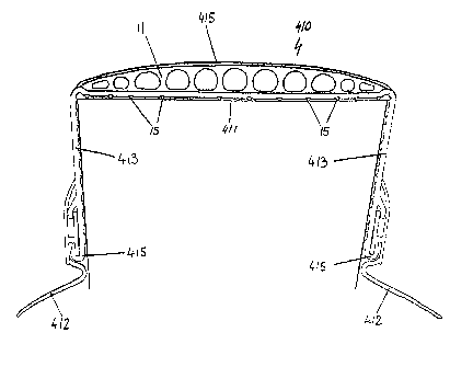
A fourth embodiment of mat 410 is shown in Figures 4a, 4b and 4c. Mat 410 is
similar in
many ways to mat 310, but differs from this mat in that it comprises of either
a single flap
valve 412 or a 'bubble' flap valve 412a, either of which may be supplied as a
separate
component and fixed to locators 415 situated on the fixing legs 413. This
allows the flap to
be manufactured from an alternative suitable material different from the raw
material used
for the mat 410 and it also allows for easy replacement of the flap valves, in
the event of
damage and/or wear, without having to replace the complete mat.
Means may be provided for resisting the tendency of the mat to slip on the
slatted floor.
As shown in Figures 3, 4 a, 4b, 4c, 4d and 4e, such anti-slip means may
comprise
dimples 15 formed on the undersides of the mat and legs which engage the slat.
Other
anti-slip formations will equally be useful and such formations may be
provided with any of
the embodiments of mat description herein
Referring to Figures 4d and 4e, the legs 413 of mat of the fourth embodiment
410 are
shown fitted with detachable flap valves which are provided with a valve
return
mechanism and are adapted to attach to locators 415 situated on fixing legs
413. In
Figure 4d, each valve 416 comprises a pair of rigid flap members 417a, 417b
which are
divergent from flexible joint 418 which provides a valve return mechanism that
enables
valve 416 to pivot thereby allowing the passage of waste material through the
gap in
adjacent slats. A compressible foam material 419 provided in the gap defined
by divergent
flap members 417a, 417b provides a further valve return mechanism which
operates
when a slat having a profile that interferes with the pivoting action of the
valve about
flexible joint 418 is used.
In Figure 4e each valve 416 is shown having an alternative pivoting and valve
return
mechanism. In this arrangement, rigid flap members 417a, 417b are divergent
from
flexible hinge 420 which enables valve 416 to pivot thereby allowing the
passage of waste
material through the gap in adjacent slats. A spring means 421, which is
provided with
suitable means of attachment at its respective ends, extends between the
undersides of
CA 02647649 2014-05-27
9
rigid flaps 417a and 417b, respectively. The spring means 421 provides a
further valve
return mechanism which functions when a slat having a profile that interferes
with the
pivoting action of the valve about flexible joint 418 is used so that a
displaced flap is
returned to its normal closed position once the passage of waste material
through the gap
between adjacent slats is complete. Dashed lines shown in Figures 4d and 4e
indicate
schematically some exemplary alternative slat profiles.
A fifth embodiment of a floor covering apparatus particularly suited, but not
exclusively, to
pigs is indicated generally by reference number 510, is shown in Figures 5a
and 5b. Floor
covering apparatus 510 comprises a domed elastomeric, deformable upper mat
portion
515 fixed to a bed 511 of a plastics material which has sufficient rigidity to
support the
domed elastomeric upper mat portion 515 and sufficient resilient deformability
to enable it
to grip against a slat. Upper mat portion 515 is of a lower profile than the
respective
elastomeric, deformable mat portions of the previous embodiments and comprises
a
domed upper surface that curves downwardly towards the mat edges such that any
urine
and other animal waste matter deposited onto the floor covering apparatus 510
would
tend move towards the gap between adjacent slats. Provision of such a curved
upper
surface may further serve to promote the movement of animal waste from the mat
thereby
increasing the comfort of the animals thereon and also helps preserve the slat
itself by
. 20
reducing absorption of urine into the concrete below. =
Bed 511 includes a pair of laterally depending legs 513 formed in a shape
having a
natural bias to grip the sides of a slat. Each mat also comprises a further
pair of
downwardly extending ancillary legs 514 that are arranged at an acute angle
with legs 5'13
such that they form a secondary flap.
In Figure 5a, elastomeric flap valves 512 which are provided as an integral
component to
mat 511, extend laterally outwardly from the end of each leg 513. Two mutually
adjacent
flap valves 512 ideally extend to reduce the gap between two adjacent slats as
shown in
Figures 5a and 5b or alternatively, may meet in an overlapping manner.
In Figure 5b an alternative variant of the fifth embodiment of a floor
covering apparatus
510 is shown wherein rigid fixing means 516, adapted to receive a separately
demountable flap valve 5'12, are incorporated, either by separate attachment
or by co-
extrusion, onto the distal ends of the laterally depending legs 513.
Separately
CA 02647649 2014-05-27
demountable flap valves 512 comprise an elastomeric flap element 512a and a
base
element 512b such that a flap valve 512 can be attached to depending legs 513
of the mat
bed 511 with the lower edge of base element 512b fastened to fixing means 516
and the
upper edge of base element 512b wedged into the space formed between the
distal end
= 5 of the legs 513 and the ancillary legs 514.
Referring to Figure 5c, an alternative means of attaching a floor covering
apparatus of the
invention to a slat is shown. In the figure the floor covering apparatus is
similar in most
respects to the fifth embodiment 510 of Figures 5a and 5b. However the bed 511
is
10 provided with an additional pair of spaced apart laterally depending
legs 517 which are
adapted to engage with elongate receiving channels 521 that are defined by
member 520
which is provided integrally with slat E. Laterally depending legs 517 are
provided with a
plurality of angled ribs 518 so that said legs may be pressed into receiving
channels 521
with an ensuing mechanical interlocking effect which helps prevent the floor
covering
apparatus from lifting from the slat while in use. In the Figure the floor
coverings are
shown having two mutually adjacent exemplary flap valves 512 extending from
depending
legs 513 minimize or reduce the gap between the valves.
In Figure 5d the means of attaching a floor covering apparatus of the
invention to a slat is
substantially the same as that of Figure 5c. However, The floor covering
apparatus is
segmented into two spaced apart portions, each portion having a sloping
deformable
upper mat portion 515a and a fixed bed 511a which is provided with a first
laterally
depending leg 513a formed in a shape having a natural bias to grip the sides
of a slat and
a second depending leg 517 which engages with a receiving channel 521 of
member 520.
In this arrangement each spaced apart portion is fastened independently to an
opposing
side of a slat with the raised upper surface 522 of member 520 occupying the
gap
between said portions. =
In Figure 5e, a the segmented floor covering apparatus of Figure 5d is shown
fastened
directly to a slat that is pre-formed having elongate receiving channels 531
and a raised
central upper surface 532 such that the floor covering may be fastened
directly to a slat
without the requirement of an integrated member 520 and with raised central
upper
surface 532 occupying the gap between said portions.
CA 02647649 2014-05-27
11
A further embodiment of the invention comprising a separately demountable flap
valve
assembly 600 that is adapted to be fitted to the underside of a slat is shown
in Figures 6a,
6b and 6c. In Figure 6a, flap valve assembly 600 comprises an elongate bed 611
of
material adapted to be fitted to the underside of a slat D by screws or other
suitable
means and having elastomeric flap valves 612 extending laterally outwardly
from its
opposing longitudinal edges. Two mutually adjacent flap valves 612 meet end to
minimize
or reduce the gap between two adjacent slats as shown in Figure 6 or
alternatively, may
meet in an overlapping manner. In Figure 6a a version 600a of flap valve
assembly is also
shown having only a single flap valve 612.
In Figure 6b, an alternative arrangement 600b of a flap valve assembly 600 is
shown
having a bed 611b which is provided with downwardly dependent edges 613 from
which
elastomeric flap valves 612b extend initially inwardly at their respective
proximal ends
before curving divergently outwardly.
In Figure 6c, a further arrangement 600c of the flap valve assembly 600b of
Figure 6b is
shown having a bed 611c which is adapted to engage with a dove-tailed channel
section
620 that may be incorporated into the base of a slat F as indicated in the
Figure.
In Figure 6d, a further alternative arrangement of a flap valve assembly 600b
is shown
comprising a bed 611d which is connected via a hinge 615 to a rigid flap 612d,
the bed
611d being adapted to be fitted to the underside of a slat D. A spring means,
shown as a
flexible bow 616, provided with a suitable means of attachment at its
respective ends
extends between bed 611d and the underside of rigid flap 612d such that a
displaced flap
is returned to its normal closed position once the passage of waste material
through the
gap between adjacent slats is complete.
In Figure 6e a slat G is shown having an integrated member 621 which defines a
pair of
spaced apart locating channels 622 on its opposing sides such that separately
demountable flap valves 612 which each comprise an elastomeric flap element
612a and
a mounting element 612b may be attached to the lower edges of said slat G.
Figure 7 shows an exemplary slat 700 which can be made from concrete, metal,
plastic,
wood or other suitable material and which may be provided with elongate
grooves 702 or
channels having various shapes e.g. dove-tail 701 which may either be pre-
formed or
CA 02647649 2014-05-27
12
incorporated into the slat and adapted to receive complementary shaped
anchoring
formations provided on the respective mats or flap valves.
In Figures 8a and 8b, a sixth embodiment of a floor covering apparatus is
indicated by the
reference numeral 710. Floor covering apparatus 710 comprises a domed
elastomeric,
deformable upper mat portion 715 fixed to a bed 711 of a plastics material
which has
sufficient rigidity to support the domed elastomeric upper mat portion 715 and
an interior
cavity 714 which may be filled with a suitable deformable material. Upper mat
portion 715
is of a lower profile than the respective elastomeric, deformable mat portions
of the
previous embodiments and comprises a donned upper surface that curves
downwardly
towards the mat edges such that any urine and other animal waste matter
deposited onto
the floor covering apparatus 710 would tend move towards the gap between
adjacent
slats. Provision of such a curved upper surface may further serve to promote
the
movement of animal waste from the mat thereby increasing the comfort of the
animals
thereon and also helps preserve the slat itself by reducing absorption of
urine into the
concrete below. In Figure 8b, an alternative arrangement of floor covering
apparatus 710
comprises a bed 711 which includes a pair of laterally depending legs 713
formed in a
shape having a natural bias to grip the sides of a slat.
In Figure 9, a seventh embodiment of a floor covering apparatus is indicated
by the
reference numeral 810. Floor covering apparatus 810 comprises a domed
elastorneric,
deformable upper mat portion 815 fixed to a bed 811 of a plastics material
which has
sufficient rigidity to support the domed elastomeric upper mat portion 815
which may
either be of solid construction or provided with a plurality of elongate holes
816. A bracket
818 which comprises a lower part 818a and flanges 818b extends into the gap
between
adjacent slats D is adapted to engage the respective edges of adjacent mats
810.
Attachment of bracket 818a to mats 810 may be either with flanges 818b
engaging with
recesses 817 provided along the edges of mats 810 or with flanges 818b in
contact with
the surface of the outermost edges of mat upper portion 815. Upon tightening
bolt 821
which extends through bracket 818 and expansion ring 822 into captive member
821
which is wedged between the respective sloping sides of slats D, bracket 818
is forced
downwards thereby clamping mats 810 to slats D.
Further enhancements may be made to any of the aforementioned embodiments of
the
floor covering apparatus to augment the performance of the mats and their
respective flap
CA 02647649 2014-05-27
13
valves as well to as improve the comfort and safety afforded to the livestock
residing
thereon. Mats, 10, 110, 310, 410, 515, 715 and 810 are each suitable to
receive surface
treatments that would include textured embossing or the addition of a further
non-slip grip
surface made from a material applied either in the form of a complete skin or
in the form of
beads or other similar textured features. The inclusion of such surface
treatments would
also contribute to improved durability. The use of resilient elastomeric
materials in the
construction of the flap valves allows the barrier formed by the valves to
return to its
original closed position once urine and other waste materials have passed
through the
floor slats so that gases and odours from a slurry tank below are prevented
from
ascending upwardly though the barrier into the animal housing or reduced
considerably.
Furthermore, employing elastomeric materials having a low friction surface
finish
increases the transfer rate of said animal waste across said flap valves and
into a slurry
tank or similar holding container below.
It is to be understood that the invention is not limited to the specific
details described
herein which are given by way of example only and that various modifications
and
alterations are possible without departing from the scope of the invention as
defined in the
appended claims.