Note : Les descriptions sont présentées dans la langue officielle dans laquelle elles ont été soumises.
CA 02647753 2008-12-23
227580-1
FERRY FLIGHT ENGINE FAIRING KIT
BACKGROUND OF THE INVENTION
The technology described herein relates generally to gas turbine engines, and
more
particularly, to a fairing kit for transporting such engines on ferry flights.
At least one known gas turbine engine assembly includes a fan assembly that is
mounted upstream from a core gas turbine engine. During operation, a portion
of the
airflow discharged from the fan assembly is channeled downstream to the core
gas
turbine engine wherein the airflow is further compressed. The compressed
airflow is
then channeled into a combustor, mixed with fuel, and ignited to generate hot
combustion gases. The combustion gases are then channeled to a turbine, which
extracts energy from the combustion gases for powering the compressor, as well
as
producing useful work to propel an aircraft in flight. The other portion of
the airflow
discharged from the fan assembly exits the engine through a fan stream nozzle.
Gas turbine engines such as described herein are frequently installed on
aircraft in
pairs or multiples, such that in the course of normal operation the aircraft
is propelled
in flight by two, three, four, or more gas turbine engines. With such multi-
engine
installations, the aircraft may in some circumstances be safely operated with
fewer
than all installed engines operating.
In service, gas turbine engines are subject to ordinary wear and tear, as well
as
instances wherein the engine itself may experience unusual wear and tear due
to
external or internal causes which make continued operation of the engine
impossible
or inadvisable. Engines which are in need of service or repair to return to
satisfactory
operating condition frequently must be transported to a suitable service or
repair
facility, which may be located some distance from where the engine was taken
out of
service. To transport the engine, therefore, steps must be taken to remove the
engine
from the aircraft on which it is installed for transportation as cargo or it
must be
transported by the aircraft while still in its installed location.
-1-
CA 02647753 2008-12-23
227580-1
Some aircraft have been configured specifically to carry a non-operating gas
turbine
engine to transport the engine from one location to another, such as to a
location
where it is needed for operation or to a service or repair facility to be
returned to
service. A special fixed or removable mounting pylon may be provided for this
purpose. Other aircraft may be configured so as to be able to transport a non-
operating gas turbine engine in a conventional mounting location.
When a non-operating aircraft gas turbine engine is carried aloft in an
exposed
position on the exterior of an aircraft (as opposed to being carried
internally as cargo
in a transport container), it is exposed to temperature and humidity changes
as well as
precipitation, dirt, debris, and other contaminants which may reach the core
portion of
the engine. Due to the possibility of moisture being present in the core
portion of the
engine after such a journey, a lengthy heating and drying process is normally
required
before the engine can be serviced or operated.
Additionally, the non-operating aircraft gas turbine engine may have internal
parts,
particularly in the core portion of the engine, which have been subject to
wear,
damage, or contamination such that free rotation (or windmilling) of the
engine due to
airflow experienced during a non-operating transport operation may cause
further
wear and/or damage to such parts.
Accordingly, there remains a need for a method for preparing and transporting
non-
operating aircraft gas turbine engines which limits exposure, to moisture and
contamination, and free rotation, from transporting externally on an aircraft.
BRIEF DESCRIPTION OF THE INVENTION
In one aspect, a fairing kit for a gas turbine engine is described. The engine
has a core
gas turbine engine, a fan rotor, and a plurality of external fan blades
attached to the
fan rotor and powered by the core gas turbine engine. The core gas turbine
engine has
an annular splitter for directing a portion of incoming airflow into the core
gas turbine
engine. The fairing kit comprises: a) a fairing; b) a plurality of fasteners
for securing
the fairing to the core gas turbine engine; and c) a conformable seal for
sealing mating
surfaces of the fairing and the core gas turbine engine.
-2-
CA 02647753 2008-12-23
227580-1
BRIEF DESCRIPTION OF THE DRAWINGS
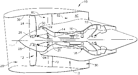
Figure 1 is a cross-sectional illustration of an exemplary gas turbine engine
assembly;
Figure 2 is a partial cross-sectional elevational view of an exemplary gas
turbine
engine, illustrating an exemplary embodiment of a fairing installed on the
engine;
Figure 3 is a cross-sectional view of the fairing of Figure 2 in a
disassembled
condition;
Figure 4 is a partial view of the exemplary gas turbine engine of Figure 1
illustrating
an exemplary borescope motoring pad with a coverplate installed;
Figure 5 is a partial view of the borescope motoring pad of Figure 4 with the
coverplate removed; and
Figure 6 is a perspective view of an exemplary locking plate suitable for use
with the
borescope motoring pad of Figures 4 and 5.
DETAILED DESCRIPTION OF THE INVENTION
Figure 1 is a cross-sectional schematic illustration of an exemplary gas
turbine engine
assembly 10 having a longitudinal axis 11. Gas turbine engine assembly 10
includes a
fan assembly 12 and a core gas turbine engine 13. Core gas turbine engine 13
includes a high pressure compressor 14, a combustor 16, and a high pressure
turbine
18. In the exemplary embodiment, gas turbine engine assembly 10 also includes
a
low pressure turbine 20, and a multi-stage booster compressor 32, and a
splitter 34
that substantially circumscribes booster 32.
Fan assembly 12 includes an array of fan blades 24 extending radially outward
from a
rotor disk 26, the forward portion of which is enclosed by a streamlined
spinner 25.
Gas turbine engine assembly 10 has an intake side 28 and an exhaust side 30.
Fan
assembly 12, booster 22, and turbine 20 are coupled together by a first rotor
shaft 11,
and compressor 14 and turbine 18 are coupled together by a second rotor shaft
22.
In operation, air flows through fan assembly 12 and a first portion 50 of the
airflow is
channeled through booster 32. The compressed air that is discharged from
booster 32
-3-
CA 02647753 2008-12-23
227580-1
is channeled through compressor 14 wherein the airflow is further compressed
and
delivered to combustor 16. Hot products of combustion (not shown in Figure 1)
from
combustor 16 are utilized to drive turbines 18 and 20, and turbine 20 is
utilized to
drive fan assembly 12 and booster 32 by way of shaft 21. Gas turbine engine
assembly 10 is operable at a range of operating conditions between design
operating
conditions and off-design operating conditions.
A second portion 52 of the airflow discharged from fan assembly 12 is
channeled
through a bypass duct 40 to bypass a portion of the airflow from fan assembly
12
around core gas turbine engine 13. More specifically, bypass duct 40 extends
between a fan casing or shroud 36 and splitter 34. Accordingly, a first
portion 50 of
the airflow from fan assembly 12 is channeled through booster 32 and then into
compressor 14 as described above, and a second portion 52 of the airflow from
fan
assembly 12 is channeled through bypass duct 40 to provide thrust for an
aircraft, for
example. Splitter 34 divides the incoming airflow into first and second
portions 50
and 52, respectively. Gas turbine engine assembly 10 also includes a fan frame
assembly 60 to provide structural support for fan assembly 12 and is also
utilized to
couple fan assembly 12 to core gas turbine engine 13.
Fan frame assembly 60 includes a plurality of outlet guide vanes 70 that
extend
substantially radially between a radially outer mounting flange and a radially
inner
mounting flange and are circumferentially-spaced within bypass duct 40. Fan
frame
assembly 60 may also include a plurality of struts that are coupled between a
radially
outer mounting flange and a radially inner mounting flange. In one embodiment,
fan
frame assembly 60 is fabricated in arcuate segments in which flanges are
coupled to
outlet guide vanes 70 and struts. In one embodiment, outlet guide vanes and
struts are
coupled coaxially within bypass duct 40. Optionally, outlet guide vanes 70 may
be
coupled downstream from struts within bypass duct 40.
Fan frame assembly 60 is one of various frame and support assemblies of gas
turbine
engine assembly 10 that are used to facilitate maintaining an orientation of
various
components within gas turbine engine assembly 10. More specifically, such
frame
and support assemblies interconnect stationary components and provide rotor
bearing
supports. Fan frame assembly 60 is coupled downstream from fan assembly 12
-4-
CA 02647753 2008-12-23
227580-1
within bypass duct 40 such that outlet guide vanes 70 and struts are
circumferentially-
spaced around the outlet of fan assembly 12 and extend across the airflow path
discharged from fan assembly 12.
Figure 2 is a partial cross-sectional elevational view of the forward portion
of an
exemplary aircraft gas turbine engine such as depicted in Figure 1. As shown
in
Figure 2, a fairing 80 has been installed on the core gas turbine engine 13 in
place of
the spinner 25 and the fan blades 24 which have been removed and stored
separately
for transportation. In the embodiment shown in Figure 2, the fairing 80 is of
two-
piece construction, comprising an inner portion 82 and an outer portion 84.
Inner
portion 82 and outer portion 84 are joined to one another as well as to the
fan rotor 26
by bolts or other suitable fasteners 88 and suitably located mounting holes
provided in
the fairing components. Mounting holes 27 in the fan rotor 26, such as may
typically
be used to fasten the spinner 25 in place, may be utilized to secure the
fairing 80 via
fasteners 88.
Depending upon the physical configuration of the gas turbine engine upon which
the
fairing 80 is to be installed, the fairing may be of one-piece (i.e., unitary)
construction
or multi-piece (i.e., two or more pieces) construction. The fairing 80 has a
generally
streamlined shape, typically of rounded conical or bullet-shaped design, to
minimize
drag on the engine during transport. The elements of the fairing are sized,
shaped,
and adapted to suit the characteristics of the particular engine application
desired.
Figure 3 is a cross-sectional elevational view of the fairing 80, similar to
the view of
Figure 2 but showing the fairing 80 in a disassembled condition and depicting
the
relationship of inner and outer portions 82 and 84, respectively. In the
embodiment
shown, the outer portion 84 is of annular configuration and surrounds and is
secured
to the inner portion 82. Also shown in Figure 3 is an annular seal 86, which
may be
formed from rubber, foam, plastic, or other conformable material, which abuts
and
forms a substantially if not fully airtight seal against splitter 34 when the
fairing 80 is
installed on the core gas turbine engine 13. Other configurations may be
possible
wherein the annular seal 86 is integrally formed with the fairing 80, such as
wherein
the fairing 80 is formed from a material which is suitably compliant so as to
conform
to and sealingly engage the splitter 34.
-5-
CA 02647753 2008-12-23
227580-1
For the embodiment shown in Figures 2 and 3, the fairing 80 is installed after
removing and separately storing the spinner 25 and fan blades 24. The inner
portion
82 of the fairing 80 is installed on the fan rotor 26 via mounting holes 27
and a
plurality of fasteners 88. The outer portion of the fairing 84 is then
installed over and
around the inner portion 82 and is fastened to the inner portion 82 via
fasteners 88.
As the outer portion 84 is secured in position, outer portion 84 moves axially
toward
the core gas turbine engine and the annular seal 86 comes into contact with
and
sealingly engages the forward portion of the splitter 34, so as to seal the
opening of
the booster 32 and prevent introduction of moisture, contaminants, and airflow
into
the booster 32 and thus into the core gas turbine engine 13. As such, for the
embodiment shown the process of securing the fairing 80 to the core gas
turbine
engine is a two phase operation wherein the first portion is secured first,
followed by
the second portion.
By effectively sealing the front of the booster 32, the fairing 80 prevents
air from
flowing through the booster 32 during flight and imparting any rotational
forces to the
booster 32 (and any other rotating turbomachinery or accessories which share
shaft 21
with booster 32). Air is also prevented from flowing through the compressor
14, as
well as through both high pressure turbine 18 and low pressure turbine 20, and
thereby
avoiding imparting any rotational forces to those components (and any other
rotating
turbomachinery or accessories connected to shafts 21 or 22).
Additionally, the sealing engagement of the fairing 80 with the splitter 34
coupled
with the mechanical engagement of the fairing 80 with the fan rotor 26 (via
fasteners
88) provides mechanical resistance to rotation for fan rotor 26 and any other
components within the core gas turbine engine 13 which are associated with the
shaft
21 to which the fan rotor 26 is attached.
Many aircraft gas turbine engines have a location where a device can be
attached to
rotate the core gas turbine engine 13 for inspection and/or service
operations, such as
borescope inspection. This location (shown in Figures 4 and 5) is commonly
referred
to as a borescope motoring or turning pad 90. Borescope motoring pad 90 is a
location where a coverplate 92 can be removed via fasteners 94 (such as bolts,
pins,
screws, or other fasteners) to expose a socket 96 which is adapted for
engagement by
-6-
CA 02647753 2008-12-23
227580-1
a tool (such as a%2 inch square drive ratchet, wrench, or bar) or a motorized
drive
assembly to rotate the core gas turbine engine 13 through a suitable gearbox
assembly.
To provide additional optional mechanical security against rotation of the
core gas
turbine engine 13 during a transport operation, a rotor lock 91 of suitable
configuration for the particular engine application may be utilized. Such a
rotor lock
has suitable mounting holes 93, a seal 95, and a knob 97 of suitable
configuration to
engage the socket 96. The rotor lock 91 may be installed on the borescope
motoring
pad 90, engaging the socket 96 and sealing the opening via seal 95, and
secured in
place via fasteners 94, thereby mechanically preventing rotation of the socket
96 and
all other rotating parts mechanically coupled to the socket 96. Rotor locks
such as
rotor lock 90 may be fabricated of any suitable material, such as metallic or
composite
materials, having suitable strength to resist turning motion of the socket 96.
In the exemplary embodiment, the fairing 80 may be a fiberglass material, a
graphite
material, a carbon material, a ceramic material, an aromatic polyamid material
such as
KEVLAR, a thin metallic material such as, but not limited to, titanium,
aluminum,
and/or a Metal Matrix Composite (MMC) material, and/or mixtures thereof. Any
suitable thermosetting polymeric resin can be used in forming fairing 80, for
example,
vinyl ester resin, polyester resins, acrylic resins, epoxy resins,
polyurethane resins,
bismalimide resin, and mixtures thereo Overall, the material is selected such
that an
exterior surface of fairing 80 is resistant to wear and or damage that may be
caused by
foreign objects ingested into gas turbine engine assembly 10. Alternate
fairing
configurations may use a thin metal wrap over a composite fairing to protect
against
such wear or damage.
This written description uses examples to disclose the invention, including
the best
mode, and also to enable any person skilled in the art to make and use the
invention.
The patentable scope of the invention is defined by the claims, and may
include other
examples that occur to those skilled in the art. Such other examples are
intended to be
within the scope of the claims if they have structural elements that do not
differ from
the literal language of the claims, or if they include equivalent structural
elements
with insubstantial differences from the literal languages of the claims.
-7-