Note : Les descriptions sont présentées dans la langue officielle dans laquelle elles ont été soumises.
CA 02648807 2008-10-09
, .. r
INJECTION-MOLDING NOZZLE SHANK SYSTEM AND
A METHOD FOR MANUFACTURING SUCH A SYSTEM
The present invention relates to an injection-molding nozzle shank-system
defined in
claim 1, to a hot runner nozzle defined in claim 21 and to a method defined in
claim 22 for
manufacturing such an injection-molding shank system..
Injection molding nozzles are used in injection molding equipment to feed a
fluid/flowable injection material at a predetermined temperature and high
pressure to a
separable mold insert. The injection material passing through the flow duct
system must be
kept fluid until it reaches the mold insert, therefore requiring accurate
temperature control,
while on the other hand said injection material must rapidly solidify inside
the mold, in order
to maintain short, economical operational cycles. Therefore heat losses from
the mostly hot
nozzle to the cold mold must be minimized, especially in the zone of the
nozzle tip.
The document EP 0 927 617 B1 discloses a hot runner nozzle fitted with an
externally heated injection material feeding pipe comprising at its end a
nozzle tip. To attain
uniform temperature distribution and to minimize heat losses, this injection
material feeding
pipe is mounted in a shank-like housing fitted at the lower zone of the
injection material
feeding pipe with a thermally poorly conducting cap. Said cap touches the mold
only at a
site far away from the nozzle tip and by its lower end constitutes a seat
allowing the injection
material feeding pipe to be centrally guided within it and thermally
insulating said pipe in the
nozzle tip zone from the mold. However different equipment thermal
expansions/contractions
arise during at the injection material feeding pipe and the shank cap,
resulting in relative
displacements, with danger that there may be substantial wear of the soft,
thermally poorly
conducting cap, and hence leakage.
1
CA 02648807 2008-10-09
The German patent document 41 27 036 Cl therefore proposes a multi-step shank
system enclosing the injection material feeding pipe, comprising an outer
sheath tube made
of a high-strength tool steel and fitted with an adjoining spacer tube made of
a low thermally
conducting substance such as a chromium nickel steel, and an annular end zone
made of a
high-strength tool steel. This design does in fact reduce the wear between the
end zone and
the injection material feeding pipe. On the other hand the substance selection
of the
thermally poorly conducting separation tube is limited because,
illustratively, titanium and
steel cannot be welded to each other and screw connections would be cumbersome
and
costly.
Accordingly it is the objective of the present invention to eliminate the
above cited
and other drawbacks of the state of the art and to create a design for an
injection-molding
nozzle shank system allowing simple and economic manufacture and always
providing
optimal thermal insulation. Moreover the wear of the annular end zone shall be
further
reduced to assure unfailingly reliable operation of the injection molding
nozzle. Moreover
the manufacture of the shank system shall be both simple and economical.
The main features of the present invention are defined in claims 1, 21 and 22.
Embodiments of the present invention are defined in claims 2 through 20 and 23
through 28.
Regarding an injection-molding nozzle shank system comprising a heated
injection
material feeding pipe fitted at its end with a nozzle tip consisting of a main
shank part, a
thermally insulating spacer part and a shank terminal part, where the shank
main part and
the spacer part enclose the injection material feeding pipe while being
radially spaced from it
and the shank terminal part constitutes a recess receiving in sealing manner
the free
2
CA 02648807 2008-10-09
injection material feeding pipe, the present invention provides that the shank
main part, the
spacer part and the shank terminal part are soldered to each other and that
the terminal
shank part is hardened.
In this manner optimal resistance to wear is always attained in the spacer
part's end
zone without thereby degrading the spacer part's thermal insulation
effectiveness. The
injection molding nozzle always is optimally tight and thereby permanently
reliable injection
molding nozzle operation is assured.
A hot runner nozzle fitted with a shank system of the present invention offers
the
advantage of always operating reliably because the hardened steel ring in the
titanium cap
protects it against frictional wear due to contact with the injection material
feeding pipe.
The present invention also relates to a method for manufacturing an injection-
molding nozzle shank system comprising an externally heated injection material
feeding
pipe fitted at its end with a nozzle tip, said shank system being constituted
by a main shank
part, a thermally insulating spacer part and a terminal shank part, said main
shank part and
the said spacer part enclosing the injection material feeding pipe at a radial
distance from it,
the terminal shank part subtending a recess receiving in sealing manner the
free end of the
injection material pipe, and said invention provides that the main shank part,
the spacer part
and the terminal shank part are soldered to each other and that the terminal
shank part shall
be hardened in the soldering process.
This surprisingly simple method of the invention also allows both rapid and
efficient
manufacture of shank systems. The components of said systems are connected to
each
3
CA 02648807 2008-10-09
other by soldering, the hardening procedure subsequent to soldering imparting
high wear
resistance to the terminal shank part.
Further features, details and advantages of the present invention are defined
by the
appended claims and elucidated in the following description of illustrative
embodiment
modes in relation to the attached drawings.
Fig. I is a lateral section of a shank system for a hot runner nozzle prior to
final
processing, and
Fig. 2 is a lateral section of another shank system for a hot runner nozzle
after final
processing.
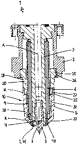
The injection molding nozzle denoted by the overall reference 1 in Fig. 1 is
designed
to be used in an otherwise omitted injection molding apparatus serving to
manufacture
molded components from a fluid/flowable material -- for instance a plastic
melt. Typically the
injection molding apparatus comprises a clamping plate and parallel to it a
manifold plate
which is fitted with an array of flow ducts. The latter issue into several
injection molding
nozzles 1 which illustratively are designed as hot runner nozzles and which
each are
mounted by means of a housing 2 to the underside of the manifold plate.
An injection material feeding pipe 3 is inserted into each housing 2 and is
fitted at its
outer periphery with an electric heater 6. The injection material feeding pipe
3 ends in a
nozzle tip 5 subtending terminally a nozzle discharge aperture 7. The material
being
processed is fed through said aperture and through an omitted sprue opening
into a
separable mold inset (also omitted).
4
CA 02648807 2008-10-09
In order to thermally shield the injection material pipe 3 and the heater 6
from the
mold plates, the housing 2 continues in the direction of the nozzle tip 5 by a
shank system
10. This shank system comprises a main shank part 20 made of a hardened tool
steel, a
cap-shaped spacer part 30 of a substance of low thermal conductivity and an
annular,
terminal shank part 40 also made of a hardened tool steel. Said terminal part
constitutes a
recess 41 having a substantially cylindrical inner contour I enclosing in
sealing manner the
free end 4 of the injection feeding pipe 3 in the displacement seat while the
main shank part
20 and the spacer part 30 enclose the injection material feeding pipe 3 at a
radial distance
from it, as a result of which there remains a thermally insulating air gap 9 --
except for a
narrow rest site 8 of the heater 6 against the spacer part 30 -- between the
heater 6 and the
shank system 10.
The overall cylindrical main shank part 20 is fitted at its upper end 25 with
an external
thread 26 by means of which it is screwed from below into the housing 2. The
lower end 27
of the main shank part 20 is stepped and soldered to the upper end 35 of the
spacer part 30.
For that purpose said spacer part is fitted at its end face with a muff-like
recess 32 receiving
the lower end 27 of the upper shank part 20. At the same time the lower end 37
of the
spacer part 30 constitutes also a stepped recess 31 receiving the terminal
shank part 40.
Said terminal part and the spacer part 30 also are soldered to each other.
Figs. 1 and 3 show that the mutually soldered shank parts 20, 30, 40 jointly
with the
housing 2 are configured concentrically to the longitudinal axis A of the hot
runner nozzle 1
and are fitted peripherally with an external processing contour K. Said
contour subtends a
step S approximately at half height of the spacer part 30, as a result of
which the overall
5
CA 02648807 2008-10-09
conically portion 38 of the cap 30 enclosing the terminal nozzle zone is
seated free of
contact in the mold. Accordingly a free space remains between the conical
terminal portion
38 of the cap 30 that extends flush with the terminal shank part 40 and the
mold, said space
being able to receive injection material to be processed during operation of
the hot runner
nozzle 1. This feature enhances the insulating effect of the spacer part cap
30.
The external contour K is cylindrical above the step S. This zone is both a
snug fit in
the mold and a sealing and centering surface. To reliably preclude the highly
pressurized
plastic melt to be injected from penetrating the upper zone of the shank 10,
the outer contour
K of the shank 10 is provided below the thread 26 with a fit 28 in the form of
a radial
elevation. This elevation reliably seals the shank 10 from the mold and at the
same time
enhances centering the nozzle 1 in the mold.
As indicated, the main shank part 20 constitutes an upper shank part that can
be
screwed to the housing 2 of the injection molding nozzle 1. The spacer part 30
constitutes a
cap which is preferably made of titanium or a similarly thermally poorly
conducting substance
and which at its end receives the terminal shank part 40. Preferably this
terminal shank part
40 is annular and made of a tool steel which can be hardened. Preferably the
upper shank
part 20 is made of the same tool steel.
Whereas the shank system 10 is shown in Figs. 1 and 3 in its final assembly
form,
in Fig. 2 the shank parts 20, 30, 40 yet to be soldered together are shown in
the initial state
of such assembly.
The spacer cap 30 is mounted on the upper shank part 20 which is fitted end-
side
with a recess 21 for the muff-like end 35 of the spacer cap 30. Said end 35
receives the
6
CA 02648807 2008-10-09
stepped end portion 27 of the upper shank part 20, the components 20, 30
mechanically
interlocking each other axially and radially down to an omitted gap between
them. A solder
repository 23 is constituted in the zone of the recess 21 of the upper shank
part 20
peripherally next to the spacer cap 30 and receives an annular solder element
24.
The terminal shank part 40 is in the form of a steel ring and comprises a
stepped
external contour by means of which it is seated in geometrically interlocking
manner in the
end-side recess 31 of the spacer cap 30, a small gap remaining between latter
and the steel
ring 40. A further solder repository 33 is peripherally constituted next to
the steel ring 40 and
receives an annular solder element 34.
The end-side stepped recesses 21, 31, 32 in the upper shank part 20 and in the
spacer part cap 30 assure that the shank system 10 can be mounted vertically,
that is, the
ring 40 and the spacer cap 30 are axially secured. Where called for the end-
side recesses
21, 31, 32 also may be partly conical to enhance centering the components 20,
30, 40. The
size of the gap between the shank parts 20, 30 respectively 30, 40 is between
0.02 and 0.2
mm to allow the solder 24, 34 to access, during soldering, the gaps between
the
components 20, 30, 40.
The shank parts 20, 30, 40 are soldered by placing the shank system 10 shown
in
Fig. 2 in an omitted soldering oven and heating them to the soldering
temperature. The
solder 24, 34 received in the solder repositories 23, 33 then melts and enters
the gap
between the shank upper part 20, the spacer part cap 30 and the steel ring 40
until, by
capillarity, said gap has been entirely filled with solder.
7
CA 02648807 2008-10-09
The annular shank terminal part 40 is made of tool steel and already is
hardened
during soldering because, in the present invention, the selected soldering
temperature is
situated in the range of the transformation temperature of the particular
selected tool steel of
the main shank part 20 and the terminal shank part 40.
Following soldering, the terminal zone of the shank system 10 and hence of the
terminal shank part 40 is quenched in a water or oil bath and then is
tempered.
Following this treatment, the shank parts 20, 30, 40 are ground into their
external
processing contour K. The recess 41 of the terminal shank part 40 is fitted
with the inside
processing contour I in a manner that the injection material feeding pipe 3 is
always guided
in sealed manner in the steel ring 40 terminally inserted into the spacer part
cap 30. Said
ring 40 having been hardened by the soldering and processing procedure, the
inevitable
relative motion between the shank system 10 and the injection material feeding
pipe 3 no
longer entails undue wear. The entire system is sealed permanently, always
assuring
reliable injection molding nozzle operation. Moreover the injection material
feeding pipe 3 is
optimally thermally insulated, in particular in the zone of the nozzle tip 5,
so that heat losses
are all but precluded.
The present invention is not restricted to the above described embodiment
modes,
instead it may be modified in many ways. It must be borne in mind however that
a shank
system 10 for an injection molding nozzle 1 with a heated injection material
feeding pipe 3
fitted end-side with a nozzle tip 5 comprises a main shank part 20, a
thermally insulated
spacer part 30 and a terminal shank part 40, the main shank part 20 and the
spacer part 30
enclosing the injection material feeding pipe 3 while subtending a radial gap
to it, whereas
8
CA 02648807 2008-10-09
the terminal shank end 40 subtends a recess 41 receiving in sealing manner the
free end of
the injection material feeding pipe 3. At their end sides, the main shank part
20, the spacer
part 30 and the terminal shank part 40 are fitted with recesses 21, 31, 32 for
at least one
adjacent shank part 20, 30, 40. They each comprise moreover, prior to
fashioning an
external processing contour K, a solder repository 23, 33 receiving annular
solder elements
24, 34 in order that all three components 20, 30, 40 be soldered together. The
annular
terminal part 40 is hardened by the very soldering procedure in order to
enhance resistance
to wear, the soldering temperature being in the range of the transformation
temperature of
the substance of the terminal shank part 40.
All features and advantages, inclusive design details, spatial configurations
and
method steps implicit and explicit in the claims, specification and drawings,
of the present
disclosure, lend themselves to being construed inventive per se as well as in
the most
diverse combinations.
9
CA 02648807 2008-10-09
LIST OF REFERENCES
A longitudinal axis 24 solder
I inside processing contour 25 upper end
K outside processing contour 26 thread
27 lower end
1 injection molding nozzle/hot-runner 28 fit
nozzle
2 housing 30 spacer part / cap
3 injection material feeding pipe 31 recess
4 free end 32 recess
nozzle tip 33 solder repository
6 heater 34 solder
7 nozzle discharge aperture 35 upper end
8 rest site 37 lower end
9 air gap 38 conical segment
shank system 40 terminal shank end / ring
main shank part/upper shank part 41 recess / displacement seat
21 recess
23 solder repository