Sélection de la langue

Search

Sommaire du brevet 2649536 

Énoncé de désistement de responsabilité concernant l'information provenant de tiers

Une partie des informations de ce site Web a été fournie par des sources externes. Le gouvernement du Canada n'assume aucune responsabilité concernant la précision, l'actualité ou la fiabilité des informations fournies par les sources externes. Les utilisateurs qui désirent employer cette information devraient consulter directement la source des informations. Le contenu fourni par les sources externes n'est pas assujetti aux exigences sur les langues officielles, la protection des renseignements personnels et l'accessibilité.

Disponibilité de l'Abrégé et des Revendications

L'apparition de différences dans le texte et l'image des Revendications et de l'Abrégé dépend du moment auquel le document est publié. Les textes des Revendications et de l'Abrégé sont affichés :

  • lorsque la demande peut être examinée par le public;
  • lorsque le brevet est émis (délivrance).
(12) Brevet: (11) CA 2649536
(54) Titre français: JAMBE DE FORCE POUR TURBINE A GAZ
(54) Titre anglais: STRUT FOR A GAS TURBINE ENGINE
Statut: Périmé et au-delà du délai pour l’annulation
Données bibliographiques
(51) Classification internationale des brevets (CIB):
  • F01D 09/02 (2006.01)
(72) Inventeurs :
  • MARINI, REMO (Canada)
  • VLASIC, EDWARD (Canada)
  • FINDLAY, JONATHON PETER (Canada)
(73) Titulaires :
  • PRATT & WHITNEY CANADA CORP.
(71) Demandeurs :
  • PRATT & WHITNEY CANADA CORP. (Canada)
(74) Agent: NORTON ROSE FULBRIGHT CANADA LLP/S.E.N.C.R.L., S.R.L.
(74) Co-agent:
(45) Délivré: 2012-09-04
(22) Date de dépôt: 2009-01-13
(41) Mise à la disponibilité du public: 2009-12-30
Requête d'examen: 2009-01-13
Licence disponible: S.O.
Cédé au domaine public: S.O.
(25) Langue des documents déposés: Anglais

Traité de coopération en matière de brevets (PCT): Non

(30) Données de priorité de la demande:
Numéro de la demande Pays / territoire Date
12/164,565 (Etats-Unis d'Amérique) 2008-06-30

Abrégés

Abrégé français

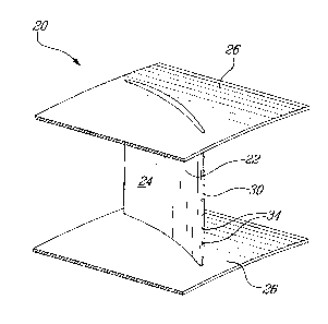
Cette jambe de force conçue pour un moteur à turbine à gaz a un corps ayant habituellement la forme d'un profilé aérodynamique pourvu d'un bord d'attaque et d'un bord de fuite. Le bord d'attaque a au moins un orifice d'admission en communication fluidique directe avec au moins un orifice de sortie, situé sur le bord de fuite, par lequel les gaz peuvent être redirigés du bord d'attaque vers le bord de fuite, à travers la jambe de force, pour être réinjectés dans une région de sillage en aval de la jambe de force.


Abrégé anglais

The strut is for use in a gas turbine engine has body, typically having an airfoil shape, having a leading edge and a trailing edge. The leading edge has at least one gas inlet in direct fluid communication with at least one outlet located in the trailing edge through which gas may be redirected from the leading edge to the trailing edge through the strut for injection back into a wake region downstream of the strut.

Revendications

Note : Les revendications sont présentées dans la langue officielle dans laquelle elles ont été soumises.


7
CLAIMS:
1. A method of reducing wake loss of a strut spanning a gas path of a gas
turbine engine, the method comprising the steps of:
ingesting gas from a gas path flow into the strut through a leading edge of
the strut; and
discharging the ingested gas flow back into the gas path through the trailing
edge of the strut to increase gas pressure in a wake region and thereby
decrease strut wake loss.
2. The method of claim 1 wherein the step of ingesting includes ingesting gas
through a plurality of apertures located at a stagnation point of the leading
edge of the strut.
3. The method of claim 1 wherein the ingested gas flow is passed in a
substantially straight line from a point of ingestion to a point of discharge.
4. The method of claim 1 further comprising using a pressure difference
between the strut leading and trailing edges to drive the ingested flow
through the strut.
5. The method of claim 1 further comprising using the strut exterior shape to
at
least partially deswirl the gas path flow.
6. A gas turbine engine comprising:
an annular gas path defined through the engine; and
at least one strut extending generally radially relative to the engine from an
inner gas path wall to an outer gas path wall, the strut thereby spanning
the gas path, the strut having a leading edge with at least one inlet
aperture, a trailing edge with at least one outlet aperture and at least
one internal passageway extending through the strut between the
leading edge and trailing edge apertures, wherein the passageway

8
extends in a substantially unobstructed line between the inlet and
outlet apertures.
7. The gas turbine engine of claim 6 wherein the passageway provides a
substantially straight line path between the inlet and outlet apertures.
8. The gas turbine engine of claim 6 wherein the strut has a cross-sectional
shape which is substantially airfoil-shaped.
9. The gas turbine engine of claim 6 wherein the strut spans the gas path
downstream of a final outlet of a turbine section.
10. The gas turbine engine of claim 6 wherein the strut spans the gas path
upstream of a combustor section.
11. The gas turbine engine of claim 6 wherein the gas path is defined through
a
bypass duct of a turbofan engine.
12. The gas turbine engine of claim 6 wherein the at least one inlet aperture
comprises a plurality of inlet apertures.
13. The gas turbine engine of claim 12 wherein the at least one passageway is
a
single passageway communicating with the plurality of inlet apertures.
14. The gas turbine engine of claim 6 wherein the at least one inlet aperture
is
located at a leading edge stagnation point of the strut.
15. The gas turbine engine of claim 6 wherein the strut is in a turbine
exhaust
case.
16. The gas turbine engine of claim 15 wherein the strut is a deswirler
configured to deswirl the gas path flow prior to the exiting the engine.

9
17. A gas turbine engine comprising:
an annular gas path defined through the engine; and
at least one strut extending generally radially relative to the engine from an
inner gas path wall to an outer gas path wall, the strut thereby spanning
the gas path, the strut having a leading edge with a plurality of inlet
apertures and a trailing edge with plurality of outlet apertures, the strut
composed of a peripheral wall enveloping a substantially unobstructed
space therein, the substantially unobstructed space providing an open
internal passageway extending through the strut fluidly connecting the
leading edge and trailing edge apertures.
18. The gas turbine engine of claim 17 wherein the strut is provided in a
turbine
exhaust case downstream of a final exit of a turbine section of the engine.
19. The gas turbine engine of claim 17 wherein the inlet apertures are located
at
a leading edge stagnation point of the strut.
20. The gas turbine engine of claim 17 wherein the inlet apertures are sized
and
configured to ingest air from the gas path.

Description

Note : Les descriptions sont présentées dans la langue officielle dans laquelle elles ont été soumises.


CA 02649536 2009-01-13
1
STRUT FOR A GAS TURBINE ENGINE
TECHNICAL FIELD
The field of the invention generally relates to struts for use in gas turbine
engines.
BACKGROUND
Struts are circumferentially-disposed, radially-extending elements spanning a
gas path
of a gas turbine engine and are used for structural purposes and/or to
redirect (i.e. de-
swirl or pre-swirl) the gas path flow. Struts may be used either in the
compressor
section or the turbine section, however no matter where the location,
inevitably the
presence of struts creates losses. One major source of loss created by the
struts is the
wake due to the presence of the finite trailing edge - unlike turbine or
compressor
blades or vanes which have very thin trailing edges, gas path struts tend to
have larger
trailing edge thicknesses, which exacerbates wake losses. Therefore there is
room for
improvement in strut design.
SUMMARY
In one aspect, the present concept provides a method of reducing wake loss of
a strut
spanning a gas path of a gas turbine engine, the method comprising the steps
of
ingesting gas from a gas path flow into the strut through a leading edge of
the strut,
and discharging the ingested gas flow back into the gas path through the
trailing edge
of the strut to increase gas pressure in a wake region and thereby decrease
strut wake
loss.
In another aspect, the present concept provides a gas turbine engine
comprising: an
annular gas path defined through the engine; and at least one strut extending
generally
radially relative to the engine from an inner gas path wall to an outer gas
path wall, the
strut thereby spanning the gas path, the strut having a leading edge with at
least on
inlet aperture, a trailing edge with at least on outlet aperture and at least
one internal
passageway extending through the strut between the leading edge and trailing
edge
DOCSMTL: 3112067\1

CA 02649536 2009-01-13
2
apertures, wherein the passageway extends in a substantially unobstructed line
between the inlet and outlet apertures.
In a further aspect, the present concept provides a gas turbine engine
comprising: an
annular gas path defined through the engine; and at least one strut extending
generally
radially relative to the engine from an inner gas path wall to an outer gas
path wall, the
strut thereby spanning the gas path, the strut having a leading edge with a
plurality of
inlet apertures and a trailing edge with plurality of outlet apertures, the
strut composed
of a peripheral wall enveloping a substantially unobstructed space therein,
the
substantially unobstructed space providing an open internal passageway
extending
through the strut fluidly connecting the leading edge and trailing edge
apertures..
Further details of these and other aspects will be apparent from the detailed
description and figures included below.
DESCRIPTION OF THE FIGURES
Reference is now made to the accompanying figures, in which:
Fig. 1 is gas turbine engine including a strut according to the present
teachings;
Fig. 2 is isometric view of a portion of the turbine exhaust case of the
engine of Fig. 1,
showing an example of the strut as viewed from its leading edge side;
Fig. 3 shows the strut of Fig. 2, as viewed from a trailing edge side;
Fig. 4 is a cross-sectional view of the strut shown in Fig. 2;
Fig. 5 is an enlarged cross-sectional view of the leading edge of the strut
shown in
Fig. 2; and
Fig. 6 is a view similar to Fig. 5, showing the trailing edge of the strut
shown in
Fig. 2.
DETAILED DESCRIPTION
Fig. 1 illustrates a gas turbine engine 10 of a type preferably provided for
use in
subsonic flight, generally comprising in serial flow communication a fan 12
through

CA 02649536 2009-01-13
3
which ambient air is propelled, a multistage compressor 14 for pressurizing
the air, a
combustor 16 in which the compressed air is mixed with fuel and ignited for
generating an annular stream of hot combustion gases, and a turbine section 18
for
extracting energy from the combustion gases. Downstream of the turbine section
18 is
a turbine exhaust case (unindicated) which includes a plurality of struts 20
in
accordance with the teachings hereinbelow.
Figs. 2 to 6 show an example of a single such strut 20. As depicted in Figure
1, this
strut 20 can be used as a de-swirl exhaust flow in a turbine exhaust case
downstream
of the turbine section 18 of the gas turbine engine 10, although application
of the
present teachings is not limited to turbine deswirlers. Fig. 2 shows that the
strut 20
comprises in this example an airfoil 22 having sidewalls 24 extending between
two
radially spaced-apart platforms 26. The airfoil 22 has a leading edge (LE) 30
and a
trailing edge (TE) 32 with reference to the airflow through the gas path of
the engine.
Fig. 2 shows the strut 20 as it appears from its leading edge 30 and Fig. 3
shows the
strut 20 as it appears from its trailing edge 32. A plurality of such struts
20 are
conventionally disposed circumferentially side-by-side to form a annular array
around
the turbine exhaust case assembly. Fabrication of the struts can be done by a
combination of casting, machining and welding.
Typically a plurality of larger cross-sectioned structural struts in the array
are
interspersed by a larger number of deswirler struts. The structural struts
(not shown)
typical also have an airfoil cross-sectional shape to some extent, although
usually with
a much greater chord. Some structural struts may have a simple elliptical
shape, or
hybrid of an ellipse and an airfoil. Regardless of shape or function, the
present
teachings may be suitably applied.
The strut 20 has a plurality of inlet holes 34 in the leading edge 30, each
holes 34
preferably located at the nominal location of LE stagnation point of the
airfoil. A
plurality of outlet holes 36 are also provided in the trailing edge 32, also
preferably at
the nominal location of the TE stagnation point. The numbers, positioning,
shaping,
spacing, sizing, etc of the holes are selected by the designer to provide the
desired

CA 02649536 2009-01-13
4
performance characteristics, as will be appreciated by he reader in light of
the
teachings herein. For example, holes 34 may comprise slots, rather than
circular
holes. A single substantially continuous slot may be desired instead of a
plurality of
discrete openings. And so on, the designer has latitude to design a system
suitable to
the application at hand.
Referring to Figure 4, the holes 34, 36 are in direct fluid communication with
each
other through one or more chordwise-extending passageways 40 within the
airfoil 22.
The inlet holes 34, the passageway or passageways 40 and the outlet holes 36
are
designed so as to minimize pressure losses as much as possible for air passing
therethrough, that is the passageways are preferably substantially
unobstructed and
designed to minimize flow losses as much as necessary to facilitate the
desired flow of
gas through the strut, as will be described further below. Figs. 5 and 6 are
enlarged
views of a representative hole 34 at the leading edge 30 and a representative
hole 36 at
the trailing edge 32, respectively.
In use, as the gas turbine engine is operated, a flow of gas passes around the
strut (in
this example, the flow is turbine exhaust exiting the turbine portion of the
engine).
When a gas flow approaches the strut, the flow separates to pass around either
side of
the strut, and then the flow reattaches downstream of the strut. This action
tends to
create a wake effect at the trailing edge. However, a portion of the gas path
flow at
the leading edge 30 is ingested into the strut through holes 34, and passed to
the
trialing edge holes 36 though passage(s) 40, which tends to energize the wake
caused
by the strut, and thereby tends to reduce the wake loss. Gas from the
mainstream is
thus allowed to travel through holes or slots located at the leading edge of
an array of
struts and out through holes or slots located at the trailing edge. The
resultant flow,
driven by the pressure difference between strut leading and trailing edges, is
injected
at the wake location and is preferably injected in sufficient quantity to
increase the
base pressure in the wake zone and thereby reduce the loses produced by the
finite
trailing edge thickness.

CA 02649536 2009-01-13
Although it is known to provide cooled turbine blades and vanes with holes
aligned
along a leading or trailing edge of the airfoil, it is important to note that
such holes in
cooled blades/vanes are used for the purpose of exhausting cooling air from
within the
airfoil cavity to the gas path. It is also important to understand, as the
skilled reader
5 will, that ingestion of gas path air into such cooled turbine blades/vanes
is to be
avoided, as it has a detrimental impact on the durability due to the extremely
high
temperatures present within the turbine section. As such, turbine blade/vane
leading
edge holes are, for example, designed to avoid air ingestion, i.e. to avoid
allowing air
to enter into the interior of the blade/vane. In contrast, one will observe
that struts of
the type described herein are uncooled (e.g. no cooling air is independently
provided
to the strut interior), and that the placement of the present struts outside
the turbine
section of the engine (e.g. downstream of the turbine section in a turbine
exhaust case,
or in a compressor section upstream of the combustor, or in a bypass section
of the
engine) presents a different set of design concerns than those facing the
turbine
blade/vane designer. Therefore, in contrast to the teachings generically
available in
the turbine blade/vane art, gas ingestion is encouraged in the present
approach to re-
use the ingested flow to energize the TE wake.
The above description is meant to be exemplary only, and one skilled in the
art will
recognize that changes may be made to the embodiments described without
departing
from the scope of the invention disclosed. For example, the shape of the strut
and its
purpose can be any suitable shape/purpose and may be different than that shown
in the
figures. The shape and the configuration of the holes therein can also be any
suitable;
for example,. one or more slots may be provided instead of holes at the
leading edge
and/or trailing edge. The number of holes/slots in the leading and trailing
edges need
not be the same. If more than one passageway is provided inside the airfoil,
the
number of holes/slots need not be equal or symmetrical from one passageway to
another. Passageways may communicate with each other inside the airfoil or be
separate. The struts and their features may be manufactured in any suitable
manner.
Not all struts in a strut array need be provided with the present apparatus.
Still other
modifications which fall within the scope of the present invention will be
apparent to

CA 02649536 2009-01-13
6
those skilled in the art, in light of a review of this disclosure, and such
modifications
are intended to fall within the appended claims.

Dessin représentatif
Une figure unique qui représente un dessin illustrant l'invention.
États administratifs

2024-08-01 : Dans le cadre de la transition vers les Brevets de nouvelle génération (BNG), la base de données sur les brevets canadiens (BDBC) contient désormais un Historique d'événement plus détaillé, qui reproduit le Journal des événements de notre nouvelle solution interne.

Veuillez noter que les événements débutant par « Inactive : » se réfèrent à des événements qui ne sont plus utilisés dans notre nouvelle solution interne.

Pour une meilleure compréhension de l'état de la demande ou brevet qui figure sur cette page, la rubrique Mise en garde , et les descriptions de Brevet , Historique d'événement , Taxes périodiques et Historique des paiements devraient être consultées.

Historique d'événement

Description Date
Le délai pour l'annulation est expiré 2021-08-31
Inactive : COVID 19 Mis à jour DDT19/20 fin de période de rétablissement 2021-03-13
Lettre envoyée 2021-01-13
Lettre envoyée 2020-08-31
Inactive : COVID 19 - Délai prolongé 2020-08-19
Inactive : COVID 19 - Délai prolongé 2020-08-06
Inactive : COVID 19 - Délai prolongé 2020-07-16
Inactive : COVID 19 - Délai prolongé 2020-07-02
Lettre envoyée 2020-01-13
Représentant commun nommé 2019-10-30
Accordé par délivrance 2012-09-04
Inactive : Page couverture publiée 2012-09-03
Préoctroi 2012-06-15
Inactive : Taxe finale reçue 2012-06-15
Inactive : Réponse à l'art.37 Règles - Non-PCT 2012-03-15
Lettre envoyée 2011-12-22
Un avis d'acceptation est envoyé 2011-12-22
Inactive : Approuvée aux fins d'acceptation (AFA) 2011-12-19
Modification reçue - modification volontaire 2011-08-19
Inactive : Dem. de l'examinateur par.30(2) Règles 2011-02-21
Demande publiée (accessible au public) 2009-12-30
Inactive : Page couverture publiée 2009-12-29
Inactive : CIB en 1re position 2009-09-24
Inactive : CIB attribuée 2009-09-24
Inactive : Certificat de dépôt - RE (Anglais) 2009-02-09
Exigences de dépôt - jugé conforme 2009-02-09
Lettre envoyée 2009-02-09
Demande reçue - nationale ordinaire 2009-02-09
Exigences pour une requête d'examen - jugée conforme 2009-01-13
Toutes les exigences pour l'examen - jugée conforme 2009-01-13

Historique d'abandonnement

Il n'y a pas d'historique d'abandonnement

Taxes périodiques

Le dernier paiement a été reçu le 2012-01-13

Avis : Si le paiement en totalité n'a pas été reçu au plus tard à la date indiquée, une taxe supplémentaire peut être imposée, soit une des taxes suivantes :

  • taxe de rétablissement ;
  • taxe pour paiement en souffrance ; ou
  • taxe additionnelle pour le renversement d'une péremption réputée.

Les taxes sur les brevets sont ajustées au 1er janvier de chaque année. Les montants ci-dessus sont les montants actuels s'ils sont reçus au plus tard le 31 décembre de l'année en cours.
Veuillez vous référer à la page web des taxes sur les brevets de l'OPIC pour voir tous les montants actuels des taxes.

Historique des taxes

Type de taxes Anniversaire Échéance Date payée
Taxe pour le dépôt - générale 2009-01-13
Requête d'examen - générale 2009-01-13
TM (demande, 2e anniv.) - générale 02 2011-01-13 2011-01-13
TM (demande, 3e anniv.) - générale 03 2012-01-13 2012-01-13
Taxe finale - générale 2012-06-15
TM (brevet, 4e anniv.) - générale 2013-01-14 2012-12-13
TM (brevet, 5e anniv.) - générale 2014-01-13 2013-12-11
TM (brevet, 6e anniv.) - générale 2015-01-13 2014-12-24
TM (brevet, 7e anniv.) - générale 2016-01-13 2015-12-28
TM (brevet, 8e anniv.) - générale 2017-01-13 2016-12-23
TM (brevet, 9e anniv.) - générale 2018-01-15 2017-12-22
TM (brevet, 10e anniv.) - générale 2019-01-14 2018-12-26
Titulaires au dossier

Les titulaires actuels et antérieures au dossier sont affichés en ordre alphabétique.

Titulaires actuels au dossier
PRATT & WHITNEY CANADA CORP.
Titulaires antérieures au dossier
EDWARD VLASIC
JONATHON PETER FINDLAY
REMO MARINI
Les propriétaires antérieurs qui ne figurent pas dans la liste des « Propriétaires au dossier » apparaîtront dans d'autres documents au dossier.
Documents

Pour visionner les fichiers sélectionnés, entrer le code reCAPTCHA :


Pour visualiser une image, cliquer sur un lien dans la colonne description du document. Pour télécharger l'image (les images), cliquer l'une ou plusieurs cases à cocher dans la première colonne et ensuite cliquer sur le bouton "Télécharger sélection en format PDF (archive Zip)" ou le bouton "Télécharger sélection (en un fichier PDF fusionné)".

Liste des documents de brevet publiés et non publiés sur la BDBC .

Si vous avez des difficultés à accéder au contenu, veuillez communiquer avec le Centre de services à la clientèle au 1-866-997-1936, ou envoyer un courriel au Centre de service à la clientèle de l'OPIC.


Description du
Document 
Date
(aaaa-mm-jj) 
Nombre de pages   Taille de l'image (Ko) 
Description 2009-01-12 6 245
Abrégé 2009-01-12 1 11
Revendications 2009-01-12 3 89
Dessins 2009-01-12 3 55
Dessin représentatif 2009-12-02 1 11
Revendications 2011-08-18 3 84
Accusé de réception de la requête d'examen 2009-02-08 1 176
Certificat de dépôt (anglais) 2009-02-08 1 157
Rappel de taxe de maintien due 2010-09-13 1 115
Avis du commissaire - Demande jugée acceptable 2011-12-21 1 163
Avis du commissaire - Non-paiement de la taxe pour le maintien en état des droits conférés par un brevet 2020-02-23 1 544
Courtoisie - Brevet réputé périmé 2020-09-20 1 552
Avis du commissaire - Non-paiement de la taxe pour le maintien en état des droits conférés par un brevet 2021-03-02 1 546
Correspondance 2012-03-14 2 68
Correspondance 2012-06-14 2 66