Note : Les descriptions sont présentées dans la langue officielle dans laquelle elles ont été soumises.
CA 02650292 2008-10-23
-1-
WO 2008/057142 PCT/US2007/011233
BALLISTICALLY TOLERANT LINEAR HYDRAULIC ACTUATOR
Technical Field
The technical field is ballistically tolerant linear hydraulic actuators.
Description of the Prior Art
Many types of linear hydraulic actuators are used in aircraft for positioning
aircraft components. These may include components such as flight control
surfaces,
speedbrakes, and landing gear. In order to provide for redundancy in the
systems,
dual or triple actuators will often be used, and these may be used with two or
more
hydraulic systems for powering the actuators.
One example of a dual concentric actuator, which is shown in Figure 1, has
been used for speedbrakes on the Boeing F/A-18 aircraft. Actuator 11 comprises
a
central hydraulic retract chamber 13 having a piston 15 fixed to the
stationary end
and a concentric outer hydraulic actuator retract chamber 17 having a piston
19
attached to the moving end. For actuator extension there is a single extend
chamber
20.
Currently there are two technologies utilized to provide triplex redundancy
for
critical flight control actuators used on helicopters and tiltrotors. Figure 2
shows a
prior-art configuration of a hydraulic actuator system 21 for flight control
actuators
23, 25 as used on the Bell/Boeing V-22 tiltrotor aircraft. System 21 is used,
for
example, to position a flight control device 27. Because configuring three
actuator
cylinders end-to-end in tandem results in an excessively large actuator
envelope,
system 21 uses a dual tandem actuator 23 and uses a switching valve 29 to
allow
one of two different hydraulic systems 31, 33 to power one of the two
cylinders within
actuator 23. The configuration of system 21 does not provide full-triplex
redundancy
and is therefore not as reliable as a true triplex actuator system.
Figure 3 shows a prior-art configuration of a hydraulic actuator system 35 for
flight control actuators 37, 39, 41 as used on the Bell/Agusta BA609 tiltrotor
aircraft.
System 35 is used, for example, to position a flight control device 43. System
35
CA 02650292 2008-10-23
-2-
WO 2008/057142 PCT/US2007/011233
provides a compact fully-triplex actuator system by positioning the three
cylinders 45,
47, 49 side by side in a triangular configuration, and this configuration
provides
higher reliability than the dual tandem with switching valve configuration of
system
21 of Figure 2. However, because all three exposed rams 51, 53, 55 and
cylinders
45, 47, 49 must be armored or otherwise designed to provide ballistic
protection, this
configuration does not lend itself to military applications.
Brief Description of the Drawings
Figure 1 is a schematic cross-sectional view of a prior-art dual concentric
hydraulic actuator.
Figure 2 is a schematic view of a prior-art configuration of a hydraulic
actuator
system.
Figure 3 is a schematic view of a prior-art configuration of a hydraulic
actuator
system.
Figure 4 is a schematic cross-sectional view of an embodiment of a
ballistically tolerant hydraulic actuator.
Figure 5 is a detailed cross-sectional view of an embodiment of a
ballistically
tolerant hydraulic actuator.
Figure 6A is an enlarged schematic cross-sectional view of a portion of the
ballistically tolerant hydraulic actuator of Figure 5.
Figure 6B is an enlarged schematic cross-sectional view of a portion of the
ballistically tolerant hydraulic actuator of Figure 5.
Description of the Preferred Embodiment
To overcome the ballistic issues with side-by-side, parallel-configuration
actuators, an embodiment of an actuator provides a triplex tandem actuator
that fits
in an actuator envelope only slightly larger than a V-22 dual tandem actuator
having
the same stroke length. The triplex tandem actuator configuration with
concentric
lower cylinders provides improved ballistic tolerance by providing two armored
CA 02650292 2008-10-23
-3-
WO 2008/057142 PCT/US2007/011233
cylinders plus one unarmored cylinder, as compared to the current V-22
configuration, in which one armored cylinder and one unarmored cylinder are
used.
Additionally, the actuator has through-the-ram leakage vent holes to prevent
intersystem leakage and a sensing port for sensing when there is a damaged
upper
gland seal. Reliability is also improved by the elimination of switching
valves and by
providing full triplex redundancy.
Figure 4 is a schematic cross-sectional view of an embodiment of a triplex
tandem actuator 57. Actuator 57 comprises a dual concentric cylinder
configuration
in an armored section 59 and a single cylinder configuration in an unarmored
section
61. Armored section 59 comprises an armored outer wall 63 that minimizes the
damage caused by ballistic impacts to section 59. Armored wall 63 may be
formed
of any appropriate material, such as armor plating, and encloses a volume
divided
into two concentric actuator cylinders, whereas unarmored section 61 comprises
an
outer wall 65 that encloses a volume configured to act as one actuator
cylinder.
Sections 59, 61 are joined to each other in a coaxial arrangement.
A ram 67 extends through section 61 and into section 59. Ram 67 has a
cylindrical portion 69 located within section 61, and a circumferential,
frangible piston
71 is formed on an outer surface of cylindrical portion 69. Piston 71 has
opposing
surfaces 73, 75, and piston 71 is sealed to an inner surface of outer wall 65
with seal
77, defining annular fluid volumes 79, 81 within section 61. An extend port 83
extends through outer wall 65 and communicates with fluid volume 79, and a
retract
port 85 extends through outer wall 65 and communicates with fluid volume 81. A
seal 87 sealingly engages ram 67 and outer wall 65, and this seals the end of
fluid
volume 79 opposite piston 71. A frangible nut and gland seal assembly 89 also
sealingly engages ram 67 and outer wall 65 for sealing the end of fluid volume
81
opposite piston 71.
Ram 67 has a skirt portion 91 that extends into section 59 and terminates in a
piston 93. An outer surface of piston 93 is sealed to outer wall 63 with seal
95, and
skirt 91 is sealed to outer wall 63 with seal 97. Skirt 91 encloses an inner
valve
member 99 that is connected to outer wall 63 and terminates in a piston 101. A
seal
103 sealingly engages piston 101 to an inner surface 105 of skirt 91, defining
a fluid
CA 02650292 2008-10-23
-4-
WO 2008/057142 PCT/US2007/011233
volume 109. A seal 111 seals an inner surface of piston 93 of ram 67 to valve
member 99, and seals 103, 111 cooperate to define annular fluid volume 113.
Seals
95, 97 cooperate to define annular fluid volume 115, and seals 95, 111
cooperate to
define annular fluid volume 117.
An extend port 119 extends through outer wall 63 and communicates with
fluid volume 117, and a retract port 121 extends through outer wall 63 and
communicates with fluid volume 115. Pressure in fluid volume 117 acts on
surface
123 of piston 93, and pressure in fluid volume 115 acts on surface 125 of
piston 93.
An extend port 127 extends through valve member 99 and communicates with
fluid volume 109, and a retract port 129 extends through valve member 99 and
communicates with fluid volume 113. Pressure in fluid volume 109 acts on
piston
surface 131 of ram 67, and pressure in fluid volume 113 acts on surface 133 of
piston 93.
In operation, ram 67 may be extended by applying fluid pressure through any
one of extend ports 83, 119, and 127 and into the corresponding fluid volumes
79,
109, 117. The fluid pressure acts on the associated piston surface 73, 123,
131 to
cause ram to extend out of actuator 57. Likewise, ram 67 may be retracted by
applying fluid pressure through any one of retract ports 85, 121, and 129 and
into the
corresponding fluid volumes 81, 113, 115. The fluid pressure acts on the
associated
piston surface 75, 125, 133 to cause ram to retract into actuator 57. In the
event of
ballistic damage to unarmored section 61, ram 67 may still be extended and
retracted using the cylinders within armored section 59. If one of the
concentric
cylinders within armored section 59 is damaged, the other of the cylinders may
still
be used to position ram 67.
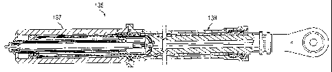
Figure 5 is a detailed cross-sectional view of another embodiment of a triplex
tandem actuator, and Figures 6A and 6B are enlarged, detailed, cross-sectional
views of the actuator of Figure 5.
Figure 5 shows a triplex tandem actuator 135 that has a similar configuration
to actuator 57, which is described above. Actuator 135 comprises a dual
concentric
cylinder configuration in an armored section 137 and a single cylinder
configuration
CA 02650292 2008-10-23
-5-
WO 2008/057142 PCT/US2007/011233
in an unarmored section 139. Figure 6A is an enlarged view of unarmored
section
139, and Figure 6B is an enlarged view of unarmored section 137.
Unarmored section 139 has an unarmored outer wall 141 that forms a single
cylinder actuator for moving ram 143. An extend port 145 extends through outer
wall
141 and communicates with annular fluid volume 147, and a retract port 149
extends
through outer wall 141 and communicates with annular fluid volume 151. In a
similar
manner to that described above for actuator 57, pressure in fluid volume 147
acts on
the corresponding surface of a frangible piston 153 to extend ram 143, and
pressure
in fluid volume 151 acts on the opposite surface of piston 153 to retract ram
143. A
frangible nut and gland seal assembly 155 is used to seal the end of fluid
volume
151 opposite piston 153. A leakage vent 157 is provided in ram 143 to allow
for
venting of fluid that has leaked from the hydraulic system in section 139.
Also, a
sensing port 159 is provided in outer wall 141 for allowing sensing of fluid
leakage
indicative of a damaged gland seal in assembly 155. A triplex linear variable
differential transformer 161 is provided for measuring the amount of
displacement of
ram 143 during operation of actuator 135.
Use of sensing port 159 allows for protection of the hydraulic system powering
section 139. If flow to port 159 (indicating a damaged gland seal assembly
155) is
detected, a flight control computer can configure a manifold (not shown)
feeding
section 139 into a bypass/shutoff configuration to isolate the leak. This
keeps
section 139 from depleting the fluid in the system following damage to gland
seal
assembly 155 and isolates the leak at its source.
Armored section 137 has an armored outer wall 163 that forms a dual
concentric cylinder actuator for moving ram 143. An extend port 165 extends
through outer wall 163 and communicates with annular fluid volume 167, and a
retract port 169 extends through outer wall 163 and communicates with annular
fluid
volume 171. A valve member 173 is located within a skirt portion 175 of ram
143,
and an extend port 177 and a retract port 179 extend through valve member 173.
Valve member 173 is attached to outer wall 163 and does not move with ram 143.
Extend port 177 communicates with fluid volume 181, and retract port 179
communicates with annular fluid volume 183. In a similar manner to that
described
CA 02650292 2008-10-23
-6-
WO 2008/057142 PCT/US2007/011233
above for actuator 57, pressure in fluid volume 167 acts on the corresponding
surface of a piston 185 to extend ram 143, and pressure in fluid volume 171
acts on
an opposite surface of piston 185 to retract ram 143. Likewise, pressure in
fluid
volume 181 acts on inner surface 187 of ram 143 to extend ram 143, and
pressure in
fluid volume 183 acts on a corresponding surface of piston 185 to retract ram
143. A
leakage vent 189 is provided near the interface of section 137, 139 to allow
for
venting of fluid that has leaked from either or both hydraulic systems in
section 137.
In the preferred embodiment, the size and weight of the triplex tandem
actuator cylinder assembly is only slightly more that a similar dual tandem
actuator.
The required large ram diameter creates the space required for the third
cylinder
within the ram. Because the V-22 and many new aircraft will be using hydraulic
systems operating in the range of 5,000 psi, very little effective piston area
is
required to produce desired cylinder operation. The only significant weight
difference between a dual tandem actuator and the triplex tandem actuator is
the
addition of a third control manifold to operate the third cylinder, though
this weight
gain is balanced by the elimination of switching and isolation valves.
Whether dual or triplex in configuration, each actuator cylinder is to be
sized
by the load required for safe operation on one operating cylinder. Because the
armor of the armored section protects two systems, damage to the unarmored
section does not significantly degrade the flight envelope.
The triplex tandem actuator provides for several advantages, including: 1)
providing critical flight control actuation for military aircraft requiring
ballistic
protection; 2) providing increased reliability with no significant envelope or
weight
impact; and 3) providing ballistic protection with no significant envelope or
weight
impact.
This description includes reference to illustrative embodiments, but it is not
intended to be construed in a limiting sense. Various modifications and
combinations of the illustrative embodiments, as well as other embodiments,
will be
apparent to persons skilled in the art upon reference to the description.