Note : Les descriptions sont présentées dans la langue officielle dans laquelle elles ont été soumises.
CA 02650633 2008-10-27
WO 2007/142858 PCT/US2007/012401
MULTI INPUT MULTI OUTPUT (MIMO) ORTHOGONAL FREQUENCY DIVISION
MULTIPLE ACCESS (OFDMA) COMMUNICATION SYSTEM
BACKGROUND
FIELD OF THE INVENTION
[001] Embodiments of the invention relate to the field of communication, and
more
specifically, to MIMO OFDMA communication systems.
DESCRIPTION OF RELATED ART.
[002] MIMO OFDMA systems are becoming popular as a key technology for the next
generation of wired and wireless or mobile communications. The Institute of
Electrical and
Electronics Engineers (IEEE) has provided several standards supporting air
interface for
fixed and mobile broadband wireless access (BWA) systems using MIMO OFDMA such
as
the IEEE 802.16e for mobile BWA systems.
[0031 One of the challenges facing MIMO OFDMA systems design is transmitter
diversity. Existing techniques to provide transmitter diversity has a number
of drawbacks.
One technique uses a space time coding (STC) scheme. The STC scheme takes
advantage
of space and temporal diversities as well as coding gain. This technique
suffers
performance degradation in no multi-path channel such as Additive White
Gaussian Noise
(AWGN) channel, requires a special standard supporting STC scheme, and may
limit
maximum service range. Another technique uses an equal power joint maximum
ratio
combining method for a beam-forming based system. This technique is complex,
requiring
complex solutions for weight vectors and complex procedure for calibration.
Many other
techniques have been proposed but these techniques requires complex processes
such as
time domain processing, interactive processing, hand-shaking or collaboration
between the
base station (BS) and the mobile station (MS).
I
CA 02650633 2011-08-11
74769-2209
SUMMARY
According to an aspect of the invention, there is provided an apparatus
comprising: a plurality of signal processing units to process signals received
from a
plurality of antennae, the signal processor units being controlled by
operational mode
control signals, the operational mode control signals selecting one of a
plurality of
antenna paths associated with the plurality of antennae; a channel estimator
to
estimate channel responses using the processed signals under control of the
operation mode control signals; an equalizer and combiner coupled to the
channel
estimator to generate an equalized and combined signal using the processed
signals
and the estimated channel responses; and a Carrier to Interference Noise Ratio
(CINR) estimator coupled to the equalizer and combiner to estimate CINR from
the
equalized and combined signal, the estimated CINR being used to generate the
operational mode control signals.
According to another aspect of the invention, there is provided an
apparatus comprising: a sub-carrier allocation controller to generate sub-
carrier
allocation signals using an allocation base; a channel status information
(CSI) and
multiple input multiple output (MIMO) controller coupled to the sub-carrier
allocation
controller to generate sub-carrier CSI signals and operational mode control
signals
using the sub-carrier allocation signals, estimated channel responses provided
by a
channel estimator, and an estimated Carrier to Interference Noise Ratio (CINR)
provided by an CINR estimator, the operational mode control signals selecting
one of
a plurality of antenna paths associated with a plurality of antennae; and a
transmitter
diversity processor coupled to the CSI and MIMO controller to generate
transmitter
diversity signals as a function of at least a mapped signal Mk, the sub-
carrier CSI
signals, and the operational mode control signals, wherein k = -N/2, ... , N/2
-1 and N
is a positive integer.
According to yet another aspect of the invention, there is provided a
method comprising: processing signals received from a plurality of antennae
under
control by operational mode control signals, the operational mode control
signals
2
CA 02650633 2011-08-11
74769-2209
selecting one of a plurality of antenna paths associated with the plurality of
antennae;
estimating channel responses using the processed signals under control of the
operation mode control signals; generating an equalized and combined signal
using
the processed signals and the estimated channel responses; and estimating
Carrier to
Interference Noise Ratio (CINR) from the equalized and combined signal, the
estimated CINR being used to generate the operational mode control signals.
According to still another aspect of the invention, there is provided a
method comprising: generating sub-carrier allocation signals using an
allocation base;
generating sub-carrier channel status information (CSI) signals and
operational mode
control signals using the sub-carrier allocation signals, estimated channel
responses
provided by a channel estimator, and an estimated Carrier to Interference
Noise Ratio
(CINR) provided by an CINR estimator, the operational mode control signals
selecting
one of a plurality of antenna paths associated with a plurality of antennae;
and
generating transmitter diversity signals as a function of at least a mapped
signal Mk,
the sub-carrier CSI signals, and the operational mode control signals, wherein
k = -N/2,
N/2 -1 and N is a positive integer.
According to a further aspect of the invention, there is provided a system
comprising: a plurality of antennae; a transmitter processing unit coupled to
the
antennae to generate radio-frequency (RF) transmit signals; and a receiver
processing
unit coupled to the antennae, the receiver processing unit comprising: a
plurality of
receive signal processing units to process the RF receive signals, the signal
processor
units being controlled by operational mode control signals, the operational
mode
control signals selecting one of a plurality of antenna paths associated with
the plurality
of antennae, a channel estimator to estimate channel responses using the
processed
signals under control of the operation mode control signals, an equalizer and
combiner
coupled to the channel estimator to generate an equalized and combined signal
using
the processed signals and the estimated channel responses, and a Carrier to
Interference Noise Ratio (CINR) estimator coupled to the equalizer and
combiner to
estimate CINR from the equalized and combined signal, the estimated CINR being
used to generate the operational mode control signals.
2a
CA 02650633 2011-08-11
74769-2209
BRIEF DESCRIPTION OF THE DRAWINGS
[004] Embodiments of invention may best be understood by referring to the
following
description and accompanying drawings that are used to illustrate embodiments
of the
invention. In the drawings:
[005] Figure 1 is a diagram illustrating a system in which one embodiment of
the
invention can be practiced.
[006] Figure 2 is a diagram illustrating a 2x2 MTMO OFDMA system according to
one
embodiment of the invention.
[007] Figure 3 is a diagram illustrating a communication unit according to one
embodiment of the invention.
[008] Figure 4 is a diagram illustrating a receiver processing unit according
to one
embodiment of the invention.
[009] Figure 5 is a diagram illustrating a receive signal processing unit
according to one
embodiment of the invention.
[0010] Figure 6 is a diagram illustrating a transmitter processing unit
according to one
embodiment of the invention.
[0011] Figure 7 is a diagram illustrating an UL allocation according to one
embodiment of
the invention.
[0012] Figure 8 is a diagram illustrating a CSI and MIMO controller according
to one
embodiment of the invention.
[0013] Figure 9 is a diagram illustrating a transmit signal processing unit
according to one
embodiment of the invention.
2b
CA 02650633 2008-10-27
WO 2007/142858 PCT/US2007/012401
DESCRIPTION
[0014] An embodiment of the present invention is a technique to process
signals in a
communication system. In one embodiment, a plurality of signal processing
units processes
signals received from a plurality of antennae. The signal processor units are
controlled by
operational mode control signals. A channel estimator estimates channel
responses using
the processed signals according to an operational mode. An equalizer and
combiner
generates an equalized and combined signal using the received signals and the
estimated
channel responses. A Carrier-to-Interference Noise Ratio (CINR) estimator
estimates CINR
from the equalized and combined signal. The estimated CINR is used to generate
the
operational mode control signals. In another embodiment, a sub-carrier
allocation controller
generates sub-carrier allocation signals using an allocation base. A channel
status
information (CSI) and multiple input multiple output (MIMO) controller
generates sub-
carrier CSI signals and operational mode control signals using the sub-carrier
allocation
signals, estimated channel responses provided by a channel estimator, and an
estimated
CINR provided by an CINR estimator. The operational mode control signals
select one of a
plurality of antenna paths associated with a plurality of antennae. A
transmitter diversity
processor generates transmitter diversity signals as a function of at least a
mapped signal
Mk, the sub-carrier CSI signals, and the operational mode control signals.
[0015] In the following description, numerous specific details are set forth.
However, it is
understood that embodiments of the invention may be practiced without these
specific
details. In other instances, well-known circuits, structures, and techniques
have not been
shown to avoid obscuring the understanding of this description.
[0016] One embodiment of the invention may be described as a process, which is
usually
depicted as a flowchart, a flow diagram, a structure diagram, or a block
diagram. Although
a flowchart may describe the operations as a sequential process, many of the
operations can
be performed in parallel or concurrently. A loop or iterations in a flowchart
may be
described by a single iteration. It is understood that a loop index or loop
indices or counter
or counters are maintained to update the associated counters or pointers. In
addition, the
order of the operations may be re-arranged. A process terminates when its
operations are
completed. A process may correspond to a method, a program, a procedure, etc.
A block
diagram may contain blocks or modules that describe an element, an item, a
component, a
device, a unit, a subunit, a structure, a method, a process, a function, an
operation, a
3
CA 02650633 2008-10-27
WO 2007/142858 PCT/US2007/012401
functionality, or a task, etc. A functionality or an operation may be
performed
automatically or manually.
[0017] An embodiment of the invention includes a transmitter processing unit
and a
receiver processing unit for wired and wireless communications based on MEMO
OFDMA
techniques. The receiver processing unit provides estimates of the channel
responses and
CINR to the transmitter processing unit. The transmitter processing unit
provides
transmitter diversity by selecting a transmitter antenna path using the
estimated channel
responses and CINR. Transmitter diversity is achieved by selecting the
transmitter antenna
path which has a better CSI than other transmitter antenna paths fora given
bundle. A
bundle is a set of sub-carrier indices. The technique has a number of
advantages including
simple architecture, good performance, reduced power consumption, and does not
require
special standard specifications.
[0015] Figure I is a diagram illustrating a system 100 in which one embodiment
of the
invention can be practiced, The system 100 includes a base station (BS) 110
and a number
of mobile stations. For illustrative purposes, only two mobile stations 120
and 130 are
shown. As is known by one skilled in the art, any number of mobile stations
may be used.
[0019] The base station 110 has a number of antennae 115o to 1151.1. The
mobile station
(MS) 120 has a number of antennae 1250 to 1251.1. The MS 130 has a number of
antennae
1350 to 135;,x_1. I, L, and M are any positive integers. The MS 120 or 130
represents any
mobile unit or sub-system such as cellular phones, mobile personal digital
assistant (PDA),
mobile hand-held devices or computers. In one embodiment, the BS 110 and the
MS's 120
and 130 are compatible with a MIMO OFDMA standard, such as the IEEE 802.16e.
[0020] The MS 120 includes a user's interface 140, an input entry device 145,
a display
element 150, a communication unit 160, and a controller 170. The user's
interface 140
provides interface to the user. It may include graphics user's interface
(GUI), menu, icons,
etc. The input entry device 145 may include any input entry devices such as
keyboard,
pointing device (e.g., stylus), mouse, etc. to allow the user to enter data or
commands. The
display element 150 provides a display. It may be any type of display suitable
for mobile
devices such as thin-film transistor (TFT) liquid crystal display (LCD), color
super-twist
nematic (CSTN), double-layer super-twist nematic (DSTN), high-performance
addressing
(HPA), or any other active or passive-matrix displays. The communication unit
160
receives and transmits data via the antennae 1250 to 125L-I. The communication
unit 160
provides transmitter diversity and selects an antenna path from a number of
antenna paths
4
CA 02650633 2008-10-27
WO 2007/142858 PCT/US2007/012401
using estimates of channel responses and CINR. The controller 170 controls the
operation
of the MS 120 including processing receive and transmit data, controlling the
input entry
device 145 and/or the display element 150, and performing other house-keeping
tasks. It
may include a processor, a digital signal processor, a micro-controller, etc.
and associated
memory and peripheral devices,
[0021] Figure 2 is a diagram illustrating a 2x2 MIMO OFDMA system 200
according to
one embodiment of the invention, The system 200 includes the BS 110 and the MS
120.
The system 200 is an illustrative system where each of the BS 110 and MS 120
has two
antennae. It is contemplated that each of the BS 110 and MS 120 may have any
number of
antennae as shown in Figure 1.
[0022] The BS 110 has two antennae 1150 and 115, corresponding to BS antennae
0 and 1,
respectively. The MS 120 has two antennae 1250 and 125, corresponding MS
antennae 0
and 1, respectively. The MS 120 contains the communication unit 160 as shown
in Figure
1. For clarity, not all of the elements or components are shown.
[0023] The BS 110 may activate both antennae 1150 and 1151 or one of them
depending on
a BS operational mode. Similarly, the MS 120 may activate both antennae 1250
and 1251 or
one of them depending on a MS operational mode. It depends on the system
operational
mode of standard base or non-standard base to decide how many activated
antennae to be
used in either the BS 110 or the MS 120.
[0024] The communication between the BS 110 and the MS 120 may be carried out
through
four channels: H0o between antennae 1150 and 1250, H01 between antennae 1150
and 1251,
HID between antennae 115, and 1250, and H11 between antennae 1151 and 1251.
Any
configuration of the state of the antennae 1150,115,,1250 and 125, may be
possible.
[0025] Table 1 shows all the possible system configurations according to the
state of the
antennae 1150,115,,1250 and 1251. The state of the antennae may be active or
inactive. An
active state corresponds to the state where the antenna is actively receiving
or transmitting
signals. An inactive state corresponds to the state where the antenna is not
actively
receiving or transmitting signals or in power-down or power-saving mode.
1150 1151 1250 1251 MIMO Channels
system available
active active active active 2x2 H00, H01, H10, H11
active active active inactive 2x1 H00, H10
active active inactive active 2x1 Hal, Htt
active inactive active active 1x2 H00, H01
CA 02650633 2008-10-27
WO 2007/142858 PCT/US2007/012401
inactive active active active 1x2 H,o, H>1
active inactive active inactive 1xi H0o
active inactive inactive active 1x1 Ho,
inactive active active inactive 1xl H,o
inactive active inactive active 1x 1 Hi l
Table 1
[0026] Figure 3 is a diagram illustrating the communication unit 160 shown in
Figure 1
according to one embodiment of the invention. The communication unit 160
includes a
receiver processing unit 310, a transmitter processing unit 320, and a medium
access control
(MAC) processor 330. The designation of the terms "receiver" and "transmitter"
is mainly
for clarity. An element in the receiver processing unit 310 may belong to the
transmitter
processing unit 320, or vice versa.
[0027] The receiver processing unit 310 processes the RF signals received from
the
antennae 1250 and 125, via a downlink (DL) reception path. It provides a
decoded signal or
a base-band data stream to the MAC processor 330. It also provides a CINR
estimate and
estimated channel responses to the transmitter processing unit 320.
[0028] The transmitter processing unit 320 receives the transmit data,
transmitter diversity
mode and an allocation base from the MAC processor 330 to generate the RF
transmit
signals to the antennae 1250 and 125E via an uplink (UL) transmission path,
The transmitter
processing unit 320 provides operational mode control signals to select one of
the antennae
for transmission via a transmitter diversity technique.
[0029] The MAC processor 330 performs data processing on the decoded signal
from the
receiver processing unit 310 and the transmit data to be sent to the
transmitter processing
unit 320. It also provides a transmitter diversity mode to select the mode for
transmitter
diversity. In addition, it also provides an allocation base for the
transmitter processing unit
320.
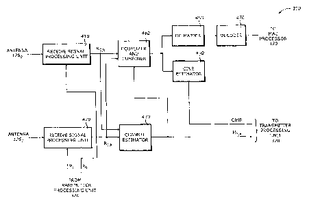
[0030] Figure 4 is a diagram illustrating the receiver processing unit 310
shown in Figure 3
according to one embodiment of the invention. The receiver processing unit 310
includes
receive signal processing units 410 and 420, a channel estimator 430, an
equalizer and
combiner 440, a CT_NR estimator 450, a de-mapper 460, and a decoder 470.
[0031] The signal processing units 410 and 420 are connected to the antennae
125o and
1251, respectively. They define the antenna paths associated with the antennae
1250 and
1251. Each of the signal processing units 410 and 420 processes the signal
received from the
6
CA 02650633 2008-10-27
WO 2007/142858 PCT/US2007/012401
corresponding antenna under control of operational mode control signals Po and
P1 provided
by the transmitter processing unit 320. The operational mode control signals
may set the
antennae 1250 and 125, and the signal processing units 410 and 420 in active
or inactive
mode in any combination. In active mode, the antennae 125() and 125, and the
signal
processing units 410 and 420 are in a normal operational state. In inactive
mode, the
antennae 1250 and 125, and the signal processing units 410 and 420 may be in
power-save
or power-down state. The signal processing units 410 and 420 generate
frequency domain
signals RO,k and R1,k, respectively.
[00321 The channel estimator 430 estimates channel responses using the
processed signals
R0 k and R,,k from the signal processing units 410 and 420 according to an
operational
mode. The channel estimator computes the estimated channel responses according
to the
following equation:
H;l,k = estimate of Hij if Hij is defined, (1)
0 otherwise
where Hij is an estimate of the channel ij associated with antenna i and
antenna j; i,j = 0,1,
and k = -N/2, . . ., N/2 -1. N is a positive integer that corresponds to the
total number of
subcarrier points used in the signal processing units 410 and 420.
[0033] For example, suppose a system configuration is a 1x2 MIMO system and
the MI1MO
operational mode corresponds to active BS antenna 1150, inactive BS antenna 1
l.51i active
MS antenna 1250, and active MS antenna 1251. As shown in Table 1, this
operational mode
corresponds to two available channels H00 and H01. In this case, from equation
(1) above,
the estimated channel responses Ho0,k and Hol,k may have certain valid values,
whereas the
estimated channel responses Hlo,k and Hil.k have zero values.
[0034] The equalizer and combiner 440 generates an equalized and combined
signal using
the processed signals RO,k and R1,k and the estimated channel responses
H,j,k's provided by
the channel estimator 430. It is also controlled by the MIMO operational mode.
For
example, in case of 2x2 MIMO, the equalizer and combiner 440 uses the
estimated channel
responses Hook, Hol,k, H1O,k and H, l,k to equalize and combine the Ro,k and
R,,k signals. In
case of 1xI MIMO, the equalizer and combiner 440 uses only the estimated
channel
response Hook to simply equalize the Ro,k.
[00351 The CINR estimator 450 estimates the CINR from the equalized and
combined
signal. The estimated CINR is used to generate the operational mode control
signals in the
transmitter processing unit 320.
7
CA 02650633 2008-10-27
WO 2007/142858 PCT/US2007/012401
[0036] The de-mapper 460 de-maps the equalized and combined signal. The
decoder 470
decodes the de-mapped signal. The decoded signal is then processed by the MAC
processor
330.
[0037] Figure 5 is a diagram illustrating the receive signal processing unit
4101420 shown
in Figure 4 according to one embodiment of the invention. The receive signal
processing
unit 410/420 includes a RF front end processor 510, a guard remover 520, and a
frequency
domain processor 530.
[0038] The RF front end processor 510 performs RF functions on the
corresponding
received RF signal. The RF functions may include RF signal conditioning,
filtering, down-
conversion, and analog-to-digital conversion. The guard remover 520 removes a
guard
interval from the received signal.
[0039] The frequency domain processor 530 converts the received signal to a
frequency
domain signal having N data points. The frequency domain signal corresponds to
the
processed signal R;,k where i = 0,1. They are sent to the equalizer and
combiner 430 and the
channel estimator 440. In one embodiment, the frequency domain processor 530
computes
the Fast Fourier Transform (FFT) of the corresponding received data stream
where the FFT
size is N.
[0040] Figure 6 is a diagram illustrating the transmitter processing unit 320
shown in Figure
3 according to one embodiment of the invention. The transmitter processing
unit 320
includes a sub-carrier allocation controller 610, an encoder 620, a mapper
630, a channel
status information (CSI) and multiple input multiple output (MIMO) controller
640, a
transmit diversity processor 650, and transmit signal processing units 660 and
670.
[0041] The sub-carrier allocation controller 610 generates sub-carrier
allocation signals
using the allocation base from the MAC processor 330, The sub-carrier
allocation signals
include an allocation information signal Salloc and a diversity unit, Bunit.
The allocation
information signal contains information on the diversity unit. The diversity
unit Bunit is
one of a burst, a slot, and an allocation unit. The allocation base is
discussed further in
Figure 7.
[0042) The encoder 620 encodes transmit data provided by the MAC processor
330. The
mapper 630 maps and modulates the encoded transmit data for a sub-carrier
index based on
the allocation information signal to provide the mapped signal Mk, according
to the
following equation:
8
CA 02650633 2008-10-27
WO 2007/142858 PCT/US2007/012401
Mapping & Modulation, if k is allocated
Mk = (2)
0, Otherwise
where k = -N/2,. , N/2 -1
[0043] For a 2x2 MIMO, the CSI and MIMO controller 640 generates sub-carrier
CSI
signals CO,k and C1,k and operational mode control signals Po and P,
corresponding the
antennae 1250 and 1251, respectively, using the sub-carrier allocation
signals, the estimated
channel responses provided by the channel estimator 440, and the estimated
CINR provided
by the CINR estimator 470. The operational mode control signals PO and P,
select one of
the antenna paths associated with the antennae 125o and 1251. The antenna
paths
correspond to the transmit signal processing units 660 and 670. The
operational mode
control signals Po and P1 may assume two values: active or inactive, to
indicate whether the
antennae 1250 or 1251 is active or inactive. The details of the computation of
the sub-carrier
CSI signals C0,4 and C1,k and operational mode control signals PO and P, are
shown in Figure
8.
[0044] The transmitter diversity processor 650 generates transmitter diversity
signals as a
function of at least the mapped signal Mk, the sub-carrier CSI signals, and
the operational
mode control signals. The transmitter diversity processor 650 generates the
transmitter
diversity signals according to a transmitter diversity mode corresponding to
whether phase
alignment is used. The transmitter diversity mode is provided by the MAC
processor 330.
[0045] For a 2x2 MTMO, the transmitter diversity processor 650 generates a
first transmitter
diversity signal Tok and a second transmitter diversity signal T1,k
corresponding to the first
and second antenna paths, respectively, according to the transmitter diversity
mode (TxD).
When the TxD indicates that the phase alignment is used, To,k and TI,k are
determined
according to the following equations:
Mk x
IHIIO,kl H o'k if (P Active and P, Inactive)
k=-N12,...,N12-1
7o,k = M. X H 0'k elseif (C k >_ C,.k) and (Po Active and P Active) , a = 0 if
BS use ant 0 (3a
IHiO k I a = I if BS use ant 1
0 else
9 (31
CA 02650633 2008-10-27
WO 2007/142858 PCT/US2007/012401
M, x H~ if (Po Inactive and P Active)
IH,,I,kl k N12,..,, N/2-t
TI', M x elsei C < C,,,,) and (P Active and P Active) a = 0 if BS use ant 0
a=I if BS =use ant I
0 else
where k = -N/2, ..., N/2 -1; a = 0 if the first antenna 1250 is used and a =1
if the
second antenna 1251 is used. H*y,k indicate the complex conjugate of H;j,k and
jH;J,k' is the
magnitude of Hij,k. The H;j,k's are determined according to equation (1)
above.
[0046] When the TxD indicates that the phase alignment is not used, To,k and
Tl,k are
determined according to the following equations:
Mk if' (Po Active and P, Inactive)
TO,k = Mk elseif (CQ,k >: C,,k) and (Po Active and P Active) , k = -N / 2,...,
N / 2 - I (4a)
0 else
Mk if (Po Inactive and P Active)
T,.k = M k elseif (Co k < C,,k) and (Po Active and P Active) , k = -N / 2,
..., N / 2 -1 (4b)
0 else
where k = -N/2, ..., N/2 - I.
[0047] The transmitter signal processing units 660 and 670 correspond to the
antenna paths
for transmission. The transmitter signal processing unit 660 is associated
with the antenna
1250 and processes a first transmitter diversity signal T0,k of the
transmitter diversity signals
using the first operational mode control signal PO. The transmitter signal
processing unit
670 is associated with the antenna 1251 and processes a second transmitter
diversity signal
T1,k of the transmitter diversity signals using the second operational mode
control signal P1,
[0048] Figure 7 is a diagram illustrating an UL allocation according to one
embodiment of
the invention. The UL allocation indicates the allocation base used in the
system.
[0049] According to the IEEE 802.16e standard, a frame structure may have a
number of
frames, The n-th frame consists of a DL sub-frame, an UL sub-frame, transmit-
to-receive
transition gap (TTG), and receive-to-transmit transition gap (RTG). The DL sub-
frame
CA 02650633 2008-10-27
WO 2007/142858 PCT/US2007/012401
consists of a preamble, a frame control header (FCH), a DL map, and several DL
bursts.
The UL sub-frame consists of ranging sub-channels and several UL bursts.
[0050] The DL and UL bursts are defined in two dimensional plane defined by a
sub-carrier
axis (or sub-channel axis) and an OFDMA symbol axis, respectively. The i-th UL
burst 710
consists of one or more than one slot 720j's. Each slot 720 consists of
several Allocation
Units 730k's which have all same structure. There are three different UL
Allocation Units
as basic allocation units: a partial usage of the sub-channels (PUSC) 740, an
optional PUSC
750, and an AMC allocation 760.
[0051] The PUSC Allocation Unit is composed of 4 sub-carriers and 3 symbols.
There are 4
pilot sub-carriers P's and 8 data sub-carriers in a Tile (4x3). In UL PUSC
permutation
method, a slot is constructed from 6 Tiles(4x3). The optional PUSC Allocation
Unit is
composed of 3 sub-carriers and 3 symbols. There are I pilot sub-carrier P and
8 data sub-
carriers in a Tile (3x3). In UL optional PUSC permutation method, a slot is
constructed
from 6 Tiles (3x3). The UL AMC Allocation Unit is composed of 9 sub-carriers
and I
symbol. There are 1 pilot sub-carder P and 8 data sub-carriers in a Bin (9x1),
In the UL
AMC permutation method, a slot is constructed from 1x6 (sub-carrier axis x
symbol axis)
Bins (9x1)s, 2x3 Bins (9x1), 3x2 Bins (9x1), or consecutive 6 Bins (9x 1)
along the
allocation region.
[0052] Figure 8 is a diagram illustrating the CSI and MIMO controller 640
shown in Figure
6 according to one embodiment of the invention. The CSI and MIMO controller
640
includes a bundle CSI generator 810, a sub-carrier CS1 channel generator 820,
an overal I
CSI generator 830, and an operational mode controller 840.
[0053] The bundle CSI generator 810 generates bundle CSI signals based on a
bundle b
using the estimated channel responses. The bundle CSI generator 810 generates
a first
bundle CSI signal BCO,b and a second bundle CSI signal BCr,b corresponding to
first and
second antenna paths associated with first and second antennae, respectively,
according to
the following equations:
BCo'b = 1 (IHoo,xbtrrl2 +1Hia.xbtr)12), b=1,..., B, xb(1)cXb (5a)
L r=1
BC,,b = ~(~Hoi,.rbtrr~2 f Hj 1.abt1r12 ), b = 1, ..., B, xG (1) C X. (Sb)
L ,.,
(0054] where Hoq,,b(J), Hot,Xb(r), Hro,Xb(l), and '11b(1) correspond to the
estimated channel
responses, and Xb = {xb(1), ..., xb(1), ..., xb(L)) is a set of sub-carrier
indices, xb(/) is the /-th
11
CA 02650633 2008-10-27
WO 2007/142858 PCT/US2007/012401
element of the b-th bundle and has an integer value representing a sub-carrier
index greater
than or equal to -N/2 and less than N/2, N being a positive integer; L is
number of elements
of the bundle b; and B represents a total number of bundles and is provided by
the sub-
carrier allocation signals.
[0055] The sub-carrier CSI generator 820 generates the sub-carrier CSI signals
Co,k and Ci,k
using the bundle CSI signals. The sub-carrier CSI generator 820 generates a
first sub-
carrier CSI signal Co,k and a second sub-carrier CSI signal C),k corresponding
to the first
and second antenna paths, respectively, according to the following equations:
0, initialization
Ca.k= k=-N12,...,N12-1, 1:5bSB (6a)
BCO,G if k c XG,
0, initialization
C,,k = , k = -N 12, ..., N 12 -1, 1 <- b 5 B (6b)
13C1 , if kcXG,
[0056] The overall CSI generator 830 generates overall CSI signals using the
sub-carrier
CSI signals Co,k and CU. The overall CSI generator 830 generates a first
overall CSI signal
PCo and a second overall CSI signal PC1 con'esponding to the first and second
antenna
paths, respectively, according to the following equations:
PCo =ZCO,k, k =-N12,..., N12-1 (7a)
k
PC,=EC,,k, k=-N12,...,N12-1 (7b)
k
[0057] The operational mode controller 840 generates the operational mode
control signals
using the overall CSI signals and a threshold THRCWR, The threshold TI-3RCINR
may be
selected according to the channel state or the type of modulation. The
operational mode
generator 840 generates a first operational mode signal Pty and a second
operational mode
signal P, corresponding to the first and second antenna paths, respectively,
according to the
following equations:
Active, if CINR <THRch,R
Po = Active, elseif CINR > THRc,NR and PCp > PC1 (8a)
Inactive, elseif CINR > THRC,NR and PC, < PC1
(8b)
12
CA 02650633 2008-10-27
WO 2007/142858 PCT/US2007/012401
Active, if CINR <THRcxn
P = Inactive, elseif CINR >_ THRcJ,,,R and PCo >_ PC,
Active, elseif CINR > THRcINR and PC0 , < PCs
where CINR is the estimated CINR provided by the CINR estimator 470.
[0055] The operational mode control signals PO and P1 may be used to adjust
the number of
antenna paths using the estimated CINR and CSI. Consequently, the power
consumption of
the communication unit 160 may be reduced or minimized. This is especially
useful for
hand-held mobile wireless devices.
[0059] Figure 9 is a diagram illustrating the transmit signal processing unit
660/670
according to one embodiment of the invention. The transmit signal processing
unit 660/670
includes an inverse frequency domain processor 910, a guard inserter 920, and
a RF front
end processor 930.
[0060] The inverse frequency domain processor 910 converts one of the first
and second
transmitter diversity signals to a transmit signal. In one embodiment, the
inverse frequency
domain processor 910 computes the inverse FFT of the transmit diversity signal
using an
inverse FFT size of N. The guard inserter 920 inserts a guard band to the
transmit signal.
[0061] The RF front end processor 930 performs RF functions on the transmit
signal. The
RF functions may include digital-to-analog conversion, RF signal condition,
filtering, and
up-conversion.
(0062) As discussed above, the transmitter diversity scheme used in the
present invention
may be applied to any systems without changing the standard specification
(e.g., IEEE
802.16e). In other words, any receiver conforming to the standard may receive,
de-map,
demodulate,, and decode the transmit signal. In addition, the communication
unit 160 is not
limited to two antennae. The above discussion may be extended to any number of
antennae.
The structure of the communication unit 160 may be modified accordingly.
[0063] Elements of embodiments of the invention may be implemented by
hardware,
firmware, software or any combination thereof. The term hardware generally
refers to an
element having a physical structure such as electronic, electromagnetic,
optical, electro-
optical, mechanical, electro-mechanical parts, components, or devices, etc.
The term
software generally refers to a logical structure, a method, a procedure, a
program, a routine,
a process, an algorithm, a formula, a function, an expression, etc. The term
firmware
13
CA 02650633 2008-10-27
WO 2007/142858 PCT/US2007/012401
generally refers to a logical structure, a method, a procedure, a program, a
routine, a
process, an algorithm, a formula, a function, an expression, etc., that is
implemented or
embodied in a hardware structure (e.g., flash memory). Examples of firmware
may include
microcode, writable control store, micro-programmed structure. When
implemented in
software or firmware, the elements of an embodiment of the present invention
are
essentially the code segments to perform the necessary tasks. The
software/firmware may
include the actual code to carry out the operations described in one
embodiment of the
invention, or code that emulates or simulates the operations. The program or
code segments
can be stored in a processor or machine accessible medium or transmitted by a
computer
data signal embodied in a carrier wave, or a signal modulated by a carrier,
over a
transmission medium. The "processor readable or accessible medium" or "machine
readable or accessible medium" may include any medium that can store,
transmit, or
transfer information. Examples of the processor readable or machine accessible
medium
include an electronic circuit, a semiconductor memory device, a read only
memory (ROM),
a flash memory, an erasable ROM (EROM), an erasable programmable ROM (EPROM),
,a
floppy diskette, a compact disk (CD) ROM, an optical disk, a hard disk, a
fiber optic
medium, a radio frequency (RF) link, etc. The computer data signal may include
any signal
that can propagate over a transmission medium such as electronic network
channels, optical
fibers, air, electromagnetic, RF links, etc. The code segments may be
downloaded via
computer networks such as the Internet, Intranet, etc. The machine accessible
medium may
be embodied in an article of manufacture. The machine accessible medium may
include
data that, when accessed by a machine, cause the machine to perform the
operations
described above. The machine accessible medium may also include program code
embedded therein. The program code may include machine readable code to
perform the
operations described above. The term "data" here refers to any type of
information that is
encoded for machine-readable purposes. Therefore, it may include program,
code, data,
file, etc.
[0064] All or part of an embodiment of the invention may be implemented by
hardware,
software, or firmware, or any combination thereof. The hardware, software, or
firmware
element may have several modules coupled to one another. A hardware module is
coupled
to another module by mechanical, electrical, optical, electromagnetic or any
physical
connections. A software module is coupled to another module by a function,
procedure,
method, subprogram, or subroutine call, a jump, a link, a parameter, variable,
and argument
passing, a function return, etc. A software module is coupled to another
module to receive
14
CA 02650633 2008-10-27
WO 2007/142858 PCT/US2007/012401
variables, parameters, arguments, pointers, etc. and/or to generate or pass
results, updated
variables, pointers, etc. A firmware module is coupled to another module by
any
combination of hardware and software coupling methods above. A hardware,
software, or
firmware module may be coupled to any one of another hardware, software, or
firmware
module. A module may also be a software driver or interface to interact with
the operating
system running on the platform. A module may also be a hardware driver to
configure, set
up, initialize, send and receive data to and from a hardware device. An
apparatus may
include any combination df hardware, software, and firmware modules.
[0065] While the invention has been described in terms of several embodiments,
those of
ordinary skill in the art will recognize that the invention is not limited to
the embodiments
described, but can be practiced with modification and alteration within the
spirit and scope
of the appended claims. The description is thus to be regarded as illustrative
instead of
limiting.