Sélection de la langue

Search

Sommaire du brevet 2652017 

Énoncé de désistement de responsabilité concernant l'information provenant de tiers

Une partie des informations de ce site Web a été fournie par des sources externes. Le gouvernement du Canada n'assume aucune responsabilité concernant la précision, l'actualité ou la fiabilité des informations fournies par les sources externes. Les utilisateurs qui désirent employer cette information devraient consulter directement la source des informations. Le contenu fourni par les sources externes n'est pas assujetti aux exigences sur les langues officielles, la protection des renseignements personnels et l'accessibilité.

Disponibilité de l'Abrégé et des Revendications

L'apparition de différences dans le texte et l'image des Revendications et de l'Abrégé dépend du moment auquel le document est publié. Les textes des Revendications et de l'Abrégé sont affichés :

  • lorsque la demande peut être examinée par le public;
  • lorsque le brevet est émis (délivrance).
(12) Brevet: (11) CA 2652017
(54) Titre français: PLANCHER VIBRANT MODULAIRE
(54) Titre anglais: MODULAR VIBRATORY FLOOR
Statut: Accordé et délivré
Données bibliographiques
Abrégés

Abrégé français

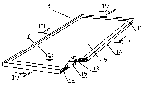
L'invention concerne un plancher vibrant constitué de modules vibrants indépendants pouvant être préfabriqués et strictement contrôlés avant leur mise en place dans des structures de stockage ou de transport de produits vrac. Chaque module vibrant est constitué d'un cadre (14) dans lequel est disposé un matériau de support (12), sur lequel repose une tôle (9) solidaire d'un organe vibrant (10) et d'un raidisseur (19), maintenue en place seulement par une membrane d'étanchéité périphérique (11) et portant éventuellement sur des ressorts de compression (13). Le matériau de remplissage peut comporter des nervures (30) propres à déformer la tôle sous la forme d'ondes transversales (31) sous l'effet du poids du produit stocké. Les modules vibrants ainsi constitués sont étanches à la poussière, ne transmettent pas de vibrations à la structure environnante, et vidangent efficacement tout produit grenu ou pulvérulent de silos, de navires, de wagons de chemin de fer ou de tous autres contenants.


Abrégé anglais

The invention relates to a vibratory floor consisting of independent vibratory modules that can be pre-fabricated and are strictly controlled before being put into place in structures for storage or transport of bulk products. Each vibratory module consists of a frame (14) in which a support material (12) is arranged, on which a metal sheet (9) is mounted, said metal sheet being attached to a vibratory element (10) and a stiffener (19) and held in place only by a peripheral sealing membrane (11), optionally supported by compression springs (13). The filling material can comprise ribs (30) for deforming the metal sheet in the form of transversal waves (31) under the effect of the weight of the stored product. The vibratory modules constructed in this way are dust-tight, do no transmit vibrations to the surrounding structure, and effectively drain any lumpy or powdery product from silos, ships, railroad cars, or other containers.

Revendications

Note : Les revendications sont présentées dans la langue officielle dans laquelle elles ont été soumises.


7
CLAIMS
1. A modular vibratory floor for a walled storage structure (1) supported on
tilted faces (33), consisting of one or more vibratory modules (4),
characterized in that
each module (4) forms a preassembled independent unit on a frame (14), fitted
out with a
supporting material (12) on which a metal sheet (9) attached to a vibratory
member (10)
and to a transverse stiffener (19) rests, the stiffener (19) being housed
inside an empty
space (20) made in the supporting material (12).
2. The modular vibratory floor according to claim 1, characterized in that the
supporting material (12) is a metal or plastic siding sheet with transverse,
round, omega-
shaped or prismatic waves (32).
3. The modular vibratory floor according to claim 1, characterized in that the
supporting material (12) is a heat insulator consisting of material lightened
by inclusion of
air or gas.
4. The modular vibratory floor according to claim 1, characterized in that the
supporting material (12) is a plastic material compound with a cellular
structure of the
honeycomb type.
5. The modular vibratory floor according to claim 1, characterized in that the
supporting material (12) is an assembly of plastic profiles.
6. The modular vibratory floor according to claim 1, characterized in that the
supporting material (12) is a ligneous fiber composite.
7. The modular vibratory floor according to any of claims 2 to 6,
characterized
in that the supporting material (12) includes in an upper portion transverse
ribs (30) with a
predefined gap, on which transverse waves (31) are formed in the metal sheet
(9) by

8
deformation of the metal sheet under the weight of the stored product during
the first
loading operations.
8. The modular vibratory floor according to any of claims 1 to 7,
characterized
in that compression springs (13) are interposed between the metal sheet (9)
and the
supporting material (12) and attached in the supporting material (12).
9. The modular vibratory floor according to any of claims 1 to 8,
characterized
in that the metal sheet (9) is held in place on the frame (14) only by a
connection with a
flexible peripheral sealing membrane (11) attached on the perimeter of the
frame, and
only by bearing upon compression springs (13), the metal sheets of different
modules
further not having any connection between them.
10. The modular vibratory floor according to claim 9, characterized in that
the
profile of the sealing membrane (11) has at one end, a grooved shape (23)
fitted and
adhered onto the perimeter of the metal sheet (9) and at the other end, a
bulge (24) held
by rabbets (27) and the corner irons (21) of the frame (14).
11. The modular vibratory floor according to any of claims 1 to 10,
characterized in that the outer walls (1) are those of a ship, the tilted
faces (33) being the
ballast floor (37) of the ship.
12. The modular vibratory floor according to claim 11, characterized in that
the
tilted faces (33) form a double bottom (41) added to the structure of the
ship.
13. The modular vibratory floor according to any of claims 1 to 12,
characterized in that longitudinal modules (39) allow the number of discharge
apertures
(40) to be reduced.

9
14. The modular vibratory floor according to any of claims 1 to 10,
characterized in that the outer walls (1) are those of a railroad car, the
tilted faces (33)
joining together at their top (34) in the longitudinal axis of the car.

Description

Note : Les descriptions sont présentées dans la langue officielle dans laquelle elles ont été soumises.


CA 02652017 2008-11-12
1
MODULAR VIBRATORY FLOOR
The present invention relates to a universal system for emptying lumpy and
powdery
products by a modular vibratory floor.
The technique of the vibratory floor used for emptying residual heaps in silos
and
ships consists in vibratory metal sheets supported on springs, joined end-to-
end in order to
form crossbars, installed on slopes tilted towards recovery apertures. Each
crossbar is held
in place by anchorings placed in the high portion of the upper sheet. The seal
of the
system is ensured by a membrane, an end of which is attached to the periphery
of each
crossbar, and the other end is held to the ground by metal rabbets. Each
vibratory sheet is
transversely stiffened by a stiffener attached under the metal sheet, and
housed in a
blockout provided for this purpose in the slope. This technique has serious
application and
operational drawbacks. Indeed, as the vibratory metal sheets are firmly
attached end-to-
end in order to form crossbars, the installation should mandatorily be carried
out in situ,
causing long periods of immobilization of the silos and of ships preventing
their
utilization. The in situ installation is carried out at ground level, under
very hard working
conditions, thereby creating difficulties in quality control of the assembly.
On the other
hand, each spring requires that a hole be pierced in the slope concrete, which
entails a
considerable number of piercing operations. Further, the presence of the
stiffeners forces
provision of blockouts during the building of the slopes, most often achieved
by
concreting, which blockouts complicate the application of the concreting, and
which may
not coincide with the final position of the stiffeners. Further, taking into
account the
unavoidable flatness defects of the foundations on which the vibratory floors
are installed,
it is very difficult to guarantee a sufficient seal in order to prevent any
penetration of dust
under the metal sheet, capable of perturbing the operation of the system.
Moreover,
setting the vibratory metal sheets in direct contact with the foundation may
create a cold
wall phenomenon between the metal sheets and the layer of product in contact
with them,
and generate humidity able to degrade the stored product and accelerate
corrosion of the
metal sheets. As for the anchorings set into place in the upper portion of the
crossbars for
preventing them from sliding, they form connections between the vibratory
portions and

CA 02652017 2008-11-12
2
the supporting slope, connections capable of transmitting vibrations to the
whole of the
structure and causing disturbances therein. Further these are wearing parts
requiring
maintenance, and preferential points for dust penetrations. Finally, the use
of flat metal
sheets gives rise to the appearance of parasitic transverse vibratory modes,
not very
favorable to the sought-after flow of the product to be emptied.
The present invention relates to a vibratory floor which overcomes the
disadvantages of prior solutions, notably by allowing vibratory floors to be
prefabricated
as independent vibratory modules, pre-assembled on frames. Consequently, it is
no longer
necessary to provide blockouts in the slopes, the stiffeners finding place
inside the frames.
According to a particular feature of the invention, the metal sheet of each
vibratory
module is only held in place by its peripheral sealing membrane, which
suppresses the
requirement of anchorings, and eliminates any transmission of vibrations to
the
surrounding structure.
In a preferred embodiment of the invention, which per se is not exclusive of
the
latter, the sealing membrane has on one side a grooved shape which will adhere
onto the
edge of the metal sheet, and on the other side a bulge which is maintained on
the edge of
the frame by metal rabbets.
According to another feature of the invention, a supporting material which may
be a
heat insulator is incorporated into the frames, thereby reducing the cold wall
phenomenon
between the metal sheet and the stored product, and easily allowing the
springs to be set
into place and held.
According to another complementary feature of the invention, the supporting
material has ribs or embossments in the upper portion, on which the metal
sheet will
deform by stamping under the load of the stored product, in order to form
transverse
waves.
Other features of a modular vibratory floor, established according to the
invention,
will again appear through the following description of exemplary embodiments,
given as
an indication and by no means as a limitation, with reference to the appended
drawings
wherein:
- Fig. 1 is a schematic plane view of the relevant modular vibratory floor
- Fig. 2 is a transverse sectional view along the line I-I of Fig. 1

CA 02652017 2008-11-12
3
- Fig. 3 is a longitudinal sectional view along the line II-II of Fig. 1
- Fig. 4 is a perspective view of a vibratory module
- Fig. 5 is a transverse sectional view along the line III-III of Fig. 4 of
the unloaded
vibratory module
- Fig. 6 is a longitudinal sectional view, along the line IV-IV of Fig. 4 of
the
unloaded vibratory module
- Fig. 7 is a view at a larger scale illustrating various details of Fig. 6
- Fig. 8 is a view at a larger scale illustrating various details of Fig. 7
- Fig. 9 is another longitudinal sectional view along the line IV-IV of Fig. 4
of the
unloaded vibratory module
- Fig. 10 is a longitudinal sectional view along the line IV-IV of Fig. 4 of
the loaded
vibratory module
- Fig. I 1 is further another longitudinal sectional view along the line IV-IV
of Fig. 4
of the unloaded vibratory module
- Fig. 12 is a plane view of a modular vibratory floor in a railroad car
- Fig. 13 is a transverse sectional view along the line V-V of Fig. 12
- Fig. 14 is another transverse sectional view along the line V-V of Fig. 12
- Fig. 15 is further another transverse sectional view along the line V-V of
Fig. 12
- Fig. 16 is a plane view of a modular vibratory floor in a self-cleaning ship
- Fig. 17 is a transverse sectional view along the line VI-VI of Fig. 16 of a
new ship
- Fig. 18 is a transverse sectional view along the line VI-VI of Fig. 16 of a
transformed ship.
In the exemplary embodiment illustrated in Fig. 1, the storage structure
includes a
wall 1 and slopes 2, made on either side of a discharge channel 3. Vibratory
modules 4
with a rectangular shape, modules 5 with a trapezoidal shape or modules 6 of a
triangular
shape, rest on the slopes transversely.
Advantageously, ventilation ducts 7, required for ventilation of certain
stored
products, may be interposed between the vibratory modules. Alternatively, a
cable path 8
may be positioned between the modules, or the latter may be directly
juxtaposed.
As this is seen in Fig. 4 from a perspective view, and in the sections of
Figs. 5 and 6,
a vibratory module includes a metal sheet 9, a vibratory member 10, a sealing
membrane

CA 02652017 2008-11-12
4
11, a supporting material 12, compression springs 13, preassembled on a frame
14, and
this regardless of the shape of the module.
Referring more particularly to the detail of Fig. 7, it is seen that on the
metal sheet 9,
the vibratory member 10 includes a vibrator 15 of the electric or other type,
resting on a
counter-plate 16, a supporting plate 17 with an edge on which a hood 18 is
attached by
bolting or any other similar means. A stiffener 19 positioned transversely
under the metal
sheet 9 in a space 20 made in the supporting material, is bolted to the
vibrator 15 through
the metal sheet 9, the counter-plate 16 and the supporting plate 17.
Alternatively, the
vibrator 15 may be positioned underneath the metal sheet 9, in which case
bolting hems in
the vibrator 15, the stiffener 19, the metal sheet 9, and the counter-plate
16.
According to the invention, the frame 14 consists of corner irons 21, the
vertical
wing of which has in the upper portion a tilted portion 22, assembled at their
ends by
welding or any other means, on the horizontal wing of which the supporting
material 12
rests, itself consisting of a lightweight material of the type: extruded
polystyrene,
polyurethane foam, aluminum foam, honeycomb plastic or other structure,
openworked
wood or any other material, capable of withstanding compression forces induced
by the
stored product without being deformed.
According to another feature of the invention, the profile of the sealing
membrane
11 illustrated at a larger scale on the detail of Fig. 8, includes at one end,
a grooved shape
23 continuously fitted onto the edge of the metal sheet 9 and held there by
bonding,
welding, vulcanization, screwing, riveting, or any other means. The profile of
the
membrane 11 has at its other end a bulge 24, and a flexible portion 25 between
the
grooved portion 23 and the bulge 24. The portions 23, 24 and 25 of the profile
of the
membrane 11 may be made in the same material by molding, casting, extruding or
welding, or in different materials bonded or welded together or obtained by bi-
extrusion
or multi-extrusion.
In a preferred embodiment of the invention, but which per se is not exclusive
of the
latter, the triangular shaped bulge 24 is held in place by jamming it between
the tilted
portion 22 of the corner iron 21 and the other portion 26 forming a reflex
angle of a metal
rabbet 27 having a lower horizontal wing 28 surrounding the horizontal wing of
the

CA 02652017 2008-11-12
corner iron 21 of the frame 14. The vertical portion 29 of the rabbet 27 is
attached onto
the vertical portion of the corner iron 21 by screwing, riveting or any other
means.
As shown in Fig. 9, the supporting material 12 may include on its upper face
and at
predetermined intervals transverse ribs 30 with a slightly convex section, so
that after the
5 first fillings of the storage unit and under the weight of the stored
product, the metal sheet
9 is deformed on the ribs 30 so as to exhibit transverse waves 31 as shown in
Fig. 10,
waves capable of suppressing transverse parasitic vibratory modes.
According to another embodiment of the invention illustrated in Fig. 11, the
supporting material 12 may be a ribbed metal sheet or a ribbed plastic sheet,
of the type:
siding, collaborating formwork, either coated or not, having round or
prismatic transverse
waves 32.
In another exemplary embodiment illustrated in Figs. 12, 13, 14 and 15, the
walls 1
are those of a railroad car intended for transporting bulk products, the
slopes 2 consisting
of 2 tilted faces 33, the crest 34 of which is found in the longitudinal axis
of the car, the
tilted faces 33 being formed upon building the car. The modules 4 are
positioned on the
tilted faces 33 and starting the vibratory units 10 causes discharge of the
contents towards
side doors 35. Alternatively, in order to add vibratory modules 4 in an
existing car, the
slopes 2 may be made in metal framework 36 or in the supporting materials
mentioned
earlier.
In still another exemplary embodiment illustrated in Figs. 16 and 17, the
walls 1 are
those of a self-cleaning ship for transporting bulk products, the slopes 2
being formed by
tilted ballast faces 37, integrated during building of the ship, on which
transverse
modules 4 rest. Secondary faces 38 support longitudinal modules 39, with which
the
number of discharge apertures 40 may be reduced.
In the example of transformation of an existing ship illustrated in Fig. 18,
the slopes
2 consist of a double bottom 41 added to the structure of the ship.
It is obvious that preassembled vibratory modules on a frame may find place in
any
structure containing bulk products, whether these are ships, storage silos of
any kinds,
open sky storage areas, trucks, kips, containers or hoppers, without departing
from the
scope of the present invention. An efficient automatic emptying system which
does not
transmit any vibration to the actual structure, does not include any wearing
part and

CA 02652017 2008-11-12
6
contributes to maintaining the quality of the stored products, is thereby
introduced into
these structures, thereby considerably reducing the assembly and
immobilization time.

Dessin représentatif
Une figure unique qui représente un dessin illustrant l'invention.
États administratifs

2024-08-01 : Dans le cadre de la transition vers les Brevets de nouvelle génération (BNG), la base de données sur les brevets canadiens (BDBC) contient désormais un Historique d'événement plus détaillé, qui reproduit le Journal des événements de notre nouvelle solution interne.

Veuillez noter que les événements débutant par « Inactive : » se réfèrent à des événements qui ne sont plus utilisés dans notre nouvelle solution interne.

Pour une meilleure compréhension de l'état de la demande ou brevet qui figure sur cette page, la rubrique Mise en garde , et les descriptions de Brevet , Historique d'événement , Taxes périodiques et Historique des paiements devraient être consultées.

Historique d'événement

Description Date
Inactive : COVID 19 - Délai prolongé 2020-04-28
Représentant commun nommé 2019-10-30
Accordé par délivrance 2012-06-26
Inactive : Page couverture publiée 2012-06-25
Préoctroi 2012-03-29
Inactive : Taxe finale reçue 2012-03-29
Un avis d'acceptation est envoyé 2012-02-21
Lettre envoyée 2012-02-21
Un avis d'acceptation est envoyé 2012-02-21
Inactive : Approuvée aux fins d'acceptation (AFA) 2012-02-16
Lettre envoyée 2011-02-07
Exigences pour une requête d'examen - jugée conforme 2011-01-28
Requête d'examen reçue 2011-01-28
Toutes les exigences pour l'examen - jugée conforme 2011-01-28
Lettre envoyée 2009-08-24
Exigences de rétablissement - réputé conforme pour tous les motifs d'abandon 2009-07-31
Réputée abandonnée - omission de répondre à un avis sur les taxes pour le maintien en état 2009-05-12
Inactive : Page couverture publiée 2009-03-04
Inactive : Inventeur supprimé 2009-03-02
Inactive : Notice - Entrée phase nat. - Pas de RE 2009-03-02
Inactive : CIB en 1re position 2009-02-27
Demande reçue - PCT 2009-02-26
Exigences pour l'entrée dans la phase nationale - jugée conforme 2008-11-12
Déclaration du statut de petite entité jugée conforme 2008-11-12
Demande publiée (accessible au public) 2007-11-22

Historique d'abandonnement

Date d'abandonnement Raison Date de rétablissement
2009-05-12

Taxes périodiques

Le dernier paiement a été reçu le 2012-04-19

Avis : Si le paiement en totalité n'a pas été reçu au plus tard à la date indiquée, une taxe supplémentaire peut être imposée, soit une des taxes suivantes :

  • taxe de rétablissement ;
  • taxe pour paiement en souffrance ; ou
  • taxe additionnelle pour le renversement d'une péremption réputée.

Les taxes sur les brevets sont ajustées au 1er janvier de chaque année. Les montants ci-dessus sont les montants actuels s'ils sont reçus au plus tard le 31 décembre de l'année en cours.
Veuillez vous référer à la page web des taxes sur les brevets de l'OPIC pour voir tous les montants actuels des taxes.

Historique des taxes

Type de taxes Anniversaire Échéance Date payée
TM (demande, 2e anniv.) - petite 02 2008-05-12 2008-11-12
Taxe nationale de base - petite 2008-11-12
TM (demande, 3e anniv.) - petite 03 2009-05-12 2009-07-31
Rétablissement 2009-07-31
TM (demande, 4e anniv.) - petite 04 2010-05-12 2010-04-28
Requête d'examen - petite 2011-01-28
TM (demande, 5e anniv.) - petite 05 2011-05-12 2011-04-21
Taxe finale - petite 2012-03-29
TM (demande, 6e anniv.) - petite 06 2012-05-14 2012-04-19
TM (brevet, 7e anniv.) - petite 2013-05-13 2013-04-29
TM (brevet, 8e anniv.) - petite 2014-05-12 2014-04-25
TM (brevet, 9e anniv.) - petite 2015-05-12 2015-05-04
TM (brevet, 10e anniv.) - petite 2016-05-12 2016-04-29
TM (brevet, 11e anniv.) - petite 2017-05-12 2017-05-02
TM (brevet, 12e anniv.) - petite 2018-05-14 2018-04-30
TM (brevet, 13e anniv.) - petite 2019-05-13 2019-04-30
TM (brevet, 14e anniv.) - petite 2020-05-12 2020-05-04
TM (brevet, 15e anniv.) - petite 2021-05-12 2021-05-03
TM (brevet, 16e anniv.) - petite 2022-05-12 2022-05-02
TM (brevet, 17e anniv.) - petite 2023-05-12 2023-05-01
TM (brevet, 18e anniv.) - petite 2024-05-13 2024-04-29
Titulaires au dossier

Les titulaires actuels et antérieures au dossier sont affichés en ordre alphabétique.

Titulaires actuels au dossier
JEAN-CLAUDE PONCET
Titulaires antérieures au dossier
S.O.
Les propriétaires antérieurs qui ne figurent pas dans la liste des « Propriétaires au dossier » apparaîtront dans d'autres documents au dossier.
Documents

Pour visionner les fichiers sélectionnés, entrer le code reCAPTCHA :


Pour visualiser une image, cliquer sur un lien dans la colonne description du document (Temporairement non-disponible). Pour télécharger l'image (les images), cliquer l'une ou plusieurs cases à cocher dans la première colonne et ensuite cliquer sur le bouton "Télécharger sélection en format PDF (archive Zip)" ou le bouton "Télécharger sélection (en un fichier PDF fusionné)".

Liste des documents de brevet publiés et non publiés sur la BDBC .

Si vous avez des difficultés à accéder au contenu, veuillez communiquer avec le Centre de services à la clientèle au 1-866-997-1936, ou envoyer un courriel au Centre de service à la clientèle de l'OPIC.

({010=Tous les documents, 020=Au moment du dépôt, 030=Au moment de la mise à la disponibilité du public, 040=À la délivrance, 050=Examen, 060=Correspondance reçue, 070=Divers, 080=Correspondance envoyée, 090=Paiement})


Description du
Document 
Date
(aaaa-mm-jj) 
Nombre de pages   Taille de l'image (Ko) 
Description 2008-11-11 6 291
Dessins 2008-11-11 5 129
Revendications 2008-11-11 3 84
Dessin représentatif 2008-11-11 1 9
Abrégé 2008-11-11 2 87
Dessin représentatif 2012-05-28 1 11
Paiement de taxe périodique 2024-04-28 29 1 185
Avis d'entree dans la phase nationale 2009-03-01 1 193
Courtoisie - Lettre d'abandon (taxe de maintien en état) 2009-07-06 1 172
Avis de retablissement 2009-08-23 1 163
Rappel - requête d'examen 2011-01-12 1 119
Accusé de réception de la requête d'examen 2011-02-06 1 176
Avis du commissaire - Demande jugée acceptable 2012-02-20 1 162
PCT 2008-11-11 4 118
Taxes 2009-07-30 2 65
Correspondance 2012-03-28 2 101