Note : Les descriptions sont présentées dans la langue officielle dans laquelle elles ont été soumises.
CA 02652236 2008-11-14
WO 2007/134382 PCT/AU2007/000688
- 1 -
DIRECT SMELTING VESSEL AND COOLER THEREFOR
TECHNICAL FIELD
The present-invention relates to vessels used for
performing direct smelting to produce molten metal in pure
or alloy form from a metalliferous feed material such as
ores, partly reduced ores and metal-containing waste
streams.
The present invention relates more particularly
to coolers used as a part of the vessels
A known direct smelting process, which relies on
a molten metal layer as a reaction medium, and is
generally referred to as the HIsmelt process, is described
in United States Patent 6267799 and International Patent
Publication WO 96/31627 in the name of the applicant. The
HIsmelt process for producing molten iron as described in
these publications comprises:
(a) forming a bath of molten iron and slag in a
vessel;
(b) injecting into the bath:
(i) a metalliferous feed material, typically
metal oxides; and
(ii) a solid*carbonaceous material, typically
coal, which acts as a reductant of the metal
oxides and a source of energy; and
(c) smelting metalliferous feed material to metal in
the metal layer.
CA 02652236 2008-11-14
WO 2007/134382 PCT/AU2007/000688
- 2 -
The term "smelting" is herein understood to mean
thermal processing wherein chemical reactions that reduce
metal oxides take place to produce liquid metal.
The HIsmelt process also comprises post-
combusting reaction gases, such as CO and H2 released from
the bath, in the space above the bath with oxygen-
containing gas and transferring the heat generated by the
post-combustion to the bath to contribute to the thermal
energy required to smelt the metalliferous feed materials.
The HIsmelt process also comprises forming a
transition zone above the nominal quiescent surface of the
bath in which there is a favourable mass of ascending and
thereafter descending droplets or splashes or streams of
molten metal and/or slag which provide an effective medium
to transfer to the bath the thermal energy generated by
post-combusting reaction gases above the bath.
In the HIsmelt process the metalliferous feed
material and solid carbonaceous material is injected into
the metal layer through a number of lances/tuyeres which
are inclined to the vertical so as to extend downwardly
and inwardly through the side wall of the smelting vessel
and into the lower region of the vessel so as to deliver
the solids material into the metal layer in the bottom of
the vessel. To promote the post combustion of reaction
gases in the upper part of the vessel, a blast of hot air,
which may be oxygen enriched, is injected into the upper
region of the vessel t4hrough the downwardly extending hot
air injection lance. Offgases resulting from the
post-combustion of reaction gases in the vessel are taken
away from the upper part of the vessel through an offgas
duct.
The Hlsmelt process enables large quantities of
molten metal to be produced by direct smelting in a single
CA 02652236 2008-11-14
WO 2007/134382 PCT/AU2007/000688
- 3 -
compact vessel. This vessel must function as a pressure
vessel containing solids, liquids and gases at very high
temperatures throughout a smelting operation which can be
extended over a long period. As described in United
States Patent 6322745 and International Patent Publication
WO 00/01854 in the name of the applicant the vessel may
consist of a steel shell with a hearth contained therein
formed of refractory material and side walls extending
upwardly from the sides of the hearth and provided with
water cooled panels. The HIsmelt Process is turbulent and
this results in refractory erosion of the upper part of
the hearth due to chemical attack and possibly physical
erosion by slag and hot metal washing and splashing
against the refractory material in the upper part of the
hearth. This erosion is greater than is typically
experienced in the hearths of blast furnaces in which the
hot metal and slag is relatively quiescent.
The present invention enables a significant
reduction of such refractory erosion of the hearth.
DISCLOSURE OF THE INVENTION
According to the invention there is provided a
direct smelting vessel including a refractory lined
hearth, side walls extending upwardly from the hearth, and
a plurality of cooling panels disposed around the side
walls so as to form an interior lining on those side
walls, wherein an inner surface of an upper part of the
hearth extends upwardly and outwardly to the side walls of
the vessel and said upper part of the hearth incorporates
a cooler disposed outwardly behind the refractory lining
of that part of the hearth and below the cooling panels on
the side walls of the vessel.
The vessel may be used, by way of example, for
producing iron and/or ferro alloys by a molten bath-based
CA 02652236 2008-11-14
WO 2007/134382 PCT/AU2007/000688
- 4 -
direct smelting process and it may further include a roof
of the vessel, devices for tapping molten metal and slag
from the vessel, lances for supplying solid feed materials
including solid ferruginous material and carbonaceous
material into the vessel and lances for supplying an
oxygen-containing gas into the vessel to post-combust
gaseous reaction products generated in the direct smelting
process.
The hearth cooler may have a cooling surface
extending upwardly and outwardly immediately behind the
refractory lining of the upper part of the hearth.
More specifically a bottom part of the hearth and
the side walls of the vessel may be generally cylindrical,
the cooling surface of the cooler may extend upwardly and
outwardly and the refractory lining of the upper part of
the hearth may overlay that cooling surface.
The refractory lining of the upper part of the
hearth may be formed by courses of refractory bricks laid
over the cooler.
Below the upper part of the hearth, the hearth
lining may be formed by cylindrical courses of refractory
bricks.
The cooler may be formed by a plurality of cooler
elements disposed in an array extending circumferentially
around the upper part of the hearth.
The cooler elements may be connected to an outer
shell of the side wall of the vessel and consequently are
not dependent on an underlying part of the hearth to
support the elements.
Each cooler element may=be comprised of a hollow
CA 02652236 2008-11-14
WO 2007/134382 PCT/AU2007/000688
- 5 -
open-backed cast shell structure having base, top, front
and side walls formed integrally together in the cast
shell structure and incorporating coolant flow passages
for flow of coolant therethrough, with the top wall
comprising a solid surface formed at least in part as a
sloping surface.
The top wall of each cooler element may have an
surface that inclines downwardly as the sloping surface to
the front wall of the cast shell structure. This sloping
surface and a surface of the front wall define a front
face of the element.
The vertical extent of the front wall of each
cooling element may be less than the vertical extent of
the sloping surface of the top wall of the element.
The top wall of each cooler element may have a
section that is parallel to the base wall and extends from
the rear of the cooler element and defines a flat land.
The size of the land of each cooler element may
be selected so that there is a transition to the
downwardly sloping front face of the element at a point
that is adjacent a front wall of the cooling panels that
form part of the side walls of the vessel. That is, the
radial extent of the land may be equal to the radial
extent of the cooling panels that sit above the land.
This selection minimises the possibility of a step forming
at the base of the cooling panels which may allow
accretions to form a dam that might trap hot metal
adjacent the cooling panel, the cooling element or the
vessel shell. This is of particular concern where the
cooling panels are of a type formed from a serpentine
arrangement of pipes with apertures therebetween.
The top wall may be stepped such that outer
CA 02652236 2008-11-14
WO 2007/134382 PCT/AU2007/000688
- 6 -
surface has a series of stepped tier surfaces extending
across the cooler element to support refractory bricks of
the refractory lining of the upper part of the hearth.
The side walls of each cooler element may provide
a solid surface.
The side walls of each cooler element may be
convergent toward the front wall of the element.
More specifically the cooler may be formed as a
ring with the cooler elements each shaped as a segment of
that ring with their side walls extending radially of the
ring and their front walls curved to extend
circumferentially of-the ring.
The side walls of each cooler element may be
formed with flat surfaces.
The cooler elements may be positioned in side by
side relationship with a small clearance between adjacent
elements.
The clearance between adjacent cooling elements
may be 20 mm or less.
Preferably the clearance is 15 mm or less.
More preferably the clearance is in the range of
5-20 mm.
The cooler elements may have coolant inlet and
outlet connectors for flow of coolant to and from the
coolant flow passages.
The coolant flow passages may be formed by tubes
cast into the shell structure of each coolant element and
CA 02652236 2008-11-14
WO 2007/134382 PCT/AU2007/000688
- 7 -
extending between inlets and outlets at the open back of
the shell.
The invention further provides a cast copper or a
copper alloy cooler element for cooling refractory
material in a hearth of a smelting vessel, comprising a
hollow open-backed shell structure having base, top, front
and side walls formed integrally in a cast structure and
incorporating coolant flow passages therein formed by
tubes cast into the shell structure and extending between
inlets and outlets at the open back of the element, with
the top wall providing a solid surface formed at least in
part as a sloping surface.
The tubes that form the coolant flow passages may
be disposed in an array extending throughout the base,
top, front and side walls of the cooler element.
The coolant flow passages may be in the form of
at least two continuous tubes which follow serpentine
paths extending through the base, top, front and side
walls.
The serpentine paths are preferably adjacent
serpentine paths.
The adjacent serpentine paths may be displaced
with respect to each other to provide a substantially even
distribution of tubes through at least the front and base
walls of the cooling element.
The tubes that form the coolant flow passages may
be structured so that there is no doubling back of the
tubes on the base wall.
Each tube that forms one coolant flow passage may
be structured so that coolant can flow in one flow path
CA 02652236 2008-11-14
WO 2007/134382 PCT/AU2007/000688
- 8 -
through the top wall and the front wall and then in a
reverse flow path through the side walls and the base wall
to an outlet or vice versa.
Preferably the flow paths of each tube follow a
serpentine path across and adjacent to the top, front,
side, and base walls of the cooling element.
Preferably the flow path of each tube through the
base wall and the side walls is a sequential path between
a front of the cooling element and a rear of the cooling
element passing through the base wall and the side walls.
More preferably the sequential path is a
serpentine path that passes repeatedly through each of the
base wall and the side walls.
In an another, although not the only other,
embodiment, one tube that forms one coolant flow passage
may be structured so that coolant flows in a serpentine
path from an inlet of the flow passage down the top wall
and the front wall and then back up the front wall and the
top wall to an outlet. In addition, another tube that
forms another coolant flow passage may be structured so
that coolant flows in a serpentine path from an inlet of
the flow passage along the side walls and the base wall to
the front of the cooling element and then back along the
side walls and the base wall to an outlet.
The top and front walls may form one generally
inclined surface that slopes downwardly from the rear of
the cooler element to the base wall at the front of the
cooler element and defines a front face of the element.
The top wall may have a section that is parallel
to the base wall and extends from the rear of the cooler
element and defines a flat land.
CA 02652236 2008-11-14
WO 2007/134382 PCT/AU2007/000688
- 9 -
The inlets and outlets for the coolant flow
passages may initially pass through the parallel section
of the top wall.
There may be coolant inlet and outlet connections
for flow of coolant to and from the tubes that form the
coolant flow passages.
The sloping surface of the top wall may be
stepped such that its outer surface has a series of
stepped tier surfaces extending across the element.
The tiers may be sized to separately receive a
single row of refractory bricks resting on the tier.
The front face of each step in an upper surface
on the top wall may have a linear groove extending across
the cooling element.
An underside of the base wall may be provided
with a series of linear grooves extending across the
cooling element.
The cooling element may be shaped as a ring
segment with convergent side walls such that a plurality
of such elements disposed side by side can form a circular
ring cooler with the bases of the elements forming a flat
ring base, the top walls of the elements forming an
upwardly and outwardly inclined ring surface having
horizontal flat tiers and the side walls of the elements
extending radially of the ring.
The invention further provides a cooling element
for location in a refractory lined hearth of a direct
smelting vessel, the cooling element comprising a hollow
open-backed shell structure having water cooled base, top,
CA 02652236 2008-11-14
WO 2007/134382 PCT/AU2007/000688
- 10 -
front and side walls formed integrally in a cast
structure, with the cooling element being adapted for co-
location with other cooling elements in the hearth with
the water cooled side walls of the cooling elements
providing water cooling of clearance gaps between adjacent
cooling elements.
The use of water cooled side walls enables a
simple and robust design utilising vertical, preferably
flat, side walls that are substantially free of
interlocking or other sealing between adjacent elements
that might otherwise be required to prevent molten metal
penetrating any such gaps and contacting the shell. Such
concerns are exacerbated in a slag zone of direct smelting
process with an agitated and well mixed bath of molten
metal and slag.
The clearance gaps between adjacent cooling
elements may be 20 mm or less.
Preferably the clearance gaps are 15 mm or less.
More preferably the clearance gaps are in the
range of 5-20 mm.
The invention further provides a cooling element
for location in a refractory lined hearth of a direct
smelting vessel having water cooled panels located on a
side wall of said vessel immediately above said cooling
element, the cooling element comprising a hollow open-
backed shell structure having water cooled base, top,
front and side walls formed integrally in a cast
structure, the top wall comprising a substantially
horizontal section extending from a rear of the cooling
element, the top wall further comprising a sloping surface
extending downwardly from the horizontal section to the
front wall, the horizontal section extending radially
CA 02652236 2008-11-14
WO 2007/134382 PCT/AU2007/000688
- 11 -
towards the front wall and transitioning into said sloping
section at a point that, when installed in said vessel, is
located adjacent a front face of a water cooled panel
located immediately above the horizontal section of the
top wall.
BRIEF DESCRIPTION OF THE DRAWINGS
In order that the invention may be more fully
explained one particular embodiment of a direct smelting
vessel and a cooler element of a hearth cooler will be
described in some detail with reference to the
accompanying drawings in which:
Figure 1 is a vertical cross section through the
embodiment of the direct smelting vessel provided with a
hearth cooler in accordance with the present invention;
Figure 2 is a plan view of the vessel shown in
Figure 1;
Figure 3 is an enlargement of a lower part of the
vessel of Figure 1;
Figure 4 is a perspective view of the embodiment
of the cooler element of the hearth cooler;
Figure 5 is a plan view of the hearth cooler
element;
Figure 6 is a vertical cross-section through the
cooler element;
Figure 7 is a diagrammatic representation of the
cooler element showing the configuration of coolant flow
passages formed within it, as viewed from the rear of the
element; and
CA 02652236 2008-11-14
WO 2007/134382 PCT/AU2007/000688
- 12 -
Figure 8 is another diagrammatic representation
of the cooler element showing the configuration of coolant
flow passages formed within it, as viewed from the front
of the element.
DETAILED DESCRIPTION OF THE PREFERRED EMBODIMENT
Figures 1 to 6 of the drawings illustrate a
direct smelting vessel suitable for operation of the
HIsmelt process as described in United States Patent
6267799 and International Patent Publication WO 96/31627.
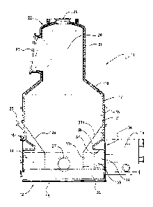
The metallurgical vessel is denoted generally as 11 and
has a hearth 12 which includes a base 13 and sides 14
formed of refractory bricks, a forehearth 15 for
discharging molten metal continuously and a tap hole 16
for discharging molten slag.
The base of the vessel is fixed to the bottom end
of an outer vessel shell 1.7 made of steel and comprises a
cylindrical main barrel section 18, an upwardly and
inwardly tapering roof section 19, and an upper
cylindrical section 21 and lid section 22 defining an
offgas chamber 26. Upper cylindrical section 21 is
provided with a large diameter outlet 23 for offgases and
the lid 22 has an opening 24 in which to mount a
downwardly extending gas injection lance (not shown) for
delivering a hot air blast into the upper region of the
vessel. The main cylindrical section 18 of the shell has
eight circumferentially spaced tubular mountings 25
through which to extend solids injection lances (not
shown) for injecting iron ore, carbonaceous material, and
fluxes into the bottom part of the vessel.
In use the vessel contains a molten bath of iron
and slag and the upper part of the vessel must contain hot
gases under pressure and extremely high temperatures of
CA 02652236 2008-11-14
WO 2007/134382 PCT/AU2007/000688
- 13 -
the order of 1200 C. The vessel is therefore required to
operate as a pressure vessel over long periods and it must
be of robust construction and completely sealed. Access
to the interior of the vessel is extremely limited, access
essentially being limited on shut down through lid opening
24 and reline access doors 27.
Vessel shell 17 is internally lined with a set of
cooling panels 31 through which cooling water can be
circulated and these cooling panels are coated with
refractory material to provide a water cooled internal
refractory lining for the vessel above the smelting zone.
It is important that the refractory lining be virtually
continuous and that all of the refractory material be
subject to cooling as uncooled refractory will be rapidly
eroded. The panels are formed and attached to the shell
in such a way that they can be installed internally within
the shell 17 and can be removed and replaced individually
on shut down without interfering with the integrity of the
shell. The construction and installation of panels 31 may
be carried out in the manner fully disclosed in US Patent
6,267,799 and International Patent Publication WO
96/31627.
The base 13 of hearth 12 of the vessel is formed
by deep refractory bricks 32 and the side 14 of the hearth
is lined with successive courses of refractory bricks 33.
The upper part 12a of the hearth tapers upwardly and
outwardly to the vessel wall 18. In use of the vessel
this part of the hearth is exposed to splashing with
molten metal and slag. In accordance with the present
embodiment this part of the hearth incorporates a cooler
denoted generally as 34 disposed outwardly behind the
bricks 33a lining the upper part of the hearth and
disposed below the lowermost part of the cooling panels 31
on the side walls of the vessel.
CA 02652236 2008-11-14
WO 2007/134382 PCT/AU2007/000688
- 14 -
Cooler 34 is formed by a series of individual
cooler panel elements 35 disposed in an array extending
circumferentially in the upper part of the hearth. It has
a stepped upper cooling surface 36 extending upwardly and
outwardly immediately behind the refractory lining 33a of
the upper part of hearth 12 and a bottom flat cooling
surface 37 resting on refractory bricks of the cylindrical
courses of bricks 33b lining the side of hearth 12 below
the upper part of the hearth.
Each cooler element 35 is self-supporting with
respect to the underlying refractory bricks of the hearth
12. Specifically, each cooler element 35 is mounted to
the outer vessel shell 17, as described hereinafter. It
is noted that, whilst the cooler elements 35 are not
supported significantly by the refractory bricks, the
cooler elements nevertheless have the effect of assisting
retaining the refractory bricks in place and reducing the
tendency of the bricks to floating within the molten bath.
As most clearly seen in Figures 4 to 6, each
cooling element 35 of cooler 34 comprises a hollow open
backed cast shell structure 41 having a base wall 42 a top
wall 43, a pair of side walls 44, and a front wall 45.
The base wall 42 and the side walls 44 are flat with
continuous outwardly facing surfaces whereas the top wall
43 inclines downwardly to the front wall 45 of the shell
structure 41. Top wall 43 may be stepped such that its
upper outwardly facing surface, which is a continuous
surface, has a series of stepped tier surfaces 46
extending across the element to support refractory bricks
47 of the refractory lining 33a of the upper part of the
hearth 12.
The shell 41 of each cooler element 45 is cast as
a unitary structure in a metal of high thermal
conductivity such as copper or a copper alloy. A pair of
CA 02652236 2008-11-14
WO 2007/134382 PCT/AU2007/000688
- 15 -
copper or nickel (or alloy) tubes 48a, 48b are cast within
this structure so as to form a series of coolant flow
passages disposed in an array extending throughout the
base, top and side walls 42, 43, 44, respectively, of the
cooler element. The casting method disclosed in US patent
6,280,681 is suitable for forming the cooler element 45.
Each tube 48a, 48b is formed initially as a
straight length of tube and then bent into a required
serpentine arrangement, discussed further below, and
positioned in a mould in which molten metal is
subsequently poured to form the cast structure. The
arrangement of tubes 48a, 48b shown in the Figures is
typical of a number of different arrangements that could
be used to achieve an appropriate flow of coolant
(generally but not necessarily water) through the walls of
the cooler element 35.
With reference to Figures 7 and 8, the tubes 48a,
48b forming the coolant flow passages extend from the
upper part of the open back of the cooler element 35 and
are fitted with inlet connectors 61 and outlet connectors
51 for flow of coolant to and from the coolant flow
passages defined by the tubes 48a, 48b.
Specifically, the inlet ends of the tubes 48a,
48b extend outwardly to the left side wall 44 as shown in
Figures 4, 7, and 8, and then forwardly a short distance
in the plane of the top wall 43 and then across the top
wall 43 to the right side wall 44 as shown in the Figures.
This basic arrangement of the tubes 48a, 48b is repeated
along the top wall 43 and down the front wall 45 until the
tubes 48a, 48b reach the base wall 42 at the front of the
cast shell structure 41. The tubes 48a, 48b then extend
in a return path to the outlet connectors 51 in the open
back of the cooling element 35. Specifically, the tubes
48a, 48b extend rearwardly a short distance in the plane
CA 02652236 2008-11-14
WO 2007/134382 PCT/AU2007/000688
- 16 -
of one of the side walls 44, across the base wall 42 to
the other side wall 44, vertically up to the top wall 43,
rearwardly a short distance in the plane of the side wall
44, vertically downwardly to the base wall 42, and across
the base wall 42 to the other side wall. The basic
arrangement is then successively repeated until the tubes
48a, 48b reach the outlet connectors 51.
A screw threaded stud 40 projects outwardly from
the upper part of the open back of each cooler element 35
between the respective inlet and outlet connectors 51.
The cooler elements are firmly fastened in position by
resting their lower back parts on steel foot plates 50
welded to the outer steel shell 17 of vessel 11, passing
the threaded studs 40 through holes in shell 17 and
completing the fastenings by fitting nuts 60 to the studs.
In this way, the cooler elements 35 are supported by the
outer steel shell 17 rather than by the underlying
refractory bricks in the hearth 12. Hence, it is possible
to replace the refractory bricks without having to also
remove the cooler elements 35.
Each cooler element 35 is shaped as a ring
segment with the side walls 41 convergent and the cooler
is formed by a plurality of those elements disposed side
by side to form a circular ring cooler 34 with the base
walls 42 of the cooler elements 35 forming a flat ring
base, the top walls 43 of the cooler elements 35 forming
an upwardly and outwardly inclined ring surface and the
side walls 44 of the cooler elements 35 extending radially
of the ring.
The inner and outer margins of each cooler
element 35 are curved to extend circumferentially of the
ring. Where steps are located in the top wall 43 they may
also be curved so that the flat tier surfaces 47 of the
cooler elements 35 together form a series of circular
CA 02652236 2008-11-14
WO 2007/134382 PCT/AU2007/000688
- 17 -
tiers extending around the circular half of the vessel.
The vertical step surfaces between the upper tier
surfaces 46 are provided with linear grooves 52 which
extend across each element 35 and in the assembled cooler
line up to form annular grooves into which a flexible
castable material can be packed to form seals between the
stepped surface of the cooler and the refractory bricks
47. Additional groove 53, 54 are formed in the flat upper
and lower outwardly facing surfaces of each cooler element
35 to extend across the cooler element 35 and to receive
castable packing material to abut courses of refractory
bricks immediately above and immediately below the cooler
34.
In the illustrated embodiment of the invention
the refractory lining of the upper part of the hearth 12
is efficiently cooled and supported by the cooler 34 and
this significantly reduces the rate of erosion of the
refractory material. Operation of the cooler 34 also
causes slag to freeze onto its surface if all of the
refractory is eroded away. The incorporation of the
cooler into the upper part of the hearth 12 prevents slag
and molten metal from washing in behind or underneath the
bottom row of cooling panels 31 as can occur in the event
that the refractory in the slag zone were to erode
completely.
The described embodiment of the invention has
been advanced by way of example only and it is to be
understood that the invention is not limited to the
constructional detail of that embodiment.
By way of example, although the cooler elements
35 with stepped upper walls forming upright wall sections
at the front margins of those elements is one option,
another option is to modify this construction such that
CA 02652236 2008-11-14
WO 2007/134382 PCT/AU2007/000688
- 18 -
the top walls 43 meet the base walls at an acute angle or
join with upright front walls at the front parts of those
elements. The top wall 43 could be formed without steps
and with a generally conically curved upper (although
still retaining annular grooves into which flexible
castable material can be packed) and the overlaying
refractory bricks could thus be shaped to smoothly abut
that upper surface. This option is schematically shown in
Figure 7. It is to be understood that this and many other
variations will fall within the scope of the invention.
Further, it is understood that while the cooling
elements 35 are cast with an open-backed shell structure,
the addition of a backing plate, whether fixed or
otherwise does not limit the invention.
Further, the present invention is not confined to
the particular arrangement of tubes 48a, 48b in the
cooling element 35 shown in the Figures. In an
alternative, although not the only other possible
alternative, arrangement, the inlet end of one of the
tubes extends outwardly to the right side wall 44 as shown
in Figures 4, 7, and 8, and then vertically downwardly to
the base wall 42, across the base wall 42 to the left side
wall 44 as shown in the Figures, vertically upwardly to
the top wall 43, forwardly and then vertically downwardly
in the plane of the side wall 44 to the base wall 41, and
then across the base wall 42 to the right side wall 44 as
shown in the Figures. This basic arrangement of the tube
is repeated until the tube 48a reaches the front of the
cast shell structure 41. The basic arrangement is then
reversed and successively repeated until the other tube
reaches the outlet connection 51. In addition, the inlet
end of the tube extends outwardly to the to the left side
wall 44 as shown in Figures 4, 7, and 8, and then
forwardly a short distance in the plane of the top wall 43
and then across the top wall 43 to the right side wall 44
CA 02652236 2008-11-14
WO 2007/134382 PCT/AU2007/000688
- 19 -
as shown in the Figures. This basic arrangement of the
tube is repeated along the top wall 43 and down the front
wall 45 until the tube reaches the base wall 42 at the
front of the cast shell structure 41. The basic
arrangement is then reversed and successively repeated
until the tube reaches the outlet connector 51.