Note : Les descriptions sont présentées dans la langue officielle dans laquelle elles ont été soumises.
CA 02653323 2008-11-25
WO 2007/137423 PCT/CA2007/000955
Pivoting, Multi-Configuration Mobile Device with Auto Change
FIELD
The technology described in this patent document relates generally to the
field of
user input mobile devices. More particularly, the patent document describes
pivoting
keypads and displays for use in a mobile device.
BACKGROUND
Different standard keyboard arrangements are known. The most widely used
English-language alphabetic key arrangement is the QWERTY arrangement. Other
types
of standard English-language alphabetic key arrangements include the QWERTZ
arrangement, the AZERTY arrangement, and the DVORAK arrangement. Each of these
arrangements, when presented as a full-size keyboard, utilizes 26 keys for 26
different
characters.
Numeric characters are often presented along with alphabetic characters on
keyboards of communication devices, such as telephones. One standard setting
body, the
International Telecommunications Union ("ITU"), has established phone
standards for the
arrangement of alphanumeric keys. One such standard, corresponds to ITU
Standard
E.161, entitled "Arrangement of Digits, Letters, and Symbols on Telephones and
Other
Devices That Can Be Used for Gaining Access to a Telephone Network" (also
known as
ANSI TI.703-1995/1999 and ISO/IEC 9995-8:1994). According to this standard,
ten keys
are used to present the alphabetic characters A-Z and the numbers 0-9. In
order to enter
alphabetic characters, the user may be required to tap the keys multiple times
until the
desired character appears on a display screen, among other known entry
techniques.
Mobile communication devices that include a combined alphabet entry keyboard
and a telephony keyboard are known. Examples of such mobile communication
devices
include mobile stations, cellular telephones, wireless personal digital
assistants (PDAs),
two-way paging devices, and others. Combining a traditional-style text-entry
keyboard
(e.g., a QWERTY-style keyboard) with a traditional-style telephony keyboard on
the same
mobile communication device typically involves undesirable ergonomic and/or
non-
intuitive user interface compromises. Furthermore, a certain keypad
configuration that is
desirable for one application will not always be desirable for a second or
third application.
The size of the keyboard is often limited by the size of the device, making
the keyboard
CA 02653323 2008-11-25
WO 2007/137423 PCT/CA2007/000955
more difficult to use. It is thus desirable to have fewer but larger keys to
perform
alphanumeric and telephony functions.
SUMMARY
A mobile device includes a keypad portion, a display portion, a plurality of
input
devices, and a processor. The display portion includes a display screen and is
rotatably
coupled to the display portion so that the keypad portion and display portion
can be rotated
with respect to each other between at least a first configuration and a second
configuration.
The plurality of input devices are associated with at least one of the keypad
portion and
the display portion. The processor is coupled to one of the keypad portion or
the display
portion and is operable to run a plurality of software applications. The
plurality of
software applications include a first software application for operation of
the device in the
first configuration and a second software application for operation of the
device in the
second configuration. The processor is operable to automatically select and
run either the
first or second software application depending on the configuration of the
device.
In the first configuration, the first software application may be a telephony
application, and in the second configuration the second software application
may be a text-
entry application. At least one of the plurality of input devices may be
operable to
override the automatically run software application to allow a user to
manually select a
chosen software application from one of the plurality of software applications
to run in a
selected configuration.
In the first configuration, the plurality of input devices may include a first
set of
input devices that is exposed for operation by a user. In the second
configuration, the
plurality of input devices may include a second set of input devices that is
exposed for
operation by the user. A dual-function set of input devices may include one or
more input
devices that are situated on the keypad portion, and the dual-function set of
input devices
are part of both the first and second sets so that they are operable in both
the first and
second configurations.
The keypad and display portions may be rotatable about an axis that runs from
the
front of the device where the keys are exposed, to the back of the device that
faces
opposite the front side. The display portion and keypad portion may face the
same
direction while rotating to two or more configurations.
2
CA 02653323 2008-11-25
WO 2007/137423 PCT/CA2007/000955
When the device is in the first configuration, rotation may be blocked in one
of
either a clockwise or counterclockwise direction, and when the device is in
the second
configuration rotation may be blocked in the opposite direction. A detent may
be coupled
to at least one of the keypad and display portions to inhibit rotation into
and out of the first
and second configurations.
In the first configuration, the plurality of input devices may comprise a
first set of
keys on the keypad portion that is available for operation by a user, and the
first set of
keys may be arranged in a three-by-four standard telephone arrangement. In the
second
configuration, the plurality of input devices may include a second set of keys
that is
exposed and available for operation by the user, and the second set of keys
may include a
key arrangement for text-entry, with a subset of the second set of keys having
at least a
second function for numeric entry. The key arrangement may be one of a QWERTY,
QWERTZ, AZERTY, DVORAK alphabetic arrangement, or a function layout.
In the first configuration, the plurality of input devices may include a first
set of
keys that is exposed and available for operation. In the second configuration,
the at least
one input device may include a second set of keys that is exposed and
available for
operation. A plurality of the first set of keys may have indicia that is
different in color
from indicia on a plurality of the second set of keys.
In another example, a mobile device includes a keypad portion, a display
portion,
at least one input device, and a processor. The display portion includes a
display screen,
with the keypad portion being rotatably coupled to the display portion so that
the keypad
portion and display portion can be rotated with respect to each other between
at least a
first configuration and a second configuration;. The input device is
associated with at least
one of the keypad portion and the display portion. The processor is coupled to
at least one
of the keypad portion and the display portion and is operable to a run a
plurality of
software applications. In the first configuration, the at least one input
device includes a
first set of input devices that is exposed so that the first set of input
devices can be
operated by a user. In the second configuration, the at least one input device
comprises a
second set of input devices that is exposed so that the second set of input
devices can be
operated by the user. The at least one input device further includes a dual-
function set of
input devices that are part of both the first and second sets of input devices
so that they are
operable in both the first and second configurations.
3
CA 02653323 2008-11-25
WO 2007/137423 PCT/CA2007/000955
The dual function set of input devices may be associated with a telephony
function
in the first configuration and a text-entry function in the second
configuration. The first
set of input devices may be keys that include indicia that is substantially
upright in relation
to the display in the first configuration. The second set of input devices may
be keys that
include indicia that is substantially upright in relation to the display in
the second
configuration. The dual function set of input devices may have indicia that is
substantially
upright in relation to the display in the first configuration and indicia that
is substantially
upright in relation to the display in the second configuration. The processor
may be
operable to allow the user to customize at least some of the plurality of
input devices by
remapping the functions that are associated with selected input devices.
In another example, a mobile device includes a keypad portion including a
plurality of input devices, a display portion including a display screen, and
a processor
coupled to at least one of the keypad portion and the display portion operable
to a run a
plurality of software applications. The keypad portion is coupled to the
display portion via
a coupling so that the keypad portion and display portion can be moved between
at least a
first configuration and a second configuration. The processor is coupled to at
least one of
the keypad portion and the display portion operable to a run a plurality of
software
applications. In the first configuration a first set of input devices is
selected from the
plurality of input devices and the first set of input devices is exposed for
operation by a
user. In the second configuration a second set of input devices is selected
from the
plurality of input devices and the second set of input devices is exposed for
operation by
the user. In the first configuration one or more of the second set of input
devices are
hidden underneath the display portion, and in the second configuration one or
more of the
first set of input devices is hidden underneath the display portion. The
coupling is
rotatable and located away from the center of the keypad portion in at least
one direction.
The rotatable coupling may include a single pivot point on the front side of
the
device. In the first configuration the display screen on the display portion
may be oriented
vertically with respect to the keypad portion, and in the second configuration
the display
screen on the display portion may be oriented horizontally with respect to the
keypad
portion.
In another example, a method for operating the mobile device described above
includes the steps of rotating the display portion relative to the keypad
portion to the first
configuration, and rotating the display portion relative to the keypad portion
to the second
4
CA 02653323 2008-11-25
WO 2007/137423 PCT/CA2007/000955
configuration. The processor automatically selects and runs the first software
application
in the first configuration and the second software application in the second
configuration.
The above-described mobile device may also include selective lighting of at
least
one of the keypad portion, the display portion, and the input devices.
In another example, a mobile device includes a keypad portion, a display
portion,
at least one input device, and a processor. The display portion includes a
display screen,
with the keypad portion being movably coupled to the display portion to
provide multiple
configurations for the device. The at least one input device is associated
with at least one
of the keypad portion and the display portion. The processor is housed in one
of the
keypad portion or the display portion that is operable to a run a plurality of
software
applications. The processor is operable to automatically select and run a
selected software
application that is selected from the plurality of software applications, with
the selected
software application being tied to the configuration of the device.
The multiple configurations for the device may include at least a first
configuration
and a second configuration, and the plurality of software applications may
include at least
a first software application and a second software application. The at least
one input
device may comprise a plurality of input devices.
The display screen may be rectangular, and, in the first configuration, the
display
screen has a tall, narrow orientation with respect to the keypad portion. In
the second
configuration, the display screen may have a short, wide orientation with
respect to the
keypad portion. The processor may be operable to allow the user to customize
at least
some of the input devices by remapping the functions that are associated with
selected
input devices.
In the first configuration the visual output of the display screen may be
automatically changed to a tall, narrow orientation and size, and in the
second
configuration the visual output of the display screen may be automatically
changed to a
shorter, wider orientation and size. The keypad portion may be movably coupled
to the
display portion by a rotatable coupling that has a single pivot point on the
front side of the
device.
In the first configuration, a first set of input devices selected from the
plurality of
input devices may be exposed so that the first set of input devices can be
operated by a
user. In the second configuration, a second set of input devices selected from
the plurality
of input devices may be exposed so that the second set of input devices can be
operated by
5
CA 02653323 2008-11-25
WO 2007/137423 PCT/CA2007/000955
the user. In the first configuration, one or more of the second set of input
devices may be
hidden underneath the display portion, and in the second configuration one or
more of the
first set of input devices may be hidden underneath the display portion. When
the device
is rotated from one configuration to another configuration, the orientation of
the visual
output of the display screen may be automatically changed to be upright with
respect to
the keypad portion in each configuration.
In another example, a mobile device includes a keypad portion having a
plurality
of input devices, a display portion including a display screen, and a
processor that is
housed in either the keypad portion or the display portion. The display
portion may have
zero or greater input devices, with the keypad portion being coupled to the
display portion
so that the keypad portion and display portion can be moved with respect to
each other to
multiple configurations that include at least a first configuration and a
second
configuration. The processor may be operable to automatically run one of a
plurality of
software applications depending upon the configuration of the device. In a
first
configuration, a first set of input devices is exposed so that the first set
of input devices
can be operated by a user. In a second configuration, a second set of input
devices may be
exposed so that the second set of input devices can be operated by a user. A
multiple-
function set of input devices includes one or more input devices that are
situated on the
keypad portion, and input devices of the multiple-function set are part of
both the first and
second sets so that they are operable in each configuration.
At least one of the input devices may be operable to override the
automatically run
software application, and allow a user to manually select a chosen application
to run in
either the first or second configuration. The keypad portion may be coupled to
the display
portion via a rotatable coupling having a single pivot point on the front side
of the device.
The rotatable coupling may be located off the center of the keypad portion in
at least one
direction.
The display portion may be at least partially superimposed over the keypad
portion
in both the first and second configurations. The display portion and keypad
portion may
face the same direction while rotating to two or more configurations.
In the first configuration the first set of input devices may comprise a first
set of
keys that is available for operation by a user, and the first set of keys may
be arranged as a
three-by-four standard telephone arrangement. In the second configuration the
second set
of input devices may comprise a second set of keys that is available for
operation by the
6
CA 02653323 2008-11-25
WO 2007/137423 PCT/CA2007/000955
user, and the second set of keys may includes a keyboard with keys for text-
entry. The
keyboard may be one of a QWERTY, QWERTZ, AZERTY, or DVORAK alphabetic
layout.
The multiple configurations may further comprise a third configuration with a
third
set of input devices situated on the keypad portion that are exposed for
operation by a user.
The multiple-function set of input devices may be part of the first, second,
and third sets
so that they are operable in each of the first, second, and third
configurations, respectively.
The processor may be programmed to automatically run a game application in the
third
configuration. The third set of input devices may have at least four keys that
are used for
directional input, and one or more keys that are used for additional input.
In the first configuration one or more of the second set of input devices may
be
hidden underneath the display portion, and in the second configuration one or
more of the
first set of input devices may be hidden underneath the display portion. The
multiple
configurations may further comprise a fourth configuration having a fourth set
of input
devices that are situated on the keypad portion and exposed so that the fourth
set of input
devices can be operated by a user. The multiple-function set of input devices
may bee part
of the first, second, third, and fourth sets so that they are operable in each
of the first,
second, third, and fourth configurations, respectively.
In a further example, a mobile device includes a keypad portion, a display
portion
including a display screen, a first set of input devices, a second set of
input devices, and a
processor. The keypad portion is coupled to the display portion so that the
keypad portion
and the display portion are movable between at least a first configuration and
a second
configuration, with both the display portion and the keypad portion facing in
the same
direction while rotating between the at least first and second configurations.
The first set
of input devices is associated with the first configuration and the second set
of input
devices is associated with the second configuration. The processor is coupled
to at least
one of the keypad portion and the display portion and is operable to run a
plurality of
software applications that are stored in the processor. In the first
configuration, a first set
of input devices is exposed so that the first set of input devices can be
operated by a user.
In a second configuration, a second set of input devices is exposed so that
the second set
of input devices can be operated by a user. In the first configuration, one or
more of the
second set of input devices are hidden underneath the display portion, and in
the second
7
CA 02653323 2008-11-25
WO 2007/137423 PCT/CA2007/000955
configuration one or more of the first set of input devices are hidden
underneath the
display portion.
The keypad portion may be coupled to the display portion by a rotatable
coupling
having a single pivot point on the front side of the device. The keypad
portion may be
coupled to the display portion by a rotatable coupling that is located off the
center of the
keypad portion in at least one direction. The display portion may completely
cover the
keypad portion in the first configuration. The mobile device may also include
means for
selectively lighting at least one of the keypad portion, the display portion,
and the input
devices.
BRIEF DESCRIPTION OF THE DRAWINGS
Fig. 1 shows a frontal view of a first example mobile device in a first
configuration;
Fig. 2 shows a frontal view of the first example mobile device in a second
configuration;
Fig. 3 shows a frontal view of the first example mobile device in a third
configuration;
Fig. 4 shows a frontal view of a second example mobile device in a first
configuration;
Fig. 5 shows a frontal view of the second example mobile device in a second
configuration;
Fig. 6 shows a perspective view of the third example mobile device in a first
configuration;
Fig. 7 shows a perspective view of the third example mobile device in a second
configuration;
Fig. 8 shows a perspective view of the fourth example mobile device in a first
configuration;
Fig. 9 shows a perspective view of the fourth example mobile device in a
second
configuration;
Fig. 10 shows a frontal view of the fifth example mobile device in a first
configuration;
Fig. 11 shows a perspective view of the fifth example mobile device as it
rotates
between the first and a second configuration;
8
CA 02653323 2008-11-25
WO 2007/137423 PCT/CA2007/000955
Fig. 11A depicts an example key for use on the device depicted in Fig. 11;
Fig. 11B depicts an alternative example key for use on the device depicted in
Fig.
11;
Fig. 12 shows a frontal view of the fifth example mobile device in the second
configuration;
Fig. 13 shows a perspective view of the sixth example mobile device in a first
configuration;
Fig. 14 shows a frontal view of the sixth example mobile device in a second
configuration;
Fig. 15 shows a frontal view of the sixth example mobile device in a third
configuration; and
Fig. 16 shows a perspective view of the seventh example mobile device in a
first
configuration;
Fig. 17 shows a frontal view of the seventh example device in a second
configuration;
Fig. 18 is a circuit schematic that is typical of the example devices
described
herein;
Fig. 19 is an illustration of a known mobile device;
Figure 20 is an illustration of an example mobile device embodying selective
keyboard illumination;
Figure 21 is an illustration of an example mobile device in a numeric mode
with
differentiated illumination levels;
Figure 22 is an illustration of the example mobile device of Figure 21 in a
full
keyboard mode at an intermediate illumination level;
Figure 23 is an illustration of an example mobile device in an alphabetic mode
with partial key illumination;
Figure 24 is an illustration of the example mobile device of Figure 23 in a
non-
alphabetic mode;
Figure 25 is an illustration of an example mobile device enabled for selective
keyboard illumination;
Figure 26 is an illustration of the example mobile device of Figure 25 in a
non-
alphabetic mode;
Figure 27 is an illustration of a known mobile device with a keypad;
9
PCT/CA2007/000955
CA 02653323 2008-11-25 31 March 2008 31-03-2008
Figure 28 is an illustration of an example mobile device having selective
keyboard
illumination in a directional mode;
Figure 29 is an illustration of an example mobile device in an alphabetic mode
with partial key illumination;
Figure 30 is an illustration of the example mobile device of Figure 29 in a
numeric
mode;
Figure 31 is a block diagram of an example mobile device incorporating a
selective
keyboard illumination system; and
Figure 32 is a flow diagram of a prior art mobile device illustrating a
process for
selective keyboard illumination that may be utilized with the example mobile
devices
described herein.
DETAILED DESCRIPTION
Examples of mobile devices that are rotatably coupled and that are useable in
two
or more configurations are described and claimed below. A configuration is a
set location
for two or more movable parts of the example device in relation to each other.
The
example devices below have several ergonomic or other interface enhancing
advantages.
The examples described below can be equipped to automatically switch the
application
that is running on the device when the user manipulates the device into each
configuration.
Furthermore, each configuration may be tailored to be optimal for the
associated
application. A group of applications may also be tied to a certain
configuration, rather
than just a single application. For example, a first configuration could be
optimized for a
cellular telephone mode and FAX mode, and a second configuration could be
optimized
for web-browsing, e-mailing, and word processing. This enhances the user
interface by
making applications quickly and easily accessible and provides for better
ergonomics and
more intuitive use of the mobile device.
Some examples reuse one or more keys for different applications in different
configurations. This results in a decrease in the size of the device since
keys are multi-
functional. Some examples have a display that automatically changes display
qualities
such as orientation and size when the user manipulates the device into each
configuration.
In these examples, the display configuration, such as wide view or narrow
view, can be
better matched with the application. Some examples partially conceal and
protect the
display screen in one configuration while revealing a part of the screen that
was previously
AMENDED SHEET
CA 02653323 2008-11-25
WO 2007/137423 PCT/CA2007/000955
covered. When the screen is exposed, greater amounts of data can be viewed.
Concealing
the screen helps to protect the unused portion of the screen from being
damaged. Some
examples are configured to provide enhanced stability and durability.
Furthermore, some
examples have two keypad portions that are rotatably connected to a display
portion
providing further opportunities for matching configurations to specific
applications.
One aspect of the examples disclosed herein is that the keypad portion and
display
portion are rotatably coupled, so that the front side of the keypad portion
and the front side
of the display portion face toward the same direction while rotating. This
rotation is about
an axis that runs from the front of the device to the back of the device. This
is opposed to
some conventional mobile devices that "flip" open by rotating about an axis
that runs from
one side to another side of a device. The fact that the display portion and
keypad portion
face the same direction while rotating to two or more configurations allows
the user to
view the display while rotating and allows the display to be in multiple
orientations and
locations relative to the keypad and still be usable with the keypad in each
of these
configurations. It allows the user to turn the device on its side or upside
down and have a
screen that changes to an upright orientation.
Another aspect of the examples disclosed herein is a system of keyboard
labeling
that displays two or more characters on a single key with a first character in
a first
orientation that corresponds to a first configuration, and a second character
that is rotated
at an approximately 90 or 180 degree angle compared to the first character. In
one
example, a set of characters can be selectively lit up according to which
configuration the
device is in. Both of these aspects allow the user to readily distinguish
which function the
key will have in each configuration.
Some of the teachings of this disclosure may also be applied to devices that
"flip"
open and closed on a side-to-side axis. Furthermore, each of the example
devices may
also include a hinge that allows the device to not only rotate but also to
"flip" open and
closed on a side-to-side axis.
1. TYPE A
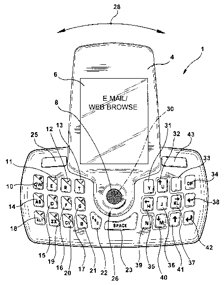
Referring now to Figure 1, an example mobile device 1 is shown in a first of
three
designated configurations. The example device 1 has two main sections: a
keypad portion
2 and a display portion 4. The display portion 4 is coupled to and partially
superimposed
over the keypad portion 2. The display portion 4 includes a display screen 6
and an input
11
CA 02653323 2008-11-25
WO 2007/137423 PCT/CA2007/000955
device 8. The input device 8, in this example, is a trackball. In other
examples, it could
also be a pointing stick, a key, a rollerball, a joystick, a wheel, or other
known input
devices. The input device could also be positioned at a different location,
such as the side
of the device. The keypad portion 2 in this first configuration has a set of
keys 10-25 that
are exposed and available for operating. The trackball 8 and the set of keys
10-25 form a
first set of input devices 8-25 that are exposed and available for operating
in the first
configuration. Other keys, thumbwheels, sliding switches, or other types of
input devices
could alternatively be included on the keypad portion 2 or display portion 4.
Notably,
there are other keys that are hidden underneath the display portion 4 in this
configuration.
The keypad portion 2 and the display portion 4 are joined together by a
rotatable
coupling 26. The coupling 26 is not visible in Figure 1, but is located
underneath the input
device 8, and at the center of the keypad portion 2. The coupling 26 allows
the display
portion 4 to be rotated with respect to the keypad portion 2. The rotational
motion is
indicated by the arrow 28, and the axis of rotation 30 runs through the device
from the
front, where the keys are exposed, to the back that faces opposite the front
of the device.
The display portion 4 and the keypad portion 2 face in the same direction
while rotating.
The display portion 4 is configured to rotate approximately 90 degrees from
the
first configuration shown in Figure 1, to the second configuration, shown in
Figure 2. The
display portion could also be rotated approximately 270 degrees from the first
configuration in the opposite direction to reach the second configuration. The
display
portion 4 can also rotate approximately 180 degrees from the first
configuration to the
third configuration shown in Figure 3. A detent or other type of mechanism for
inhibiting
but not preventing movement may be used to restrict movement once the example
device
is positioned in the first, second, or third configurations.
Alternatively, clockwise rotation from the first configuration according to
the
arrow 28 may be blocked. Counterclockwise rotation from the third
configuration
according to the arrow 28, may also be blocked. This would limit the rotation
to
approximately 180 degrees in the either direction from the first configuration
to the third
configuration. This alternative could be useful for having a stronger stopping
point at the
first and third configurations than a detent-type mechanism would provide.
Limiting
rotation also prevents excessive twisting and wear on the coupling 26 and
internal
electronic linkage.
12
CA 02653323 2008-11-25
WO 2007/137423 PCT/CA2007/000955
Referring now to Figure 2, the example mobile device 1 is shown in the second
configuration. The keypad portion 2 has a group of keys 10-23, 25, 31-43 that
are exposed
and available for operating. This group of keys 10-23, 25, 31-43 and the
trackball 8 form
a second set of input devices 8-23, 25, 31-43. Notably, one input device 24
that was
available in the first configuration is concealed under the display portion 4
and is not
available for operating, and the keys 31-43 that were hidden under the display
portion 4 in
the first configuration are now uncovered. Other keys, thumbwheels, sliding
switches, or
other types of input devices could alternatively be included on the keypad
portion 2 or
display portion 4. Many of the input devices 8-23, 25 that were part of the
first set 8-25
are also part of the second set 8-23, 25, 31-43.
In Figure 3, the example mobile device 1 is shown in the third configuration.
The
keypad portion 2 has another group of keys 22-24, 31-43 that are exposed and
available
for operating. This group of keys 22-24, 31-43 and the trackball 8 form a
third set of input
devices 8, 22-24, 31-43. The remaining keys are hidden by the display portion.
Other
keys, thumbwheels, sliding switches, or other types of input devices could
alternatively be
included on the keypad portion 2 or display portion 4. All the input devices
in the third set
8, 22-24, 31-43 except one 24 were part of the second set 8-23, 25, 31-43. Key
24 was
covered in the second configuration. Two of the input devices 22-23 that were
part of the
first set 8-25 and second set 8-23, 25, 31-43 are also part of the third set
8, 22-24, 31-43.
The trackball 8 on the display portion 4 is available for operation in all
three
configurations. Because of the central location and the fact it is available
in all
applications, a pointing device such as the trackball 8 is an ergonomically
advantageous
input device at this location.
The first configuration of the example device 1, shown in Figure 1, is
optimized
for a cellular phone application. Twelve keys 10-21 of the first set of input
devices 8-25
are set up in a traditional three by four configuration. This is a familiar
layout that is
intuitive to users and is ergonomically favorable.
In the first example device 1 both the telephony characters, "0-9, #,*" used
primarily in the first configuration, and the text-entry characters, used
primarily in the
second configuration, are printed at an approximately 45 degree angle relative
to the long
axis of the keypad portion 2. In the second configuration, the example device
1 is
preferably held at a 90 degree clockwise rotation from the first
configuration. In this
configuration, both the text and numerical indicia are at an approximately
negative 45
13
PCT/CA2007/000955
CA 02653323 2008-11-25 31 March 2008 31-03-2008
degree angle from being upright with respect to the orientation of the display
screen 6.
This key indicia scheme allows both text and numeral indicia to be easily
visible and
associated with the correct keys in both configurations. The telephone
character indicia
on the keys 10-21 that correspond to the first configuration may be color
coded so that
they are all the same color, and different from the color of indicia that
corresponds to other
configurations.
The remaining keys 22-25 of the first set of input devices 8-25, can be set up
for
other typical cellular phone functions. Functions such as autodial, redial,
initiate call, and
end call, for example, may be assigned to the remaining keys 22-25. One or
more of the
remaining keys may also be used for selecting and navigating through menu
systems of
the cellular phone application. The input device 8 on the display portion 4
may also be
used for this purpose, on its own, or in conjunction with one of the remaining
keys 22-25.
When in the first configuration, the example mobile device 1 is programmed to
automatically run a cellular telephone application. The automatic switching
capability of
the application when the device 1 is placed in this configuration is further
explained
below.
The second configuration of the example device 1, shown in Figure 2, is
optimized
for a text-entry application or group of applications. Examples of such
applications
include e-mail, internet browsing, instant messaging, text messaging, word
processing, or
any application where alphabetic characters are to be regularly input. Many of
the keys
10-23, 31-42 of the second set of input devices 8-23, 25, 31-43 are set up in
a text-entry
keyboard configuration. The key layout in this example is a twenty-four key
predictive
text keyboard that is fully described in "Keyboard Arrangement," U.S. Patent
No.
7,083,342, which is owned by the assignee of the present application. Other
key layouts,
QWERTY, AZERTY, Dvorak, Alphabetic, and/or Function layouts are also possible.
The remaining keys 25, 43 of the second set of input devices 8-23, 25, 31-43
can
be set up for other functions that are commonly used with text-entry
applications. For
example, one or more of the remaining keys 25, 43 could be user customizable
to run
certain shortcut commands. As another example, one of the remaining keys 25,
43 may be
used to alter the function of the four keys 32, 35, 37, 40 that have a cross-
shaped, four-
directional design imprinted around them, or of other keys or groups of keys.
The altered
14
AMENDED SHEET
CA 02653323 2008-11-25
WO 2007/137423 PCT/CA2007/000955
function of the keys in the cross-shaped box would allow cursor control in
four directions.
The input device 8 on the display portion 4 may also be used for cursor
control.
The text-entry keyboard keys 10-23, 31-42 in the second set of input devices 8-
23,
25, 31-43 have text-entry character indicia that is printed on each key. The
indicia is at
about a negative 45 degree angle in the second configuration with respect to
the
orientation of the display screen 6 in the second configuration. Because the
text-entry
keyboard keys 10-23, 31-42 are reused in other configurations for different
applications,
different character indicia may also be printed on the keys in a different or
the same
orientation. In this example telephony character indicia are printed on keys
10-21. The
orientation allows the telephony character indicia to also be visible at about
a negative 45
degree angle. This has the advantage of showing in a partially upright
orientation an
alternate key function (entry of a telephony character) that may be reached,
for example,
by holding down another key, or using a shift key. To help the user
differentiate what key
function is primary in the second configuration as opposed to the first
configuration the
indicia on the text-entry keyboard keys 10-23, 31-42 may be color coded so
that the
groups of keys are all the same color, and different from the color of indicia
that
corresponds to other configurations. The remaining keys 25, 43 do not have
indicia
printed on them in this example, but in other examples, they could also have
indicia that is
oriented or colored to correspond to the function of the keys at a particular
configuration.
When the example device 1 is in the second configuration, it may automatically
run a menu application that allows a user to select a text-entry application.
In other
examples, the mobile device may automatically run a text-entry application
directly, such
as an e-mail application. The automatic switching of the application when the
device 1 is
moved to the second configuration is further explained below.
The third configuration of the example device 1, shown in Figure 3, is
optimized
for a video game application. In this configuration a third set of input
devices 8, 23, 24,
31-43 is exposed and available for operation. Keys labeled 10-21 and 25 that
were
exposed in the second configuration are now covered under the display portion
4. Five
keys 32, 35-37, 40 are surrounded by a cross-shaped four-directional design
imprinted on
the face of the keyboard around the keys. Four of these keys 32, 35, 37, 40
function as a
directional controller for the video game application. To input diagonal
directional
commands a combination of two keys could be pressed. For example, a diagonal
direction
would be input when both keys labeled 32 and 37 are depressed. The middle key
36 may
CA 02653323 2008-11-25
WO 2007/137423 PCT/CA2007/000955
be designated to have no function, because it is likely to be inadvertently
pressed when the
controller keys 32, 35, 37, 40 surrounding it are pressed.
The remaining keys 22-24, 31, 33-34, 36, 38-39, 41-43 of the third set of
input
devices are also available for inputting commands to the video game
application. In
particular, the larger keys on the outer periphery of the example device 24,
43, 23 are
ergonomically desirable for the video game application. Some users may find a
configuration with the controller keys on the left, and the extra input keys
on the right to
be more favorable. To this end, the video game application could be user
customizable to
allow the user to select which keys they desire to use as extra input keys.
In another example, instead of using four keys 32, 35, 37, 40 for the
directional
control, eight keys 31-33, 35, 37, 39-41 could be used. This would add the
benefit of
having designated keys for diagonal directions. Any type of outlining around
the keys or
highlighting of the keys could be used to more clearly depict the group of
keys, including
the use of color, font, or other indicia.
Arrow characters are visible on the controller keys 32, 35, 37, 40 to
designate the
respective directional input. The indicia "start" and "pause" are also visible
on keys
labeled 34 and 42. In this embodiment, lighting of indicia on the keys is
utilized to draw
attention to the indicia. The indicia may be lit up when the device is in the
third
configuration, and unlit in the first and second configurations. This enables
the user to
readily determine that certain keys are associated with the lit-up functions
in the third
configuration. The details of a method for selectively lighting up certain
indicia on keys is
described later in the specification. In addition, selective keys may be lit
in each
configuration. It is not required that all useable keys be lit. For example,
in text entry
mode, the space and return keys could be lit because they are frequently used.
In addition,
parts of one or more key may be lit while the remaining part of the key is not
lit. This is
useful where the keys have different functions in each configuration of the
device. In one
configuration, the top half of the key, for example, is lit, and in another
configuration, the
bottom half of the key is lit.
In other examples, color coding is used to inform the user that the arrows and
start
and pause indicia correspond with the third configuration. In the example
device 1 the
arrow characters and start and pause indicia all have the same color, and this
color is
different from the other character indicia printed on the keys 32, 35, 37, 40.
Furthermore,
in some examples, the exposed part of the keypad portion 2 while in the third
16
CA 02653323 2008-11-25
WO 2007/137423 PCT/CA2007/000955
configuration can be colored to correspond with the color of the indicia on
the keys used
in the third configuration. This color coding can also be used for the First
Configuration.
For example, the keypad portion 2 could be one color on one half, and another
color on the
other half. The respective colors would correspond to the color of the indicia
printed on
the keys that are exposed in the first and third configurations.
In another example a fourth configuration is also possible. The fourth
configuration would be reached by rotating the display portion 4 90 degrees
counterclockwise from the third configuration. Some other application could be
preset to
automatically run in this configuration, or this configuration could be user
customizable to
automatically run whatever application the user selects.
In operation, an application signal is generated when the example device 1 is
in the
first, second, or third configuration. This signal notifies the processor to
change the
software application to the one that corresponds to the configuration the
example device is
currently positioned in.
A display signal is also generated dependent upon whether the example device 1
is
positioned in the first, second, or third configuration. This signal functions
to notify the
processor to change the size and orientation of the display according to what
configuration
the example device 1 is in.
A key lighting signal may also be generated dependent upon the configuration
of
the device. This signal functions to notify the processor to light or unlight
selective keys,
such as the arrows and "start" and "pause" indicia on the keys 32, 34, 35, 37,
40, and 42
when the device is in the third configuration. Other keys may be lit in other
configurations. The lighting and unlighting may also be accomplished more
directly by a
switch that opens and closes a circuit supplying power to the key lights.
Both the display signal and the application signal may be generated, for
example,
by a tilt switch that is activated when the example device 1 is rotated to the
first, second,
or third configuration. In other examples the switch may be activated while in
the midst of
rotating between configurations. Other types of switches may also be used to
generate the
signal.
By automatically switching modes when the configuration is changed, this saves
the user the time of having to press a key, a series of keys, or navigate a
menu system to
change to the desired application. It also ensures that the example device 1
is in the mode
that the configuration has been optimized for. The example device 1 may also
include a
17
CA 02653323 2008-11-25
WO 2007/137423 PCT/CA2007/000955
user override feature, so that the user can choose to operate some or all
applications in
configurations that are not optimized for the configuration. For example, the
user may
want to use the second configuration to dial a telephone number that is
represented by
letters.
Another important feature of the example mobile device 1 is that it reuses
some
input devices in more than one configuration for different functions and
covers some input
devices in each configuration. This allows for many keys and for optimizing
the keypad
design for multiple applications while minimizing the size and weight of the
mobile
device.
II. TYPE B
Referring now to Figure 4, a second example mobile device 100 is depicted in
the
first of two configurations. The second example device 100 has a keypad
portion 102 and
a display portion 104. The display portion 104 is coupled to and partially
superimposed
over the keypad portion 102. The display portion 104 includes a display screen
106. The
keypad portion 102 in this first configuration has a first set of input
devices 108-125, 127-
129 that are exposed and available for operating. The input device in the
center 108 in this
example is a trackball. In other examples, it could be a pointing stick, a
key, a rollerball, a
joystick, a wheel, or other known input devices. The input device could be
positioned at
other locations, such as on the side of the keypad or display portion, among
other
locations. The remaining input devices in the first set 110-125, 127-129 are
all keys in
this example. Other keys, thumbwheels, sliding switches, or other types of
input devices
could alternatively be included on the keypad portion 102 or display portion
104.
Notably, several keys are concealed underneath the display portion 104 in this
first
configuration.
The keypad portion 102 and the display portion 104 are joined together by a
rotatable coupling 126 that is positioned near the center, side edge of the
keypad portion.
The coupling is not visible in Figure 4, but is located underneath the display
portion 104
and off-center. The coupling 126 allows the display portion 104 to be rotated
with respect
to the keypad portion 102. The rotational motion is indicated by the arrow
150, and the
axis of rotation 130 runs from the front of the example device, where the keys
are
exposed, to the back of the device that faces opposite the front of the
device. The keypad
portion 102 and the display portion 104 both face the same direction while
rotating.
18
CA 02653323 2008-11-25
WO 2007/137423 PCT/CA2007/000955
The coupling 126 is located off-center so that the display portion 104 can be
rotated approximately 180 degrees in the counterclockwise direction to reach
the second
configuration shown in Figure 5 and still be partially superimposed over the
keypad
portion 102, but not covering any of the text-entry keyboard keys 110-125,
127, 131-145,
or the keys 146-148 on the side of the example device 100.
A detent or other type of mechanism for inhibiting but not preventing movement
may be used to restrict movement between the first and second configurations.
Clockwise
rotation from the first configuration according to the arrow 28 is blocked,
and
counterclockwise rotation from the second configuration according to the arrow
28, is also
blocked. This limits the rotation to approximately 180 degrees between the
first
configuration and the second configuration. Limiting rotation prevents
excessive twisting
and wear on the coupling 126 and internal electronic linkage.
Referring now to Figure 5, the second example mobile device 100 is shown in
the
second configuration. The keypad portion 102 has a second set of input devices
108-125,
127-129, 131-148 that are exposed and available for operating. One input
device 128 is
almost totally concealed under the display portion 104 and is not practically
available for
operating. In this example, all the input devices in the second set 108-125,
127-129, 131-
148 are keys except for the trackball 108. Other keys, thumbwheels, sliding
switches, or
other types of input devices could alternatively be included on the keypad
portion 102 or
display portion 104. All of the keys that were part of the first set 108-125,
127-129 are
also part of the second set 108-125, 127-129, 131-148, though one key 128 is
practically
unusable in this example and key 129 is also partially covered by the display
and
practically unusable.
The display screen 106 in the second configuration is oriented approximately
90
degrees in the counterclockwise direction when compared with the display
screen 106 in
the first configuration. This provides a wider but shorter display screen 106
in the second
configuration. This is one primary difference the second example device 100
has from the
first example device 1.
The first configuration of the second example device 100, shown in Figure 4,
is
optimized for a telephony application. Twelve keys I 11-114, 116-119, 121-124
of the
first set of input devices 108-125, 127-129 are set up in a traditional three
by four
telephone keypad configuration. This is a familiar layout that is intuitive to
users and is
ergonomically favorable.
19
CA 02653323 2008-11-25
WO 2007/137423 PCT/CA2007/000955
Indicia corresponding to the numerals 0-9 and the characters * and # are
printed on
the twelve keys 111-114, 116-119, 121-124. The indicia is oriented at an
approximately
45 degree angle with respect to the orientation of the display screen 106.
Because these
keys 111-114, 116-119, 121-124 are reused in other configurations for
different
applications, different character indicia, as shown in Fig. 4, may also be
printed on the
keys.
In the second configuration, the example device 100 is preferably held by a
user in
a 90 degree clockwise rotation from the first configuration. Accordingly, in
the second
configuration, the telephony character indicia are at an approximately
negative 45 degree
angle with respect to vertical axis of the display screen 106 in this
configuration. This key
indicia scheme allows the telephony character indicia to be easily visible in
both
configurations. The telephony function is the primary function of the keys in
the first
configuration, and it is a secondary function in the second configuration. The
secondary
function may, for example, be reached by holding down a "shift" key. The
telephone
character indicia on the keys 111-114, 116-119, 121-124 that corresponds to
the first
configuration may be color coded so that they are all the same color, and
different from
the color of indicia that corresponds to the second configuration.
The remaining keys 110, 115, 120, 125, 127-129 of the first set of input
devices
108-125, 127-129 can be set up for other typical telephony functions.
Functions such as
autodial, redial, initiate call, and end call, for example, may be assigned to
the remaining
keys 110, 115, 120, 125, 127-129. One or more of the remaining keys 110, 115,
120, 125,
127-129 may also be used for selecting and navigating through menu systems of
the
cellular phone application. The input device 108 on the display portion 104
may also be
used for this purpose on its own or in conjunction with one of the remaining
keys 110,
115, 120, 125, 127-129.
When in the first configuration the example mobile device 100 automatically
runs
a cellular telephone application. The orientation of the visual output
displayed on the
display screen 106 is also automatically switched to the tall narrow
orientation shown in
the first configuration so that the visual output display appears as upright
with respect to
the keypad portion 102. The automatic switching of the application and display
when the
device 100 is in this configuration is further explained below.
The second configuration of the second example device 100, shown in Figure 5,
is
optimized for a text-entry application or group of applications. Examples of
such
PCT/CA2007/000955
CA 02653323 2008-11-25 31 March 2008 31-03-2008
applications include e-mail, internet browsing, instant messaging, text
messaging, and
word processing. A video game application may also be included in this group
of
applications.
Many of the keys 110-124, 127, 131-145 of the second set of input devices 108-
125, 127-129, 131-148 are set up in a text-entry keyboard configuration. The
key layout
in this example is a traditional QWERTY keyboard. Other key layouts are also
possible,
for example, AZERTY, QWERTZ, Dvorak, Alphabetic, andlor Function layouts, as
well
as the twenty-four key predictive text keyboard that is fully described in
"Keyboard
Arrangement," U.S. Patent No. 7,083,342, which is owned by the assignee of the
present
application.
The remaining usable keys 125, 129, 146-148 of the second set of input devices
108-125, 127-129, 131-148 can be set up for other functions that are commonly
used with
text-entry applications. For example, one or more of the remaining usable keys
125, 129,
146-148 could be user customizable to run certain shortcut commands. As
another
example, one of the remaining keys 125, 129, 146-148 may be used to alter the
function of
the text-entry keyboard keys 110-124, 127, 131-145. For example, the altered
function of
these keys could allow the telephony characters to be entered by the keys 111-
114, 116-
119, 121-124, it could also allow four direction cursor control by another set
of keys. The
input device 108 can also be used for cursor control.
Many of the second set of input devices 108-125, 127-129, 131-148 have
character
indicia that is printed on the keys so that it is substantially upright in the
second
configuration with respect to the orientation of the display screen 106 in the
second
configuration. In particular, the text-entry keyboard keys 110-124, 127, 131-
145 have a
text-entry indicia printed on them that is in an upright orientation. Because
some of these
keys 110-124, 127 are reused in the first configuration for the cellular
telephone
application, characters corresponding to the cellular telephone application
are also printed
on some of these keys 111-114, 116-119, 121-124. The orientation provides the
user with
information that the keys labeled 110-124, 127, 131-145 have the text-entry
function in the
second configuration. The indicia on the text-entry keyboard keys 110-124,
127, 131-145
may also be color coded so that they are all the same color, and different
from the color of
indicia that corresponds to the telephony application. Altematively, selective
backlighting
of keys or parts of keys may be utilized, as explained in greater detail
below. The
remaining usable keys 125, 129, 146-148 do not have indicia printed on them in
this
21
AMENDED SHEET
CA 02653323 2008-11-25
WO 2007/137423 PCT/CA2007/000955
example, but in other examples, they could also have indicia that is oriented
or colored to
correspond to the function of the key at a particular configuration.
The wider orientation of the display screen 106 in the second configuration is
more
suitable for text-entry applications than the more narrow, taller orientation
of the first
configuration. More text can be viewed on a single line, and fewer words will
be have to
be split between the first and second lines. This improves the readability of
the visual
display.
When the second example device 100 is in the second configuration, it
automatically runs a menu application that allows a user to select a text-
entry application.
In other examples, the mobile device 100 may automatically run a text-entry
application
directly, such as an e-mail application, without requiring the user to select
that option.
The orientation of the visual output displayed on the display screen 106 is
also
automatically switched from the taller, narrower orientation of the first
configuration to
the shorter, wider orientation of the second configuration so that the visual
output display
appears as upright in the second configuration with respect to the keypad
portion 102.
An application signal is generated when the second example device 100 is in
the
first or second configurations. This signal functions to notify the processor
to change the
software application to the one that corresponds to the configuration the
second example
device 100 is currently in.
A display signal is also generated when the second example device 100 is in
the
first or second configuration. This signal functions to notify the processor
to change the
size and orientation of the display according to what configuration the second
example
device 100 is in.
Both the display signal and the application signal may be generated, for
example,
by a tilt switch that is activated when the second example device 100 is
rotated to the first
or second configuration. In other examples the switch may be activated while
in the midst
of rotating between configurations. Other types of switches or techniques may
also be
used to generate the application signal.
Just as in the first example, by automatically switching applications when the
configuration is changed, the second example device 100 saves the user the
time of having
to press a key, a series of keys, or navigate a menu system to change to the
desired
application and display orientation. It also ensures that the second example
device 100 is
in the mode that the configuration has been optimized for. The second example
device
22
CA 02653323 2008-11-25
WO 2007/137423 PCT/CA2007/000955
100 may also include a user override feature, so that the user can choose to
operate some
or all applications in configurations that are not optimized for the
configuration. For
example, the user may want to use the second configuration to dial a telephone
number
that is represented by letters.
Another important feature of the second example mobile device 100 that is
shared
with many of the other example devices, is that it reuses some input devices
108-125, 127-
128 in more than one configuration for different functions. This allows
optimizing the
keypad design for multiple applications while minimizing the size and weight
of the
second example mobile device 100.
III. TYPE C
Referring now to Figure 6, a third example mobile device 200 is depicted that
is
similar to the second mobile device 100. The device has substantially the same
configuration except that the keypad is in a reduced QWERTY arrangement and
the
keypad portion 202 has an upper keypad level 203 and a lower keypad leve1205
(including a ledge portion 207) that is recessed from the upper keypad
leve1203, the
display portion 204 is superimposed over the lower leve1205. The display
screen 206 is
substantially in the same plane as the first leve1203. There are some other
differences
noted below as well.
Similar to the second example device 100, the third example device 200 has two
configurations. In the first configuration, shown in Figure 6, the display
portion 204
covers approximately one-third of the keypad portion 202, and a first set of
input devices
208-225 remain exposed and available for pressing. The display screen 206 in
the first
configuration has a tall, narrow orientation so that the device may be used in
a vertical
orientation, where the longitudinal axis of the device is vertical.
In the second configuration, shown in Figure 7, the display portion 204 is
rotated
approximately 180 degrees relative to the keypad portion 202 on an offset axis
230, so that
a second set of input devices 208-225, 231-245 are exposed and available for
pressing.
The display screen 206 has a wider, shorter orientation than in the first
configuration.
Also different from the second example device 100, the display portion 204 of
the third
example device 200 is superimposed over the ledge 207 on a side of the device
200.
While extra input devices are not located on the ledge portion 207 in this
example, in other
23
CA 02653323 2008-11-25
WO 2007/137423 PCT/CA2007/000955
examples input devices could be located on the ledge, and they would be
covered in the
second configuration but exposed in the first configuration.
Just as in the second example device 100, the third example device 200
automatically runs a telephony application in the first configuration, shown
in Fig. 6, and a
menu to select a text-entry application in the second configuration shown in
Fig. 7. It
could also run a text-entry application directly without requiring a name
callup. The third
example device 200 also automatically switches the orientation of the visual
display
output to a tall, narrow orientation in the first configuration, and to a
short, wide
orientation in the second configuration.
One benefit of the third example device 200 is that the lower keypad level 205
serves as a support backing for the display portion 204. This design gives
added rigidity
and support to the display portion 204 and prevents damage and wear to the
rotational
coupling 226. The entire ledge portion 207 may be in close proximity to the
back of the
display portion 204 and the remaining part of the lower keypad level 205 may
have
protrusions that are in close proximity with the back of the display portion
204 to enhance
this feature.
The rotational coupling can be any known type of pivoting or rotating joint,
as
known by those of skill in the art. The joint has a transverse axis that
extends from the
front of the device to the rear of the device. One type of joint that may be
utilized is a ball
joint.
The third example device 200 can be made thinner than the second example
device
100, since the display portion 204 is level with the top of the upper keypad
level 203.
Some users may even prefer the two level keypad arrangement over the single
level
arrangement.
In addition, the edges formed where the lower keypad levels 205 and upper
keypad
levels 203 meet, serve to block rotation in the clockwise direction from the
first
configuration and in the counterclockwise direction from the second
configuration. A
detent or other type of mechanism for inhibiting but not preventing movement
may be
used to restrict movement into and out of the first and second configurations
in the
direction that is not blocked by the edge between the upper 203 and lower
keypad levels
205. Limiting rotation prevents excessive twisting and wear on the coupling
226 and
internal electronic linkage.
24
CA 02653323 2008-11-25
WO 2007/137423 PCT/CA2007/000955
IV. TYPE D
Referring now to Figure 8, a fourth mobile device 300 is depicted in a first
of two
configurations. The fourth example device 300 has a keypad portion 302 and a
display
portion 304. The display portion 304 includes a display screen 306 and a first
set of input
devices 308-325, 327 that are exposed and available for pressing. The display
portion 304
is superimposed over the keypad portion 302 in this first configuration, and
the input
devices on the keypad portion 302 are concealed underneath the display portion
304. The
input device on the upper side in this example, is a thumbwhee1327. In other
examples, it
could be a pointing stick, a key, a trackball, a joystick, or other known
input devices
positioned at the same or a different location. The remaining input devices in
the first set
308-325 are all keys in this example. Other keys, thumbwheels, sliding
switches, or other
types of input devices could alternatively be included on the keypad portion
302 or display
portion 304.
One difference between the fourth example device 300 and the other example
devices 1, 100, 200, 400, 500 is that the entire display portion 304 is
superimposed over
the keypad portion 302 in the first configuration, thereby minimizing the size
of the device
300.
The keypad portion 302 and the display portion 304 are joined together by a
rotatable coupling 326. The coupling is not visible in Figure 8, but is
located underneath
the display screen 306. The coupling 326 allows the display portion 304 to be
rotated with
respect to the keypad portion 302. The rotational motion is indicated by the
arrow 328,
and the axis of rotation 330 runs transversely from the front of the example
device 300,
where the keys are exposed, to the back of the device 300 that faces opposite
the front of
the device. The keypad portion 302 and the display portion 304 both face the
same
direction while rotating.
The coupling 326 is located behind the display screen 306 so that the display
portion 304 can be rotated approximately 180 degrees to reach the second
configuration
shown in Figure 9. In this example the rotation can be either clockwise or
counterclockwise 328. A detent or other type of mechanism for inhibiting but
not
preventing movement may be used to restrict movement into and out of the first
and
second configurations in either dirpction.
In other examples, clockwise rotation from the first configuration according
to the
arrow 328 may be blocked, and counterclockwise rotation from the second
configuration
CA 02653323 2008-11-25
WO 2007/137423 PCT/CA2007/000955
according to the arrow 328, is also blocked. A detent or other such mechanism
would then
only be used to inhibit movement in the opposite directions where movement is
possible.
This limits the rotation to approximately 180 degrees between the first
configuration and
the second configuration. Limiting rotation prevents excessive twisting and
wear on the
coupling 326 and internal electronic linkage.
Referring now to Figure 9, the fourth mobile device 300 is shown in the second
configuration. The keypad portion 302 has a second set of input devices 308-
325, 327,
331-345 that are exposed and available for operating. In this example, all the
input
devices in the second set 308-325, 327, 331-345 are keys except for the
thumbwheel 327.
Other keys, trackballs, sliding switches, or other types of input devices
could alternatively
be included on the keypad portion 302 or display portion 304. All of the input
devices that
were part of the first set 308-325, 327 are also part of the second set 308-
325, 327, 331-
345.
The display screen 306 in the second configuration is located approximately in
the
middle of the fourth example device 300. The display screen 306 in this
example is
approximately square. While the display screen size does not change in the
first and
second configurations, the orientation of the visual output does change. The
visual output
of the display screen 306 is oriented approximately 90 degrees in the
counterclockwise
direction when compared with the display screen 306 in the first configuration
so that the
visual output display has a horizontal orientation in relation to the keyboard
in the second
configuration.
The first configuration of the fourth example device 300, shown in Figure 8,
is
optimized for a cellular phone application. Twelve keys 311-314, 316-319, 321-
324 of the
first set of input devices 308-325, 327 are set up in a familiar three by four
configuration.
This is layout is intuitive to users and is ergonomically favorable.
The numerals 0-9 and the characters * and # are printed on these twelve keys
311-
314, 316-319, 321-324 so that they are upright with respect to the orientation
of the
display screen 306 in the first configuration. Because these twelve keys 311-
314, 316-
319, 321-324 are reused in other configurations for different applications,
different
character indicia may also be printed on the keys. The orientation provides
the user with
information that when the fourth example device 300 is in the first
configuration, these
twelve keys 311-314, 316-319, 321-324 have the telephony character entry
function. The
indicia on the twelve keys 311-314, 316-319, 321-324 may also be color coded
so that
26
PCT/CA2007/000955
CA 02653323 2008-11-25 31 March 2008 31-03-2008
they are all the same color, and different from the color of indicia that
corresponds to the
second configuration.
The remaining keys 308, 310, 315, 320, 325 of the first set of input devices
308-
325, 327 can be set up for other typical cellular phone functions. Functions
such as
autodial, redial, initiate call, and end call, for example, may be assigned to
the remaining
keys 308, 310, 315, 320, 325. One or more of the remaining keys 308, 310, 315,
320, 325
may also be used for selecting and navigating through menu systems of the
cellular phone
application. The thumbwhee1327 may also be used for this purpose on its own or
in
conjunction with one of the remaining keys 308, 310, 315, 320, 325.
When in the first configuration the fourth example device 300 may
automatically
run a cellular telephone application. The orientation of the visual output
displayed on the
display screen 306 is also automatically switched so that the visual output
display appears
as upright with respect to the telephony character entry keys 311-314, 316-
319, 321-324.
The automatic switching of the application and display when the device 300 in
this
configuration is further explained below.
The second configuration of the fourth example device 300, shown in Figure 9,
is
optimized for a text-entry application or group of applications. Examples of
such
applications include e-mail, internet browsing, instant messaging, text
messaging, and
word processing. A video game application may also be included in this group
of
applications.
Many of the keys 310-325, 331-345 of the second set of input devices 308-325,
327, 331-345 are set up in a text-entry keyboard configuration. The key layout
in this
example is a traditional QWERTY layout. Other key layouts are also possible,
for
example, traditional full-sized QWERTY, AZERTY, Dvorak, Alphabetic, and/or
Function
layouts, as well as the twenty-four key predictive text keyboard that is fully
described in
"Keyboard Arrangement," U.S. Patent No. 7,083,342, which is owned by the
assignee of
the present application.
The remaining key 308 of the second set 308-325, 327, 331-345 can be set up
for
other functions that are commonly used with text-entry applications. For
example, this
could be user customizable to run a certain shortcut command, or to alter the
function of
the text-entry keyboard keys 310-325, 331-345. For example, the altered
function of these
keys could allow the telephony characters to be entered by the keys labeled
311-314, 316-
319, 321-324.
27
AMENDED SHEET
CA 02653323 2008-11-25
WO 2007/137423 PCT/CA2007/000955
In the second configuration of the fourth example device 300, the
thumbwhee1327
can be used for cursor control. However, instead of using the thumb, it may be
more
easily operated by the index finger of the user in this configuration.
Similar to the devices described earlier, some of the text-entry keyboard keys
310-
325, 331-345 have a text-entry indicia printed on them that is in an upright
orientation
with respect to the orientation of the display screen 306 in the second
configuration.
Because some keys 311-314, 316-319, 321-324 of the text-entry keyboard keys
310-325,
331-345 are reused in the first configuration for the cellular telephone
application, indicia
corresponding to the cellular telephone application are also printed on these
keys 311-314,
316-319, 321-324. The upright orientation provides the user with information
that keys
310-324, 331-345 have the text-entry function in the second configuration. The
indicia on
the text-entry keyboard keys 310-324, 331-345 may also be color coded so that
they are all
the same color, and different from the color of indicia that corresponds to
the first
configuration. Selective lighting of groups of keys or sets of keys may also
be used. The
remaining usable keys 308, 325 do not have indicia printed on them in this
example, but in
other examples, they could also have indicia that is oriented or colored to
correspond to
the function of the key at a particular configuration. This gives further
information to the
user to help them discern what key function the key performs in the given
configuration.
When the fourth example device 300 is in the second configuration it
automatically
runs a menu application that allows a user to select a text-entry application.
In other
examples, the mobile device may automatically run a text-entry application
directly, such
as an e-mail application. The orientation of the visual output on the display
screen is also
automatically rotated 90 degrees from the orientation of the first
configuration so that the
visual output display appears as upright in the second configuration with
respect to the text
entry keys 310-325, 331-345.
Similar to the other example devices, an application signal is generated when
the
fourth example device 300 is in the first or second configuration. This signal
functions to
notify the processor to change the software application to the one that
corresponds to the
configuration the example device 300 is currently in.
A display signal is also generated when the fourth example device 300 is in
the
first or second configuration. This signal functions to notify the processor
to change the
orientation of the visual output of the display according to what
configuration the example
device 300 is in.
28
CA 02653323 2008-11-25
WO 2007/137423 PCT/CA2007/000955
Both the display signal and the application signal may be generated, for
example,
by a tilt switch that is activated when the fourth example device 300 is
rotated to the first
or second configuration. In other examples, the switch may be activated while
in the
midst of rotating between configurations. Other types of switches or
techniques may also
be used to generate the signal.
Just as in the other examples, by automatically switching applications when
the
configuration is changed, the fourth example device 300 saves the user the
time of having
to press a key, a series of keys, or navigate a menu system to change to the
desired
application and display orientation. It also ensures that the example device
300 is in the
mode that the configuration has been optimized for. The example device 300 may
also
include a user override feature, so that the user can choose to operate some
or all
applications in configurations that are not optimized for the configuration.
Another important feature of the fourth example mobile device 300 that is
shared
with the other example devices, is that it reuses some input devices 308-325,
327 in more
than one configuration for different functions. This allows optimizing the
keypad design
for multiple applications while minimizing the size and weight of the fourth
mobile device
300.
V. TYPE E
Referring now to Figure 10, a fifth mobile device 400 is depicted that has two
configurations. The fifth device 400 is shown in a first configuration in
Figure 10. The
fifth example device 400 differs in part from the other example devices in
that there is
only one set of input devices 410-424. In this example, the keys are toggle
keys and are
multi-functional based upon how the user presses the key. The toggle keys 410-
424 are
operable to input three, five, or (if used in conjunction with other keys,
e.g. shift or alt)
multiple signals to the processor according to which of the different surfaces
of the key
that the user presses. There are also only fifteen alphanumeric toggle keys
410-424, which
is greatly reduced from the twenty-six keys that are conventionally used to
enter text. This
allows the keyboard to be reduced in size from conventional keyboards. The
toggle keys
410-424 also may have multiple surfaces for providing tactile feedback to the
user. An
example of this is best seen in Figure 11.
The keyboard provides a user interface that includes alphabetic characters
comprising a standard alphabetic format, such as QWERTY, QWERTZ, AZERTY, or
29
CA 02653323 2008-11-25
WO 2007/137423 PCT/CA2007/000955
DVORAK, among other known formats, for text entry. Current standard alphabetic
keyboard formats utilize twenty-six keys for alphabetic characters, with each
key
representing a single alphabetic character. A preferred embodiment of the
example device
400 presents alphabetic characters in a reduced key format, with fewer columns
and keys
than the standard format. Each of the twenty-six alphabetic characters are
provided, but in
a reduced format such that each key on the keyboard represents multiple
alphabetic
characters.
The preferred reduced physical keyboard is accomplished by utilizing fewer
columns than a standard format keyboard. Because of this, the keyboard is well
suited for
application on a housing form factor similar to that of a housing associated
with a
numeric-keypad-based mobile communication device. In particular, the reduced
column
keyboard provides for reduced size devices without sacrificing speed and
convenience to a
user. The reduced key keyboard also allows for smaller devices that are more
stylish and
fashionable.
This keyboard is designed to be used in two orientations, a first orientation
where
the longest dimension of the keyboard is upright and vertical with respect to
the user, and
a second orientation, a 90 degree counter-clockwise rotation of the device 400
from the
first orientation. For purposes of describing this example keyboard the term
"column"
refers to one of the longer line of alphanumeric keys and the term "row"
refers to one of
the shorter line alphanumeric of keys.
Each toggle key 410-424 may have multiple raised surfaces as depicted in Figs.
11 A and 11 B. In the depicted example, there are four raised surfaces on each
key in the
middle column of keys 415-419, and there are two raised surfaces on each key
in the outer
columns of keys 410-414, 420-424. Each alphabetic character corresponds to one
raised
surface on one of the toggle keys 410-424. The alphabetic characters are
represented on
the keyboard by indicia, which may be positioned directly on the toggle keys
410-424, or
positioned on the keypad portion 402 of the example device 400 next to the
respective
key.
In an alternative embodiment that is not shown, multiple alphabetic characters
could be associated with each toggle position. A predictive text program could
be utilized
to determine which character is being selected. This would provide for an even
smaller
keypad form factor.
PCT/CA2007/000955
CA 02653323 2008-11-25 31 March 2008 31-03-2008
In the depicted example, the alphabetic letters are arranged on the keys in a
QWERTY layout. Keys on the first outer column of keys 410-414 have two raised
surfaces each. The ten letters in the top row of a QWERTY keyboard, "Q, W, E,
R, T, Y,
U, I, 0, P" each correspond to one of the ten raised surfaces of the five keys
in the first
outer column 410-414 as shown in Figure 10. Keys in the middle column 415-419
have
four raised surfaces each. The sixteen letters in the middle and bottom rows
of a
traditional QWERTY keyboard, "A, S, D, F, G, H, J, K, L, Z, X, C, V, B, N, M"
each
correspond to one of the twenty raised surfaces of the five keys in the middle
column 415-
419 as shown in Figure 10. The letter "L" is the only letter on the key
labeled 419, and
letters "J, K, and M" are the only letters on the key labeled 418. Other
alphabetic key
layouts are also possible, for example, AZERTY, Dvorak, Alphabetic, and/or
Function
layouts, as well as the twenty-four key predictive text keyboard that is fully
described in
"Keyboard Arrangement," U.S. Patent No. 7,083,342, which is owned by the
assignee of
the present application. As an alternative to the 3 x 5 layout, a 2 x 5 layout
could be
utilized where the "Q,W,E,R,T,Y,U,I,O,P" are on the top part of the keys in
the top row,
the "A,S,D,F,G,H,J,K,L" are on the bottom part of the keys in the top row, and
the
"X,C,V,B,N,M" are on the top part of the keys in the bottom row.
Alternatively, the
"Q,W,E,R,T,Y,U,I,O,P" could be positioned on the lower part of the keys in the
upper
row, with the "A,S,D,F,G,H,J,K,L" and "X,C,V,B,N,M" positioned on the upper
and lower
parts, respectively, of the keys in the bottom row.
There are also symbols and functions that correspond to several of the raised
surfaces on the keys labeled 418-424 in the depicted example. On the key
labeled 422 the
"space" function corresponds to two raised surfaces. These symbols and
functions are
also represented on the keyboard by indicia, which may be positioned directly
on the
toggle keys 418-424, or positioned on the keypad portion 402 of the example
device 400.
These symbols and functions include those that are typically utilized with
keyboards.
Example symbols include "=õ, õõõ i,.I,õ ,itiõ, ,,,,,, = 1,.,,, 11Tõ, õ/it,
õ>õ, I,<õ, 1111, õ@1,, õNõ, 111,
õ0/Oõ, õ/V,, õCX. p_õ, õ õ-õ , õ+õ õ_", " [ õ, õ] õ, i õ f ", J ~~ 1 õ, " Iõ,
and õ\õ, among other known
symbols. Example functions include "tab", "caps lock", "shift", "control",
"alt",
"return/enter", "backspace", "insert", "delete", "home", "end", "page up",
"page down",
"end", "escape", "pause", "break", "send", "end", "txt", "sym", and "scroll
lock", among
other known functions associated with text entry or telephony entry.
31
AMENDED SHEET
CA 02653323 2008-11-25
WO 2007/137423 PCT/CA2007/000955
The toggle keys 410-424 of the example keyboard also include a center
depressed
surface that is lower than the raised surfaces. In this example device 400,
telephony
characters, which include the numbers 0-9 and the symbols # and *, each
correspond to a
center depressed surface on one of the keys 411-414, 416-419, 421-424. The
keys
depicted are either 3-switch or 5-switch keys. The telephony characters are
arranged in a
traditional three-by-four phone arrangement where the numbers " 1, 2, 3"
correspond to
keys labeled 421, 416, 411, numbers "4, 5, 6" correspond to keys labeled 422,
417, 412,
numbers "7, 8, 9" correspond to keys labeled 423, 418, 413, and the number "0"
and
symbols "*" and "#" correspond to keys labeled 414, 419, 424. Each number is
positioned
on its own key, as with a standard phone key pad. The standard numeric phone
key
arrangement corresponds to the International Telecommunication Union ("ITU")
Standard
E.161, entitled "Arrangement of Digits, Letters, and Symbols on Telephones and
Other
Devices That Can Be Used for Gaining Access to a Telephone Network" (also
known as
ANSI TI.703-1995/1999 and ISO/IEC 9995-8:1994). The center depressed surface
gives
the user tactile information to help the user locate and differentiate the
telephony key
surfaces from the alphabetic and functional raised key surfaces.
The center depressed surfaces on keys labeled 410, 415, and 420 are reserved
for
auxiliary functions. The function which these key surfaces performs when
pressed may
depend on whether the device is in a first or second configuration as
discussed below. The
center depressed surface of these keys 410, 415, 420 is of a different shape
(diamond-
shaped with rounded edges) than the center depression of the other keys 411-
414, 416-
419, 421-424 (circular). This gives the user tactile feedback to locate and
differentiate
between these keys 410, 415, 420 and the other toggle keys 411-414, 416-419,
421-424.
Particularly, this feature helps inform the user what keys are part of the
phone pad just by
feeling the keys.
In one example, the numeric phone key arrangement may also utilize a surface
treatment on the surface of the center "5" key 417 in the form of a raised
bump. This
bump is typically standard on telephones and is used to identify the "5" key
through touch
alone. Once the user has identified the "5" key, it is possible to identify
the remainder of
the phone keys through touch alone because of their standard placement. The
bump
preferably has a shape and size that is readily evident to a user through
touch. An example
bump may be round, rectangular, or have another shape, if desired.
Alternatively, raised
32
CA 02653323 2008-11-25
WO 2007/137423 PCT/CA2007/000955
bumps may be positioned on the housing around the "5" key and do not
necessarily have
to be positioned directly on the key, as known by those of skill in the art.
Preferably, the keypad chassis uses single click domes with corner actuators
under
each toggle key 410-424. The corner actuators are positioned underneath each
raised
surface. This allows the user to press a specific raised surface of the key to
select or type a
corresponding function or character. If the center depressed surface of the
key is pressed,
the secondary key function is activated. For keys labeled 421-424, 416-419,
and 411-414
this enters a telephony character. For keys labeled 410, 415, and 420,
pressing the center
depressed surface activates some other character or operation that may be
different
depending on whether the device is in a first or a second configuration. The
single dome
design eliminates double clicking that is common in keypads with two or more
domes per
key.
The fifth example mobile device 400 has a keypad portion 402 and a display
portion 404. The display portion 404 includes a display screen 406, and the
keypad
portion includes a set of toggle keys 410-424.
In other examples, other input devices could also be part of the example
device
400. For example, a thumbwheel, a pointing stick, a key, a trackball, a
joystick, or other
known input devices could also be included.
Other than the unique key layout, three other differences exist between the
fifth
example device 400 and the other example devices and are best depicted in
Figure 11: (1)
the display portion 404 has an arm portion 403, (2) the display portion 405 is
partially
seated within the keypad portion 402, and (3) the display portion rotates in a
jackknife
manner.
The keypad portion 402 and the display portion 404 are joined together by a
rotatable coupling 426. The coupling is not visible in the figures but is
located underneath
the keypad portion 402 and at the end of the arm portion 403 of the display
portion 404.
The coupling 426 allows the display portion 404 to be rotated with respect to
the keypad
portion 402. The rotational motion is indicated by the arrow 428, and the axis
of rotation
430 runs from the front of the example device 400, where the keys are exposed,
to the
back of the device that faces opposite the front of the device 400. The keypad
portion 402
and the display portion 404 both face in the same direction while rotating.
In the first configuration, the display portion 404 is partially received into
a first
groove 405 that runs through a first and second side of the keypad portion
402. The first
33
CA 02653323 2008-11-25
WO 2007/137423 PCT/CA2007/000955
groove 405 has two sides and a floor. As the first groove 405 approaches the
outer edge of
the first side it turns at approximately a 90 degree angle and runs through
the second side
of the keypad portion 402 as it follows the outer edge of the keypad portion
402. The first
groove ends where the arm portion 403 is rotatably coupled to the keypad
portion 402 on
the second side. When the example device 400 is in the first configuration, a
first side of
the display portion 404 is received into the first side of the first groove
405, and the entire
arm portion 403 of the display portion 404 is received into the second side of
the first
groove 405. The display screen 406 is entirely visible to the user and is not
received into
the first groove 405. However in other examples, it could be partially
received into the
first groove 405 so as to partially protect the display screen 406 while still
showing
enough of the screen 406 to display at least a single line for a phone number.
The rotatable coupling 426 is located at the end of the arm portion 403 of the
display portion 404 and joins it to the keypad portion 402 at an off-center
location near an
edge of the keypad portion 404. The display portion 404 can be rotated
clockwise from
the first configuration approximately 180 degrees to reach the second
configuration shown
in Figure 12. It can also be rotated counterclockwise approximately 180
degrees from the
second configuration to reach the first configuration. The floor of the
grooves 405, 407 in
the keypad portion prevents further movement past the approximately 180
degrees
between the first and second configurations. When the fifth example device 400
is in the
first or second configuration, a detent or other mechanism that restricts but
does not
prevent movement inhibits rotation in the direction where movement is
possible.
In the second configuration, as shown in Figure 12, the display portion 404 is
partially received into a second groove 407 that runs through the second side
of the keypad
portion 402 of the fifth example device 400. The arm portion 403 is totally
received in the
second groove 407. The second groove 407 has three sides and a floor, and it
is bounded
on the other side by the arm portion 403 where it is rotatably coupled to the
keypad
portion 402. When the example device 400 is in the second configuration, a
second side
of the display portion 404 that is on the other side of the arm portion 403
from the first
side is received into the second groove 407. The entire arm portion 403 is
also received
into the second groove. The display screen 406 is not received into the second
groove 407
and is fully exposed for viewing.
34
CA 02653323 2008-11-25
WO 2007/137423 PCT/CA2007/000955
Unlike the other example devices, 1, 100, 200, 300, 500, the same set of input
devices 410-424 that are exposed and available for operating in the first
configuration are
also exposed and available for operating in the second configuration.
The display screen 406 in the second configuration is located approximately in
the
middle of the second side of the keypad portion 402. The display screen 406 is
oriented
approximately 90 degrees in the clockwise direction in relation to the input
devices 410-
424 when compared with the orientation of the display screen 406 in the first
configuration. Similar to the second example device 100, this provides a wider
but shorter
display screen 406 in the second configuration. The wider orientation is
preferable for
text-reading and typing over the taller, narrower orientation of the first
configuration.
The first configuration of the fifth example device 400, shown in Figure 10,
is
optimized for a cellular phone application. The device 400 is preferably held
with the
long edges of the device 400 upright in relation to the user. In this
orientation, the
telephony characters on keys labeled 411-414, 416-419, and 421-424 will be in
a familiar
three by four configuration. This is a familiar layout that is intuitive to
users and is
ergonomically favorable.
Telephony characters are input by pressing the depressed surface of the toggle
keys
411-414, 416-419, 421-424. The remaining toggle keys 410, 415, 420 can be
automatically switched when in the first configuration to correspond to
typical cellular
phone functions, examples of which are given above. One or more of the
depressed
surfaces of the remaining toggle keys 410, 415, 420 may also be used for
selecting and
navigating through menu systems of the cellular phone application.
When in the first configuration the fifth example device 400 automatically
runs a
cellular telephone application. The orientation of the visual output displayed
on the
display screen 406 is automatically determined so that the visual output
display appears as
upright with respect to the preferred upright orientation of the long edges of
the device
400. The automatic switching of the application and display when the device
400 in this
configuration is further explained below.
The second configuration of the fifth example device 400, shown in Figure 12,
is
optimized for a text-entry application or group of applications. The device
400 is
preferably rotated by the user and held approximately 90 degrees from the
preferred
orientation of the first configuration so that the short edges of the front of
the device 400
are vertically oriented with respect to the user. The key layout in this
example, when held
CA 02653323 2008-11-25
WO 2007/137423 PCT/CA2007/000955
in this orientation, is a QWERTY keyboard as explained in detail above. In
other
examples the key layout could be various other key layouts, examples of which
are stated
above, or derived from the disclosure above.
One advantage of this device is that telephony characters may be entered in
the
second configuration by pressing the depressed surface of the toggle keys 411-
414, 416-
419, 421-424. It is not necessary to use another key to switch the function of
the key from
alphabetic to telephony in order to enter the telephony character. When the
device is
moved to the second configuration, the depressed surfaces of the remaining
toggle keys
410, 415, 420 may be automatically switched to correspond to functions that
are
commonly used with text-entry applications. For example, a depressed surface
could be
user customizable to run a certain shortcut command, or to alter the function
of the text-
entry portions of the toggle keys 410-424. The altered function of these keys
could input
capital letters instead of lower-case letters. Other examples of functions and
symbols that
might be used are also given above.
Similar to the other example devices 1, 100, 200, 300, 500, when the fifth
example
device 400 is in the second configuration it automatically runs either a text-
entry
application directly or a menu application that allows a user to select an
text-entry
application. The display orientation on the display screen 406 is also
automatically rotated
90 degrees from the orientation of the first configuration so that the display
appears as
upright in the second configuration.
Just as in the other example devices, an application signal is generated when
the
fifth example device 400 is in the first or second configuration. This signal
functions to
notify the processor to change the software application to the one that
corresponds to the
configuration the example device 400 is currently in. A manual override switch
as
discussed above may also be included.
A display signal is also generated when the fifth example device 400 is in the
first
or second configuration. This signal functions to notify the processor to
change the
orientation of the visual output of the display according to what
configuration the example
device 400 is in.
In the fifth example device 400 both the telephony character indicia, used
primarily
in the first configuration, and the text-entry character indicia, used
primarily in the second
configuration, are printed at an approximately 45 degree angle from upright
with respect
to the orientation of the display screen 406. In the second configuration, the
example
36
CA 02653323 2008-11-25
WO 2007/137423 PCT/CA2007/000955
device 400 is preferably held in a 90 degree counter-clockwise rotation from
the first
configuration, accordingly both the text and numeric character indicia are at
an
approximately negative 45 degree angle from upright with respect to the
orientation of the
display screen 406. This key indicia scheme allows both text and numeric
indicia to be
easily visible and associated with the correct keys in both configurations.
This is different
from some of the other example devices, but is particularly appropriate in
this example
device 400 because the keys 411-414, 416-419, 421-424 have separate surfaces
for both
telephony and text entry characters. This corresponds to the advantage of this
design that
allows both numerals and text to be entered with one key press in both
configurations.
The remaining toggle keys 410, 415, 420 are not depicted as having indicia for
the center
portion of the toggle key, and these keys may be reused for different
functions in each
configuration.
If some differentiation between characters that are primarily associated with
each
mode is desired, the alphabetic indicia may be color coded so that they are
all the same
color and different from the color of the telephony indicia that is printed in
the center of
the toggle keys 411-414, 416-419, 421-424. Alternatively, selective key
lighting may be
utilized, as discussed herein.
In other examples, the indicia for telephony function could be oriented to be
upright as they would appear with respect to display screen 406 in the first
configuration,
and the text entry indicia could be oriented at approximately a 90 degree
angle in relation
to the telephony characters so that they would appear upright in the second
configuration.
VI. TYPE F
Referring now to Figure 13, a sixth example mobile device 500 is depicted that
has
three parts. The example device 500 is shown in a first configuration in
Figure 13. The
sixth example device 500 has a first keypad portion 501, a second keypad
portion 502, and
a display portion 504. The display portion 504 includes a display screen 506.
The first
keypad portion 501 is superimposed over all but a top area of the display
portion 504. The
display portion 504 is superimposed over the second keypad portion 502. Thus,
the
display portion 504 is situated between the two keypad portions 501, 502. The
first
keypad portion 501 in this first configuration has a first set of input
devices 508, 531-543
that are exposed and available for operation. Notably, the second keypad
portion 502 is
37
CA 02653323 2008-11-25
WO 2007/137423 PCT/CA2007/000955
located behind the display portion 504 and the keys on it are covered and
unusable in this
configuration.
The two keypad portions 501, 502 and the display portion 504 are joined
together
by a rotatable coupling 526. This may be a single coupling mechanism 526 that
runs
through all three portions 501, 502, 504, such as a pin that runs through
openings in each
portion 501, 502, 504. This may also be two separate couplings: one that
attaches the first
keypad portion 501 to the display portion 504, and one that attaches the
second keypad
portion 502 to the display portion 504. The coupling 526 is not visible in
Figure 4, but is
located in the center near the bottom edge of the example device 500.
The rotatable coupling 526 allows the sixth example device 500 to be rotated
into
the second configuration as shown in Figure 14. To reach the second
configuration, the
display portion 504 is rotated approximately 90 degrees in the counter-
clockwise direction
with respect to the first keypad portion 501, as shown by the first arrow 527.
The second
keypad portion 502 is rotated approximately 180 degrees in the counter-
clockwise
direction with respect to the first keypad portion 501, as shown by the second
arrow 528.
The axis of rotation 530 runs through the center of the coupling 526, through
the front of
the example device 500 where the keys 531-543 on the first keypad 501 are
exposed, to
the back of the device 500 that faces opposite the front of the device 500.
The display
p'ortion 504 and the two keypad portions 501, 502 each face in the same
direction while
rotating.
In the second configuration the sixth example device 500 has three levels. The
first keypad 501 is on the first level, the display portion 504 is on the
second level, and the
second keypad portion 502 is on the third level. In other examples, the
display portion
504 could be on the first or third levels with the two keypad portions 501,
502 occupying
the other levels.
Referring now to Figure 14, the sixth example mobile device 500 is shown in
the
second configuration. The keys 510-523 on the second keypad portion 502 are
now
uncovered and exposed and available for operation by the user. On the display
portion
504 the input device 508, which in this example is a trackball, is also now
available to the
user. The keys 531-543 on the first keypad portion 501 also remain available
to the user.
A second set of input devices 508, 510-524, 531-543 is formed by all the input
devices
available to the user in the second configuration. Other keys, thumbwheels,
sliding
switches, or other types of input devices could alternatively be included on
the keypad
38
PCT/CA2007/000955
CA 02653323 2008-11-25 31 March 2008 31-03-2008
portions 501, 502 or display portion 504. All of the keys that were part of
the first set 508,
531-543 are also part of the second set 508, 510-524, 531-543.
The display screen 506 in the second configuration is oriented approximately
90
degrees in the counterclockwise direction when compared with the display
screen 506 in
the first configuration. However, because the example device 500 in the second
configuration is designed to be held relative to the user approximately 90
degrees in the
clockwise direction compared to the first configuration, then the display need
not change
the orientation of the visual output. The display screen 506 is no longer
hidden behind the
first keypad portion 501 in the second configuration, and is now available for
full viewing.
To reach the third configuration as shown in Figure 15, the second keypad
portion
502 is rotated approximately 90 degrees counterclockwise from its position in
the second
configuration, or approximately 270 degrees in the counterclockwise direction
from it
position in the first configuration. The display portion 504 is also rotated
approximately
45 degrees in the counterclockwise direction from its position in the second
configuration,
or approximately 135 degrees in the clockwise direction from its position in
the first
configuration. In this configuration each portion 501, 502, 504 is rotated
approximately
120 degrees apart from the other. In the third configuration the example
device 500 is
designed to be held by the user approximately 45 degrees in the clockwise
direction from
the second configuration.
A detent or other type of mechanism for inhibiting but not preventing movement
may be used to restrict movement into and out of the first, second, and third
configurations. Rotation of either of the two keypad portions 501, 502 past
360 degrees in
relation to the display portion 504 is blocked to prevent excessive twisting
and wear on the
coupling 526 and internal electronic linkage.
In other examples a smaller angle between the two keypad portions 501, 502 may
be appropriate for a larger device and a larger angle may be appropriate for
smaller
devices. This is because in a smaller device greater separation between the
two keypads
501, 502 may be needed to accommodate ergonomic placement of the fingers
without the
fingers overlapping.
One extra key 544 is exposed in the third configuration. This key 544 along
with
the input devices of the second set 508, 510-524, 531-543 form the third set
of input
devices 508, 510-524, 531-544.
39
AMENDED SHEET
PCT/CA2007/000955
CA 02653323 2008-11-25 31 March 2008 31-03-2008
The folded down keypad portions 501, 502 in this example device 500 provide a
different hand grip than the other example devices 1, 100, 200, 300, 400. The
sixth
example device 500 in the third configuration is preferably held with both
hands, and the
keypad portions 501, 502 are preferably gripped with the fmgers curled behind
and to the
inside of the keypad portions and the thumbs are held above the front of the
keypad
portions 501, 502. This is similar to how one would hold a bicycle handle,
except the
thumbs are extended toward the display screen 506. This configuration is
somewhat
similar to the controllers that are plugged into non-mobile video game
consoles. Thus,
this configuration is intuitive to users that are familiar with console video
game
controllers, and it is an ergonomic improvement for game playing applications
on mobile
devices.
A detent or other type of mechanism for inhibiting but not preventing movement
may be used to restrict movement into and out of the first and second
configurations.
Counterclockwise rotation of the second keypad portion 502 and display portion
504 is
also blocked to prevent rotating them 360 degrees back to the first
configuration in the
counterclockwise direction. Limiting rotation prevents excessive twisting and
wear on the
coupling 526 and internal electronic linkage.
The first configuration of the sixth example device 500, shown in Figure 13,
is
optimized for a cellular phone application. The twelve telephony keys 531-542
are
arranged in a traditional three by four configuration. This is a familiar
layout that is
intuitive to users and is ergonomically favorable.
The numerals 0-9 and the characters * and # are printed on these twelve keys
531-
542 so that they are substantially upright with respect to the orientation of
the display
screen 506 in this configuration. Because these keys 531-542 are reused in
other
configurations for different applications, different character indicia are
also printed on the
keys. The orientation provides the user with information that when the sixth
example
device 500 is in the first configuration, these twelve keys 531-542 have the
telephony
character input function. The indicia on the twelve telephony function keys
531-542 that
correspond to the cellular phone application may also be color coded so that
they are all
the same color, and different from the color of indicia that correspond to the
other
configurations. Selective lighting may also be utilized.
The remaining key 543 of the first set 531-543, can be set up for other
typical
cellular phone functions, such as initiate call and end call.
AMENDED SHEET
PCT/CA2007/000955
CA 02653323 2008-11-25 03 September 2008 03-09-2008
The top area of the display screen 506 is not covered by the first keypad
portion
501 and information such as incoming phone numbers and the phone number that
the user
has previously dialed or is currently dialing may be displayed in this area of
the display
screen 506. Since phone applications do not typically require a lot of display
space, this
example optimizes the space utilized according to the configuration.
When in the first configuration the sixth example device 500 automatically
runs a
cellular telephone application. The automatic switching of the application
when the
device 500 in this configuration is further explained below.
The second configuration of the second example device 500, shown in Figure 14,
is optimized for a text-entry application or group of applications. Examples
of such
applications include e-mail, internet browsing, instant messaging, text
messaging, and
word processing.
Many of the keys 510-521, 531-542 of the second set of keys 508, 510-524, 531-
543 are set up in a text-entry keyboard configuration. The key layout in this
example is a
twenty-four key predictive text keyboard that is fully described in "Keyboard
Arrangement," U.S. Patent No. 7,083,342, which is owned by the assignee of the
present
application. Other key layouts are also possible, for example, traditional
QWERTY,
AZERTY, Dvorak, Alphabetic, and/or Function layouts.
The remaining usable keys 522, 524, 543, 544 of the second set 508, 510-524,
531-
544 can be set up for other functions that are commonly used with text-entry
applications.
For example, one or more of the remaining usable keys 522, 524, 543, 544 could
be user
customizable to run certain shortcut commands. As another example, one of the
remaining keys 522, 524, 543, 544 may be used to alter the function of the
text-entry
keyboard keys 510-521, 531-542. For example, the altered function of these
keys could
allow the cellular phone mode characters to be entered by the keys labeled 531-
542. It
could also allow four direction cursor control by the keys 513, 516, 521, 522.
The input
device 508 can also be used for cursor control and other functions.
Many of the second set of input devices 508, 510-524, 531-544 have indicia
that is
printed so that it is substantially upright in the second configuration with
respect to the
orientation of the display screen 506 in the second configuration. In
particular, the text-
entry keyboard keys 510-521, 531-542 have a text-entry indicia printed on them
that is in
an upright orientation. Because some of these keys 531-543 are reused in the
first
41
AMENDED SHEET
CA 02653323 2008-11-25
WO 2007/137423 PCT/CA2007/000955
configuration for the cellular telephone application, indicia corresponding to
the cellular
telephone application are also printed on these keys 531-542. The orientation
provides the
user with information that keys 510-521, 531-542 have the text-entry function
in the
second configuration. The indicia on the text-entry keyboard keys 510-521, 531-
542 may
also be color coded so that they are all the same color, and different from
the color of
indicia that corresponds to first configuration. Selective lighting may also
or alternatively
be used. The remaining usable keys 522, 524, 543, 544 do not have indicia
printed on
them in this example, but in other examples, they could also have indicia that
is oriented
or colored to correspond to the function of the key at a particular
configuration.
When the sixth example device 500 is rotated to the second configuration it
may
automatically run a menu application that allows a user to select a text-entry
application.
In other examples, when the device 500 is rotated to the second configuration,
the device
500 may automatically run a text-entry application directly, such as an e-mail
application.
The display size on the display screen 506 is also automatically switched from
only
displaying on the top area of the display screen 506 to displaying on the
entire screen 506.
The third configuration of the sixth example device 1, shown in Figure 15, is
optimized for a video game application. This is similar to the video game
configuration in
the first example device 1. Five keys 513, 516, 517, 521, 522 are surrounded
by a cross-
shaped four-directional design imprinted around them. Four of these keys 513,
516, 517,
522 function as a directional controller for the video game application. To
input diagonal
directional commands a combination of two keys could be pressed. For example,
keys
labeled 513 and 522 when pressed simultaneously would input a diagonal
direction. The
middle key 517 may be designated to have no function, because it is likely to
be
inadvertently pressed when the directional controller keys 513, 516, 521, 522
surrounding
it are pressed.
The remaining input devices of the third set 508, 510-512, 514-515, 518-520,
524,
531-544 are also available for inputting commands to the video game
application.
Because the way the sixth example device 500 in the third configuration is
designed to be
held, the user's thumbs will have the most comfortable access to the keys that
are nearest
the rotational coupling 526, such as the keys labeled 524, 531, 535, 539, 543,
and 544.
The controller keys 513, 516, 521, 522 being on the left and the extra input
keys 531, 535,
539, 543 on the right is a familiar layout that is intuitive and ergonomically
favorable to
right handed users. Left-handed users may find a configuration with the
controller keys on
42
CA 02653323 2008-11-25
WO 2007/137423 PCT/CA2007/000955
the right, such as keys labeled 531, 536, 539, and 543; and extra input keys
on the left,
such as the keys labeled 522, 524, and 544, to be more favorable. To this end,
the video
game application could be user customizable to allow the user to select which
keys they
desire to use as extra input keys.
In another example, instead of using four keys 513, 516, 521, 522 for the
directional control, eight keys 512-513, 516-517, 520-524, 544 could be used.
This would
add the benefit of having designated keys for diagonal directions.
An application signal is generated when the sixth example device 500 is in the
first, second, or third configuration. This signal functions to notify the
processor to
change the software application to the one that corresponds to the
configuration the
example device 500 is currently in.
A display signal is also generated when the sixth example device 500 is in the
first,
second, or third configuration. This signal functions to notify the processor
to change or
keep the size of the display according to what configuration the example
device is in.
Both the display signal and the application signal may be generated, for
example,
by a tilt switch that is activated when the sixth example device is rotated to
the first,
second, or third configuration. In other examples, the switch may be activated
while in the
midst of rotating between configurations. Other types of switches may also be
used to
generate the signal.
Just as in the other examples, by automatically switching applications when
the
configuration is changed, the sixth example device 500 saves the user the time
of having
to press a key, a series of keys, or navigate a menu system to change to the
desired
application and display orientation. It also ensures that the sixth example
device 500 is in
the mode that the configuration has been optimized for. The sixth example
device 500
may also include a user override feature, so that the user can choose to
operate other
applications in configurations that are not optimized for the application. For
example, the
user may want to use the second configuration to dial a telephone number that
is
represented by letters, or play a game that requires text-entry in the second
configuration.
Another important feature of the sixth example mobile device 500 that is
shared
with the other example devices, is that it reuses some input devices 508, 513,
516, 521,
522, 531-543 in more than one configuration for different functions. This
allows
optimizing the keypad design for multiple applications while minimizing the
size and
weight of the sixth mobile device 500.
43
PCT/CA2007/000955
CA 02653323 2008-11-25 31 March 2008 31-03-2008
Several alternative examples of the sixth device are contemplated. In one
example,
the second keypad portion 502 could be rotated from the first configuration
180 degrees.
The microphone for the cellular phone would be located in the end of the
second display
portion 502 and would be closer to the user's mouth when the device is held to
the ear in
this configuration. This would enhance call quality.
In another example, the first keypad portion 501 can be rotated 180 degrees.
This
would fully expose the display portion 504, including the input device 508 and
the display
screen 506. This configuration may cause an advanced cell phone application,
such as a
call log or personal phone book, to automatically run. These applications
could be
accessed more easily with the input device 508 and larger display area in this
configuration.
In another example, the keypad portions 501, 502 may be joined to the display
portion 504 by a coupling mechanism 526 that allows the keypad portions to
rotate on
three axes. For example, a joint member that allows rotation on an x axis is
attached to the
display portion by a coupling rotating on a y axis, then both the first and
second keypad
portions are attached to the joint member by a coupling that rotates on a z
axis. This
would allow the device 500 to be rotated to a second and third configuration
where the
keypad portions 501, 502, and the display portion 504 are on the same level.
This may be
preferable to some users.
Yet another example combines the three-part design of device 500, and the
jackknife feature of device 400, as depicted in Figs. 16 and 17. The display
portion 604 in
this example has a hollow recess 605 that runs underneath the display portion
604 from
one lateral side to the other and is open on the two lateral sides of the
device and closed at
the top. Alternatively, it may have two recesses that each are open at the two
lateral sides
but are closed in the middle of the device and at the top. Two keypad portions
606, 608
are rotatably connected to the display portion 604 at two pivot points 610,
612,
respectively, near the middle of the bottom edge of the front side of the
device.
In a first configuration, shown in Fig. 16, the two keypad portions 606, 608
are
partially received into the recess 605 in the display portion 609. A single
row of five or
six keys 614, 616 on each keypad portion 606, 608 remains exposed on each
lateral side
618, 620, respectively, of the display portion 604 in this configuration.
These keys are
telephony keys and the device preferably operates a cellular phone application
in this
configuration.
44
AMENDED SHEET
PCT/CA2007/000955
CA 02653323 2008-11-25 03 September 2008 03-09-2008
In a second configuration, shown in Fig. 17, the two keypad portions 606, 608
are
rotated downward approximately 90 degrees, out of the recess 605. In this
second
configuration, the two keypad portions 606, 608 are aligned longitudinally
with each other
with the display portion 604 centered above them. There are twenty to thirty-
six keys
exposed in this configuration, depending on whether there are two or three
columns of five
or six keys on each keypad. Other numbers of keys are also possible. This
number of
keys allows a full QWERTY, AZERTY, DVORAK, or Alphabetic keyboard layouts or
reduced keyboard layouts such as that described in "Keyboard Arrangement,"
U.S. Patent
No. 7,083,342, which is owned by the assignee of the present application. The
bottom
rows 614, 616 of keys on each keypad portion 606, 608 are reused in both the
first and
second configurations and have a dual function of telephony and alphabetic
character
entry. The device preferably operates a text-entry application in this second
configuration.
In each of the above-described examples, a pivot joint was utilized to connect
the
various parts of each device together. The pivot joint pivots or rotates in
the x-y plane.
The joint may alternatively be referred to as a hinge similar to the hinge
mechanism in a
prior art jack knife. The joint may include detents that align the rotational
movement of
the pivots at various steps, such as 90 , 180 , 270 , etc. The power
connection between
the parts can be a ribbon cable, a cable connection, or otherwise, and may or
may not be
part of the pivot joint. A swivel joint or ball joint could alternatively be
used. A swivel or
ball joint would allow movement in a third dimension or along a "Z" axis,
allowing for
three-dimensional movement.
VII. ADDITIONAL APPLICATIONS
In other examples, one or more of the configurations of any of the example
devices
1, 100, 200, 300, 400, 500 could be optimized for other applications. For
example, a
police application could be set up for one configuration. This configuration
would be set
up to allow police to quickly communicate with their base and would allow them
to easily
input vehicle and driver information for doing background checks, etc. This
could help
improve traffic stop times and free the police up for doing other important
tasks.
Another example application is a shopping mode where in one of the
configurations the device 1 would connect to an in store WIFI or Bluetooth
network and
be optimized for shopping related functions. The device could be used to
display product
information when the user came near a product or the user could select
products from a
AMENDED SHEET
CA 02653323 2008-11-25
WO 2007/137423 PCT/CA2007/000955
menu. The input devices would be configured to enter credit card information,
preferably
on a three by four numerical keypad, and to navigate menus, preferably with a
thumbwheel, trackball, or some other pointing device.
A further example application is one that could be configured for a particular
company. The company employees could rotate to one of the configurations and
this
would automatically provide access to the company's network and intranet. The
company
configuration would preferably be set up as a text-entry keyboard.
In some examples the device may be user customizable so that the user can
remap
input devices to desired functions in one or more configurations. For example,
in one
configuration the user could choose among several applications to be
automatically
initiated when this configuration is reached. The user could then choose
whether the keys
are to be numeric, alphabetic, or shortcut keys for certain functions. For
example, a user
could customize one configuration to automatically access a stock trading
website, and the
user could configure some keys to run a macro that would automatically
retrieve a stock
quote for a certain ticker symbol. Other keys could be designated by the user
to buy and
sell.
An additional feature that may enhance any of the example devices discussed
above 1, 100, 200, 300, 400, 500 is a spring loaded mechanism that would
enable the user
to press a button, and the device would automatically rotate to a different
configuration.
VIII. TECHNICAL DETAILS
The example mobile devices 1, 100, 200, 300, 400, 500 presented in Figs. 1-17
include similar features, such as a housing, which includes the keyboard
portion or
portions and the display portion. The devices also have similar circuitry and
communications systems. Figure 18 shows the circuitry and communications
systems that
are common to the above examples.
The display screen 616 shown in the above examples is preferably a full
graphic
LCD. However, other types of output devices may alternatively be utilized. A
processing
device 618, which is shown schematically in Figure 18, is contained within the
device 600
and may be housed in either the display portion or the keyboard portion. The
processing
device 618 controls the operation of the display 616, as well as the overall
operation of the
mobile communication device 600, in response to actuation of keys on the
keyboard 614
by the user.
46
CA 02653323 2008-11-25
WO 2007/137423 PCT/CA2007/000955
The housing may take on any of the configurations detailed above as well as
other
sizes and shapes. The keyboard 614 may include a mode selection key, or other
hardware
or software for switching between text-entry applications and telephony
applications.
In addition to the processing device 618, other parts of the mobile
communication
device 600 are shown schematically in Figure 18. These include a
communications
subsystem 700; a short-range communications subsystem; the keyboard 614 and
the
display 616, along with other input/output devices 606, 608, 610 and 612; as
well as
memory devices 617, 619 and various other device subsystems 620. The mobile
communication device 600 is preferably a two-way RF communication device
having
voice and data communication capabilities. In addition, the mobile
communication device
600 preferably has the capability to communicate with other computer systems
via the
Internet.
Operating system software executed by the processing device 618 is preferably
stored in a persistent store, such as a flash memory 617, but may be stored in
other types
of memory devices, such as a read only memory (ROM) or similar storage
element. In
addition, system software, specific device applications, or parts thereof, may
be
temporarily loaded into a volatile store, such as a random access memory (RAM)
619.
Communication signals received by the mobile communication device may also be
stored
to the RAM 619.
The processing device 618, in addition to its operating system functions,
enables
execution of software applications 630A-630N on the device 610. A
predetermined set of
applications that control basic device operations, such as data and voice
communications
630A and 630B, may be installed on the device 600 during manufacture. In
addition, a
personal information manager (PIM) application may be installed during
manufacture.
The PIM is preferably capable of organizing and managing data items, such as e-
mail,
calendar events, voice mails, appointments, and task items. The PIM
application is also
preferably capable of sending and receiving data items via a wireless network
640.
Preferably, the PIM data items are seamlessly integrated, synchronized and
updated via
the wireless network 640 with the device user's corresponding data items
stored or
associated with a host computer system. An example system and method for
accomplishing these steps is disclosed in "System And Method For Pushing
Information
From A Host System To A Mobile Device Having A Shared Electronic Address,"
U.S.
47
PCT/CA2007/000955
CA 02653323 2008-11-25 31 March 2008 31-03-2008
Patent No. 6,219,694, which is owned by the assignee of the present
application.
Communication functions, including data and voice communications, are
performed through the communication subsystem 700, and possibly through the
short-
range communications subsystem. The communication subsystem 700 includes a
receiver
750, a transmitter 752, and one or more antennas 754, 756. In addition, the
communication subsystem 700 also includes a processing module, such as a
digital signal
processor (DSP) 758, and local oscillators (LOs) 760. The specific design and
implementation of the communication subsystem 700 is dependent upon the
communication network in which the mobile communication device 600 is intended
to
operate. For example, a mobile communication device 600 may include a
communication
subsystem 700 designed to operate with the MobitexTM, Data TACTM or General
Packet
Radio Service (GPRS) mobile data communication networks and also designed to
operate
with any of a variety of voice communication networks, such as AMPS, TDMA,
CDMA,
PCS, GSM, etc. Other types of data and voice networks, both separate and
integrated,
may also be utilized with the mobile communication device 600.
Network access requirements vary depending upon the type of communication
system. For example, in the Mobitex and DataTAC networks, mobile devices are
registered on the network using a unique personal identification number or PIN
associated
with each device. In GPRS networks, however, network access is associated with
a
subscriber or user of a device. A GPRS device therefore requires a subscriber
identity
module, commonly referred to as a SIM card, in order to operate on a GPRS
network.
When required network registration or activation procedures have been
completed,
the mobile communication device 600 may send and receive communication signals
over
the communication network 640. Signals received from the communication network
640
by the antenna 754 are routed to the receiver 750, which provides for signal
amplification,
frequency down conversion, filtering, channel selection, etc., and may also
provide analog
to digital conversion. Analog-to-digital conversion of the received signal
allows the DSP
758 to perform more complex communication functions, such as demodulation and
decoding. In a similar manner, signals to be transmitted to the network 640
are processed
(e.g. modulated and encoded) by the DSP 758 and are then provided to the
transmitter 752
for digital to analog conversion, frequency up conversion, filtering,
amplification and
transmission to the communication network 640 (or networks) via the antenna
756.
48
AMENDED SHEET
CA 02653323 2008-11-25
WO 2007/137423 PCT/CA2007/000955
In addition to processing communication signals, the DSP 758 provides for
control
of the receiver 750 and the transmitter 752. For example, gains applied to
communication
signals in the receiver 750 and transmitter 752 may be adaptively controlled
through
automatic gain control algorithms implemented in the DSP 758.
In a data communication mode, a received signal, such as a text message or web
page download, is processed by the communication subsystem 700 and is input to
the
processing device 618. The received signal is then further processed by the
processing
device 618 for an output to the display 616, or alternatively to some other
auxiliary I/O
device 606. A device user may also compose data items, such as e-mail
messages, using
the keyboard 614 and/or some other auxiliary I/O device 606, such as a
touchpad, a rocker
switch, a thumb-wheel, or some other type of input device. The composed data
items may
then be transmitted over the communication network 640 via the communication
subsystem 700.
In a voice communication mode, overall operation of the device is
substantially
similar to the data communication mode, except that received signals are
output to a
speaker 610, and signals for transmission are generated by a microphone 612.
Alternative
voice or audio I/O subsystems, such as a voice message recording subsystem,
may also be
implemented on the device 600. In addition, the display 616 may also be
utilized in voice
communication mode, for example to display the identity of a calling party,
the duration of
a voice call, or other voice call related information.
The short-range communications subsystem enables communication between the
mobile communication device 600 and other proximate systems or devices, which
need
not necessarily be similar devices. For example, the short-range
communications
subsystem may include an infrared device and associated circuits and
components, or a
BluetoothTM communication module to provide for communication with similarly-
enabled
systems and devices.
A method and system for illuminating a keyboard using selective backlighting,
or
illumination, to indicate the input mode of the keyboard was discussed above.
Selective
backlighting allows different input modes to be presented to the user by
illuminating
portions of the keyboard or portion of keys corresponding to selected indicia.
Active
portions can be highlighted, through selective illumination, in a number of
ways, including
illumination at different intensity levels, or with different colors. In some
embodiments,
selective illumination according to the present invention involves
illuminating a portion of
49
CA 02653323 2008-11-25
WO 2007/137423 PCT/CA2007/000955
the keyboard that is active, while leaving inactive keys unilluminated. For
example, in a
telephone dialing application only the keys corresponding to the keys of a
numeric keypad
are both active and illuminated. The active keys need not fonm a contiguous
region. For
example, in certain embodiments, such as a game play or directional input
mode, non-
contiguous keys used to move a cursor or icon are illuminated. In other
embodiments of
the present invention, selective illumination takes the form of differential
illumination
levels for different portions of the keyboard. This allows the user of the
mobile device to
view the full keyboard in low light situations, but still differentiate active
and inactive
portions. A further embodiment provides selective illumination for each input
mode
using a different illumination color. This permits a user to readily recognize
the current
input mode. In another embodiment, selective illumination is used to
illuminate particular
indicia on each key or on selected keys. This further refinement permits the
current mode
of a key having multiple key assignments to be clearly indicated to the user.
Examples of
these embodiments are described with reference to the figures below.
While known implementations of keyboards for mobile devices utilize both multi-
mode input keyboards and backlit keyboards, they rely upon an on-screen
indicator, or
context, to indicate which of the multiple input modes is active. Figure 19
illustrates such
a mobile device. Mobile device 1050 has a display 1052 and a keyboard 1054.
Keyboard
1054 has a backlight key 1058 for activating the keyboard backlighting, and a
toggle key
1056 used to switch between an alphanumeric, or standard QWERTY keyboard, and
a
non-alphabetic input mode, such as a numeric keypad. The selection of input
modes can
be controlled either by selection of the mode through use of the toggle key
1056, another
function key, or through software. Backlight key 1058 activates a backlight
mode in
which both display 1052 and keyboard 1054 are illuminated. Backlighting of
keyboard
1054 is typically implemented by activating a series of light sources, such as
LEDs or EL
sources, situated behind keyboard 1054. Alternate embodiments known in the art
employ
light pipes to distribute light from one or more light sources to illuminate
the keyboard.
Figure 20 illustrates mobile device 1100 embodying selective keyboard
illumination according to an aspect of the present invention. Mobile device
1100 has a
display 1102 and a keyboard 1104 including a toggle key 1106 and a backlight
key 1108.
When mobile device 1100 executes an application such as a telephone dialer, in
which
only the numeric keys are active, numeric portion 1110 is illuminated, while
the remainder
of the keyboard remains unlit. In low light conditions this causes numeric
portion 1110 to
CA 02653323 2008-11-25
WO 2007/137423 PCT/CA2007/000955
be visible, while in regular light conditions it preferably provides a visible
distinction
between the illuminated and unilluminated portions. When using another
application,
such as an email application, the entire keyboard 1104 is illuminated. In one
embodiment,
the user can still use toggle key 1106 to switch or cycle between the various
input modes,
thereby causing the mobile device to cycle through the backlighting
configurations
associated with each of the defined input modes. One skilled in the art will
appreciate that
selective illumination can be used to either replace or augment on screen
indication of the
active mode.
Figure 21 illustrates a keyboard using different illumination levels to
indicate the
active portion of the keyboard. As above, the mobile device comprises a
display 1202 and
a keyboard 1204 having a toggle key 1206 and a backlight key 1208. In contrast
to the
embodiment of Figure 20, mobile device 1200 provides multiple levels of
illumination to
portions of keyboard 1204. Thus in a numeric mode, the non-numeric portion
1212 can be
backlit to an intermediate illumination level, and numeric portion 1210 can be
backlit at a
higher illumination level to provide the user of mobile device 1200 with the
ability to view
all the keys in low light conditions, but still know that the numeric keypad
is active.
Figure 22 illustrates the keyboard of Figure 21 in a full keyboard mode, where
the entire
keyboard 1204 is backlit at the intermediate level. Such differential
illumination can also
be provided as an optional mode for the embodiment described with reference to
Figure
20, to provide three different illumination modes.
Another embodiment of the present invention is illustrated in Figures 23 and
24.
Figure 23 illustrates mobile device 1300 with a display 1302 and a keyboard
1304 having
a toggle key 1306 and a backlight key 1308. Keyboard 1304 is in an alphabetic
input
mode. In this mode, selective backlighting is employed to illuminate only the
alphabetic
portion of keys having multiple key assignments. Thus portion 1314
corresponding to the
alphabetic portion of a key is illuminated while the remainder of the key is
unilluminated.
Figure 24 illustrates the keyboard of Figure 23 in a non-alphabetic mode where
selective
backlighting is employed to illuminate the non-alphabetic portion of each key,
so that
illuminated key section 1314 corresponds to the non-alphabetic portion of a
key, while the
remainder of the key remains unlit.
One skilled in the art will appreciate that the selective illumination of key
portions
can equally be employed for illuminating key portions only in an active
keyboard portion
such as numeric portion 1110 of Figure 20 when only a subset of keys in
keyboard 1304
51
CA 02653323 2008-11-25
WO 2007/137423 PCT/CA2007/000955
are needed. For example, in one implementation, a telephone dialer application
would
preferably cause only the numeric values of keys in keyboard 1304 to be
illuminated.
Additionally, the illuminated portion of the keys in keyboard 1304 would
preferably
change as the user used toggle key 1306 to switch between input modes. The
user can
preferably deactivate the backlight through use of backlight key 1308. In a
refinement of
this embodiment, the alphabetic and non-alphabetic values of the keys are
illuminated by
backlights of different colors. This allows the alphabetic and non-alphabetic
input modes
to be easily distinguished from each other by assigning a different color to
each of the
input modes, for example the alphabetic values may be illuminated by a blue
light, while
the non-alphabetic values are illuminated by a red light. One skilled in the
art will readily
appreciate that any arrangement of colors can be used, employing known color
illumination methods. One such embodiment provides partial illumination of
each key,
with all related key sections illuminated by the same light source, and
coloration provided
through the use of filters in the keys. In an alternate embodiment, alphabetic
key portions
are illuminated by a colored light source, while the non-alphabetic key
portions are
illuminated by a differently colored light source. The light source in the
above examples
can be either local, or remote as described earlier.
It should be noted that the coloration difference does not have to be strictly
related
to alphabetic and non-alphabetic values, as it can be applied to different
keyboard
portions. For example, a numeric keypad can be illuminated using one color
when a
keypad mode is involved, and the full keyboard can be lit in a different color
when a full
keyboard mode is employed. Similarly, the multi-colored backlighting of
different
portions of keyboard 1104 can also allow enhanced game control in a gaming
mode, by
providing different colored keys depending on the game function they control.
Figures 25 and 26 illustrate a further embodiment of the present invention on
mobile device 1400. The mobile device 1400, like those described above,
includes a
display 1402 and a keyboard 1404 having a toggle key 1406 and a backlight key
1408.
Through any of a number of techniques, including light cancellation and the
use of
different phosphors or composites, differential illumination can be utilized
to not only
illuminate one of the selected input modes, but also to cause the other input
values
assigned to a key to fade or become substantially invisible. Thus, keyboard
1404 in the
embodiment of Figure 25 only shows the alphabetic values for its illuminated
keys. In
contrast the same keyboard 1404 in Figure 26 obscures the alphabetic values of
the
52
CA 02653323 2008-11-25
WO 2007/137423 PCT/CA2007/000955
illuminated keys and displays only the non-alphabetic values. The obscuring of
key
values allows a plurality of values to be assigned to a single key while
minimizing the
chance of user confusion as to what the active input mode is. Thus, mobile
device 1400
can have a plurality of key assignments invoked by different modes. For
example in an
unillustrated gaming mode, the keys would display only directional arrows and
game
controls, while these key assignments would be obscured in other modes. As
noted, this
embodiment can be implemented through the use of optical cancellation, or
through the
use of different phosphors that illuminate, and distinguish themselves from
the natural
color of a key, under different lighting conditions. One skilled in the art
will readily
appreciate that a number of other such approaches can be implemented to
achieve this
result. One such approach is the use of characters colored a neutral shade to
match the
color of the key. Under backlighting, the characters become visible. To
improve optical
cancellation, a light sensor can be provided in device 1400 to detect the
ambient light
conditions. Variable strength light sources, responsive to the detected light
conditions, can
then be used to adjust the light levels and improve optical cancellation
effects. One skilled
in the art will appreciate that backlight key 1406 and toggle key 1408
operates as they did
in previously described embodiments.
Figure 27 illustrates a known mobile device 1500 having the form factor of a
standard cellular phone handset. Mobile device 1500 has keypad 1504 in the
form of a
standard telephone keypad with alphabetically-ordered alphabetic key
assignments and
display 1502.
In accordance with an aspect of the present invention, Figure 28 illustrates a
handset, as in Figure 27, in a directional mode, for use in such applications
as game play
modes and for navigating web pages. Mobile device 1600 has keypad 1604 and
display
1602. In its presently illustrated state, mobile device 1600 is in a
directional mode and
provides a directional control pad through illuminated keys 1610 on keypad
1604. Such a
directional mode is achieved using selective illumination techniques as
described above.
The embodiment of Figure 28 clearly illustrates the application of selective
illumination of
keys in a designated keyboard portion for illuminating active keys as
designated, for
example, by a software application executed on a device.
Figures 29 and 30 illustrate the illumination of key portions 1714 on keypad
1704
of mobile device 1700 to distinguish between the active modes of keypad 1704
in a
manner described in relation to Figures 23 and 24. In the alphabetic mode
shown in
53
CA 02653323 2008-11-25
WO 2007/137423 PCT/CA2007/000955
Figure 29, the illuminated key portion 7114 of each key on the keypad 1704
corresponds
to an alphabetic portion of the key, whereas the non-illuminated portion 1716
corresponds
to a numeric portion of the key. In the numeric mode shown in Fig. 30, the
portions 1714
and 1716 are reversed, such that numeric portions of keys are illuminated. One
skilled in
the art will readily appreciate that either a single color illumination, or
multi-colored
illumination of each key in keyboard 1704 can be implemented using known
methods,
including those discussed with relation to mobile device 1300 as illustrated
in Figures 23
and 24. One skilled in the art will additionally appreciate that the selective
illumination
technique described with respect to Figures 25 and 26 can be applied to a
mobile device
1700 having the form factor of a cellular phone handset without difficulty,
and without
departing from the scope of the present invention.
Figure 31 is a block diagram of mobile device 1100 illustrating an
implementation
of a selective keyboard illumination system. Backlight controller 1122 is used
to control
light sources 1124 so that the active portion of keyboard 104 is illuminated.
The
determination of which portion of the keyboard 1104 is the active portion is
made by input
mode selector 1120, which then provides backlight controller 1122 with an
indication of
the active portion. The determination of the active portion is made based on
any of a
number of factors, including, for example, the software application executed
by mobile
device 1100, the user's selection of an input mode through use of toggle key
1106, and
backlight key 1108. As described above, the application executed by mobile
device 1100
can set a preferred active mode, for example an email application may default
to
alphabetic mode, that the user can override through use of toggle key 1106. In
addition, in
some embodiments, the user can change the backlighting of the non-active
portion of the
keyboard 1104, as illustrated with respect to the embodiment of Figure 21,
through use of
the backlight key 1108. The active portion may refer to either an active
portion of the
keyboard or an active key portion as previously described.
Thus, in response to a number of factors, which may include the application
executed by mobile device 1100, and user-defined input received through
keyboard 1104,
input mode selector 1120 determines an active mode and provides backlight
controller
1122 with indication of the active mode. The communication between input mode
selector 1120 and backlight controller 1122 can be facilitated by a number of
known
techniques, including the use of a direct communication line for transmitting
an encoded
54
PCT/CA2007/000955
CA 02653323 2008-11-25 31 March 2008 31-03-2008
signal indicating the selected active mode, and the use of predetermined
registers to
indicate one of a number of predetermined active modes.
Upon receipt of the active mode from input mode selector 1120, backlight
controller 1122 controls light source 1124 to selectively illuminate keyboard
1104. In a
first embodiment, corresponding to Figure 20, upon receiving indication that
the active
input mode is a numeric mode, backlight controller 1122 activates a set of
backlights
under the portion of keyboard 1104 corresponding to the numeric portion,
illustrated as
1110 in Figure 20. Upon receipt of an indication that the active input mode is
the full
keyboard mode, backlight controller 1122 activates all the backlights behind
keyboard
1104. In another embodiment, the backlight controller 1122 controls remote
light sources
that provide illumination to the keys through the use of light pipes. In
embodiments such
as the embodiments of Figure 23 and 24, backlight controller 1122 controls
light source
1124 to illuminate portions of keys in keyboard 1104 that correspond to the
active portion.
One skilled in the art will appreciate that the use of different colored light
sources or the
illumination of different portions of keys can be achieved through the use of
known
techniques.
Input mode selector 1120 and backlight controller 1122 can be implemented
either
as standalone components, or as software modules executed by the processor of
mobile
device 1200. As standalone components, input mode selector 1120 and backlight
controller 1122 can be implemented as software specifically designed as
firmware for
execution on a specified hardware platform. Alternatively, input mode selector
1120 and
backlight controller 1122 can be designed as algorithms in an operating system
executed
by the processor of mobile device 1100, or they can be stored as firmware
routines that
can be called by the operating system executing on the processor of mobile
device 100.
Those skilled in the art will appreciate that the implementation details
provided above are
merely exemplary, and any number of implementations can be employed where the
functionality of the assigned logical blocks is spread between a number of
different
elements without departing from the scope of the present invention.
Figure 32 illustrates a method that may be utilized with the mobile device of
the
present invention. In step 1000, a control system, such as the system
illustrated in Figure
31, receives a signal that indicates that the illumination state is to be
changed. In step
1002, a determination of which of the plurality of illumination states is to
be selected is
made. One skilled in the art will appreciate that different signals received
can be received
AMENDED SHEET
PCT/CA2007/000955
CA 02653323 2008-11-25 31 March 2008 31-03-2008
in step 1000. Each of these signals is interpreted in a different manner, so
that, for
example, a first signal is interpreted as indicating the next state in a cycle
of states is to be
selected, while another signal is interpreted as indicating that a specific
illumination state
is to be selected. In step 1004, the light source used to illuminate the
keyboard, such as
light source 1124 illuminating keyboard 1104, is controlled to provide the
illumination
state determined in step 1002. Thus, step 1004 allows a mobile device, such as
one of the
mobile devices embodying aspects of the present invention previously
described, to
selectively illuminate the keyboard. As described above the selective
illumination can
take the form of illuminating portions of the keyboard using different colors,
different
illumination levels or combinations of the two.
As illustrated in Figure 32, step 1000, where a signal indicative of an
illumination
state change is received, can optionally include receiving a signal indicative
of an input
mode change 1006. The receipt of this signal in 1006 is typically in response
to the
receipt of an indication that the user has toggled the input mode, as shown in
step 1008, or
in response to the execution of an application that has a default data entry
mode, as shown
in step 1010. The indication that the user has toggled the input mode is
typically received
in response to actuation of the toggle key 1106. Alternately, step 1000 can
optionally
include the receipt of a backlight activation signal 1012, which is typically
received in
response to user actuation of the backlight key 1108. One skilled in the art
will appreciate
that a number of other events can result in the receipt of a signal indication
of an
illumination state change including timed events and detection of ambient
light conditions.
The term substantially, as used herein, is a term of approximation. The term
size
as used in reference to the visual output of the display screen encompasses
the aspect ratio
of the visual output.
While various features of the claimed invention are presented above, it should
be
understood that the features may be used singly or in any combination thereof.
Therefore,
the claimed invention is not to be limited to only the specific examples
depicted herein.
The scope of the present invention is accordingly defined as set forth in the
appended
claims.
56
AMENDED SHEET