Note : Les descriptions sont présentées dans la langue officielle dans laquelle elles ont été soumises.
CA 02653446 2008-11-21
WO 2007/136352 PCT/SG2007/000143
1
An Improved Spreader Assembly
Field of the Invention
The invention relates to spreaders used for the movement of shipping
containers
for instance at a container yard for the loading and unloading of containers
from a
container ship. More specifically the invention relates to head blocks mounted
to said
spreaders which are used to connect the cables to the spreaders through
sheaves, the
head blocks being typically detachable from said spreaders. Further still the
invention
relates to those spreaders and head blocks used for the movement of multiple
containers
at one time.
Background
The economics of processing shipping containers is volume directly
proportional
to the containers through a shipping yard. To enhance the flow of containers,
certain
apparatus has been developed whereby two containers may be moved at one time
and so
at least at this stage doubling the rate of movement of the containers.
For instance, where access to move containers is limited, it is particularly
advantageous to use apparatus that will fit within a confined space, such as
limited to a
single head block and spreader, with apparatus that includes two head blocks
and
spreaders.
CA 02653446 2008-11-21
WO 2007/136352 PCT/SG2007/000143
2
To this end it would be further advantageous if two head blocks could be used
for two
spreaders engaging two containers and, further that the spreaders or head
blocks could
be separated so as to deal with the two containers as individuals rather than
collectively.
A system has been proposed to achieve this involving arms projecting from one
head block having ball shaped ends and mounted to a second head block is a
mechanical
device for engagement that comes together to grip the balls in a pincer-type
action,
creating a ball joint between the two devices. Thus by activating the arms to
move to
position and further to have the pincers to move into position also, the head
blocks can
be engaged and disengaged accordingly.
However, in order to engage the two head blocks, the tolerance for the pincers
to
engage the balls of the projecting arms is of the order of 50mm. One can
imagine two
head blocks having spreaders attached thereto in an outdoor environment where
wind
can affect the motion of the spreaders. To engage the head blocks within a
tolerance of
50mm would be an extremely difficult activity and certainly time consuming
detracting
from the benefits offered by the dual head blocks.
Other more complex systems are known such as those having projecting arms
fornied from parallelogram linkages. Whilst useful said systems are more
complex to
manufacture and require a greater number of moving parts which could lead to-
further
maintenance.
CA 02653446 2008-11-21
WO 2007/136352 PCT/SG2007/000143
3
It would therefore be advantageous to have a head block that could be engaged
and disengaged more easily than the above mentioned system.
Statement of Invention
Therefore, in a first aspect the invention provides an engagement assembly for
mounting to a first head block so as to engage a second head block, said
assembly
comprising at least one mounting bracket for mounting the assembly to the
first head
block; a plurality of extendable members each connected at a first end to the
at least one
mounting bracket, a second opposed end of each extendable member being
extendable
away from said first head block; a plurality of engagement portions in
communication
with the second ends such that extension of the second ends consequently
extends the
engagement portions, said engagement portions adapted to engage engagement
brackets
mounted to the second head block, wherein on engagement the engagement
assembly
permits selective relative movement in the horizontal plane and free relative
vertical
movement.
In a second aspect, the invention provides a method of engaging a first head
block and a second head block, comprising the steps of: extending a plurality
of
extendable arms mounted at first ends to the first head block towards the
second head
block, said extendable arms having second ends in communication with a
plurality of
engagement portions such that extension of the second ends consequently
extends the
engagement portions; said engagement portions engaging engagement brackets
mounted
CA 02653446 2008-11-21
WO 2007/136352 PCT/SG2007/000143
4
to the second head block; permitting selective relative movement of the head
blocks in
the horizontal plane and free relative vertical movement.
In a third aspect the invention provides an engagement assembly for mounting
to
a first head block so as to engage a second head block, said assembly
comprising: at
least one mounting bracket for mounting the assembly to the first head block;
a plurality
of telescopically extendable members each connected at a first end to the at
least one
mounting bracket, a second opposed end of each telescopically extendable
member
being extendable away from said first head block; a plurality of engagement
portions in
communication with the second ends such that extension of the second ends
consequently extends the engagement portions, said engagement portions adapted
to
engage engagement brackets mounted to the second head block, wherein; on
engagement, relative movement of the head blocks in the horizontal plane is
subject to
extension of the telescopically extendable members and relative vertical
movement is
independent of the telescopically extendable members.
In a fourth aspect the invention provides a method of engaging a first head
block
and a second head block, comprising the steps of: extending a plurality of
telescopically
extendable arms mounted at first ends to the first head block towards the
second head
block, said telescopically extendable arms having second ends in communication
with a
plurality of engagement portions such that extension of the second ends
consequently
extends the engagement portions; said engagement portions engaging engagement
brackets mounted to the second head block; permitting selective relative
movement of
the head blocks in the horizontal plane and free relative vertical movement.
S CA 02653446 2008-11-21
t~-___p b('T' )f 'fl7 I '~.I fi
I Ld I .;
i ~
.. ~,1 r ~ ~ r" K
~ ~ ;
~ .
~,,M r ~~ )f"1 a' , {
~ ~
. i '! I .u~ F, 'q ;!,:?i1
4a
In a fifth aspect the invention provides an engagement assembly
for mounting to a first head block so as to engage a second head block, said
assembly comprising:
at least one mounting bracket for mounting the assembly to the first head
block;
a plurality of extendable members each connected at a first end to the at
least
one mounting bracket, a second opposed end of each extendable member
being extendable away from said first head block;
said extendable members arranged to extend the respective second ends in
1 o the same horizontal plane;
a plurality of engagement portions in communication with the second ends
such that extension of the second ends consequently extends the engagement
portions, said engagement portions adapted to engage engagement brackets
mounted to the second head block, wherein
on engagement the engagement assembly permits selective relative
movement in the horizontal plane and free relative vertical movement.
In a sixth aspect the invention provides an engagement assembly
for mounting to a first head block so as to engage a second head block, said
assembly comprising:
at least one mounting bracket for mounting the assembly to the first head
block;
.... ,,. .
+.s { a
: . ., ,`... ,
~
% CA 02653446 2008-11-21
Y, . ,.' j ,~ t i ...a _
` i =~ I, f '; .'.lf
' -, t, ` ... . f = `) "1 / d ~a i{Sa+ ~ lCj f= .:,C) ~' ~. ^.~ ~~ ~ ' i
4 i ., , ,.
~ , y ;. . ~ ~ 41
4b
a plurality of extendable members each connected at a first end to the at
least
one mounting bracket, a second opposed end of each extendable member
being extendable away from said first head block;
said extendable members capable of extending at least one extendable
i 5 member whilst maintaining the position of at least one other extendable
member;
a plurality of engagement portions in communication with the second ends
such that extension of the second ends consequently extends the engagement
portions, said engagement portions adapted to engage engagement brackets
1 o mounted to the second head block, wherein
on engagement the engagement assembly permits selective relative
movement in the horizontal plane and free relative vertical movement.
!' . . i
h
CA 02653446 2008-11-21
WO 2007/136352 PCT/SG2007/000143
As a broad concept the invention provides for a mechanical device mounted to a
first head block which extends to grip a fixed portion of an adjacent second
head block,
and following engagement permits free relative vertical movement between the
head
blocks.
The invention has several distinct advantages. First of all by having only one
side acting as a device, the complexity of the alignment of the device is
lessened by
having a single device only. Further, in an embodiment the extension and
retraction of
the engagement portions may provide for a considerably greater margin for
error as
engagement may not require a high level of precision compared to the prior
art.
Further complexity is removed by realising the hoists supporting the head
blocks
control vertical movement, and so as the invention permits free relative
vertical
movement, the assembly won't interfere with this movement and control.
In a preferred embodiment, the mounting bracket may be a single base from
which each arm extends or alternatively each arm may have an individual base;
either
alternative possibly being bolted or welded to the first head block.
In a more preferred embodiment, the assembly may engage the second head
block at a convenient appendage of the second head block. Alternatively the
second
head block may have purpose built brackets for receiving the engagement
portions. In a
still further preferred embodiment, the engagement portions may be vertical
rods
CA 02653446 2008-11-21
WO 2007/136352 PCT/SG2007/000143
6
mounted to the second head block and further may have one rod per engagement
portion. Preferably, there will be two rods to engage with two engagement
portions.
Alternatively plates may be mounted either by welding or bolting to the second
head
block having vertical slots inscribed into the plates, said slots adapted to
receive the
engagement portions.
In an alternative arrangement the assembly may engage the second head block
through lugs mounted on the extending arms for engagement with corresponding
brackets mounted to the second head block. Further still the brackets may
comprise
members having vertically aligned channels such that the lugs on insertion
within said
channels are free to move vertically but are constrained from horizontal
movement by
said channels.
In a preferred embodiment, there may be two extendable members and further
said extension of the extendable members may be through a telescopic action.
Alternatively the extension may be achieved through a linkage arrangement. In
either
case the extension may be achieved through mounting an actuator, for instance
a
hydraulic, pneumatic or electric actuator, for controlling the extension and
subsequent
retraction of the extendable members. Further on retraction of the extendable
members
having disengaged the assembly from the second head block, said extendable
members
and other portions of the assembly may lie within a planned area of the first
head block.
This has the advantage of not having any part of the assembly projecting
outside the
first head block that may be snagged or interfere with other objects during
the operation
of the first head block.
CA 02653446 2008-11-21
WO 2007/136352 PCT/SG2007/000143
7
In a more preferred embodiment, the extendable members may be arranged such
that as the members extend, the respective second ends remain in the same
horizontal
plane. Further following engagement with the second head block, the second
ends may
remain in the same horizontal plane and thus any force applied by the
extendable
members to the second head block through the second ends will be restricted to
the
horizontal plane only.
In a preferred embodiment, the lateral engagement member may include an
actuation means biasing the engagement portions into opposed directions said
directions
being co-linear with the extension axis. In a more preferred embodiment, the
actuation
means may include two separate actuators, each acting on a respective
engagement
portion. Alternatively, the actuation meaTis may include a single bi-
directional actuator
capable of independent actuation on the engagement portions and further may
include
selective arrangements of the bi-directional actuator to permit co-dependent
actuation of
the engagement portions.
Thus the actuation means of the lateral engagement member may be capable of
independently moving the engagement portions or alternatively moving the
engagement
portions in a co-dependent manner for instance having the movement of a first
engagement portion follow the movement of a second engagement portion.
In a preferred embodiment, operation of the engagement assembly may be
subjected to a control system whereby a processor processes an operator's
instruction to
activate the extendable arms and/or the lateral extension member. Further the
control
CA 02653446 2008-11-21
WO 2007/136352 PCT/SG2007/000143
8
system may include an initiation sequence whereby the assembly automatically
moves
from a first orientation to a second orientation, said first orientation being
in
disengagement with the second head block and said second orientation being in
engagement with the second head block. One such alternative arrangement for
the
initiation sequence may include automatically extending the extendable arms
until at
least one engagement portion contacts the second head block. The control
system may
then extend the second extendable arm until that respective engagement portion
also
contacts the second head block and then retracting the lateral engagement
member until
both engagement portions engage the second head block.
Thus the operation of the control system may free the operator from engagement
through an automated sequence. For instance, contact of the extendable arms
with the
second head block may be through a limit switch adjacent to this second end.
Alternatively, said contact may be detected through the use of a load cell in
communication with the second end such that on detection of an increase in
applied
load, the control system acts on said contact to move to the next step within
the
sequence.
Brief Description of Drawings
It will be convenient to further describe the present invention with respect
to the
iccompanying drawings that illustrate possible arrangements of the invention.
Other
CA 02653446 2008-11-21
WO 2007/136352 PCT/SG2007/000143
9
arrangements of the invention are possible and consequently the particularity
of the
accompanying drawings is not to be understood as superseding the generality of
the
preceding description of the invention.
Figure 1 is an isometric view of a pair of head blocks and spreaders having an
engagement assembly according to a first embodiment of the present invention;
Figure 2 is a side elevation view of the head blocks of Figure 1 together with
associated spreaders and containers;
Figure 3 is a plan view of the head blocks and spreaders according to Figures
1
and 2;
Figure 4 is a plan view of a pair of head blocks coupled using the engagement
assembly according to the first embodiment of the present invention;
Figure 5 is a side elevation view of the head blocks and engagement assembly
according to Figure 4;
Figure 6 is an elevation view of two head blocks each connected to a spreader
and a container having an engagement assembly according to the first
embodiment of
the present invention;
Figure 7 is a plan view of the head blocks and engagement assembly of Figure
4;
CA 02653446 2008-11-21
WO 2007/136352 PCT/SG2007/000143
Figure 8 is a side elevation view of the head blocks and engagement assembly
of
Figure 5;
Figure 9 is a side elevation view of the head blocks and engagement assembly
of
Figure 8;
Figure 10 is a plan view of the head blocks and spreaders of Figure 3, in a
skew
position;
Figure 11 A is a schematic view of an actuator associated with the lateral
engagement member according to a further embodiment of the present invention;
Figure 11 B is a lookup table mapping the function of the actuator of Figure
11 A.
Figure 12 is an isometric view of the engagement assembly according to a
second embodiment of the present invention;
Figure 13 is an isometric view of the engagement assembly of Figure 12
mounted to a pair of head blocks;
Figures 14A to 14C are plan views of the engagement assembly of Figure 12;
Figures 15A and 15B are isometric views of the engagement assembly of Figure
12 separating two engaged head blocks;
CA 02653446 2008-11-21
WO 2007/136352 PCT/SG2007/000143
11
Figures 16A and 16B are elevation views of a chain and sprocket arrangement
according to the second embodiment of the present invention;
Figures 17A and 17B are plan views of the engagement assembly of Figure 12
offsetting to two adjacent head blocks;
Figure 18 is a plan view of the engagement assembly of Figure 12 skewing two
adjacent head blocks and;
Figures 19A to 19D are elevation views of the engagement assembly of Figure
12 showing relative vertical movement of adjacent head blocks.
Description of Preferred Embodiment
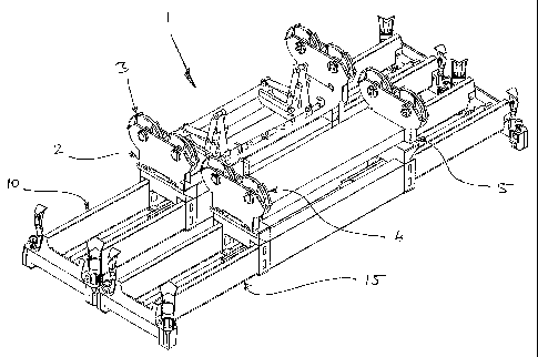
Figure 1 shows a pair of head blocks 2, 5 mounted to two spreaders 10, 15 and
placed in proximity in order to act together. Not shown are cables which would
engage
the head blocks 2, 5 through sheaves 3, 4. Further is shown an engagement
assembly 1
mounted to the first head block 2 which is adapted to engage portions on the
second
head block 5 so that together the head blocks 2, 5 can act with the spreaders
10, 15 to
move two containers simultaneously. The nature of the engagement assembly 1 is
such
that the first head block 2 can engage or disengage from the second head block
5 at any
point either at rest or in mid air and avoid the problems of the prior art
through being
relatively resistant to tolerance when engaging the second head block 5.
CA 02653446 2008-11-21
WO 2007/136352 PCT/SG2007/000143
12
Figure 2 shows a side elevation view of the head blocks 2, 5. Mounted to these
spreaders 10, 15 are containers 35, 40. This figure shows the engagement
assembly I in
the disengaged position, that is, the extending arms 20 having an engagement
portion 25
at a distal end of the engagement extendable arm 20 has been retracted within
the first
head block 2.
Further shown in this view is the portion on the second head block 5 to which
the engagement assembly 1 will engage the second head block 5. In this
embodiment,
the engagement bracket 30 is a vertical rod of at least 1 metre length to
which the
engagement portion 25 can wrap around in order to permit free relative
vertical
movement of the head blocks 2, 5 but controlling relative movement of the
first head
block 2 and second head block 5 in the horizontal plane. It will be
appreciated however,
that the rod can be of any practical length, as would be appreciated by the
skilled
addressee.
Figure 3 shows a plan view of the head blocks 2, 5 and the engagement
assembly 1 according to the present invention. In particular it shows the
engagement
assembly 1 in the retracted position whereby extendable arms 20A, B are fully
retracted
within the plan dimensions of the first head block 2. Figure 3 further shows
the
engagement brackets 30A, B being rods mounted to the second head block 5 which
are
engaged by the engagement portions of the engagement assembly 1.
Figure 4 shows a detail plan view of the head blocks 2,5 and in this case
where
the engagement assembly 1 is in the extended position whereby extendable arms
20A, B
CA 02653446 2008-11-21
WO 2007/136352 PCT/SG2007/000143
13
have extended the lateral engagement member 45 so as to be proximate to the
second
head block 5. Further the lateral extension member 45 having engagement
portions
50A, B have been retracted so as to engage the engagement brackets 30A, B. The
engagement portions 50A, B in this embodiment are hooked shaped which are free
to
vertically move relative to the engagement brackets 30A,B but prevent
unselected
relative movement in the horizontal plane of the head blocks 2,5. The view
shows the
engagement portion 50A, B in actual contact with the rods forming part of the
engagement brackets 30A, B. In a normal position the engagement portions 50A,
B will
not necessarily be in constant contact with the brackets 30A, B but merely
proximate to
said brackets 30A, B. Of course, any small amount of relative movement between
the
head blocks 2, 5 will result in a regular if not constant contact with the
brackets. Thus
sliding engagement between the engagement portions and engagement brackets is
notional and in fact in this embodiment, it is preferred that contact is made
only to
restrict relative movement in the horizontal plane and no contact be made that
might
hinder vertical relative movement, though in practice the clearance is likely
to be only a
few millimetres, and so ensuring regular contact.
In this embodiment, the lateral engagement member 45 comprises a bi-
directional actuator 55 which can selectively move the engagement portions
50A, B
linearly 56A, B by extending and retracting said portions. The lateral
engagement
member 45 is mounted to distal ends of 21A, B of the extendable arxns 20A, B
such that
on extension of the extendable arms 20A, B the lateral engagement member 45 is
brought into proximity with the second head block 5. Thus the engagement
assembly 1
substantially comprises extendable arms 20A, B and a means to engage the
second head
CA 02653446 2008-11-21
WO 2007/136352 PCT/SG2007/000143
14
block which is located at the extendable portions of the extendable arms 20A,
B so as to
engage the second head block 5.
In this embodiment the extendable arms 20A, B extended using single actuators
60A, B which may be operated by an operator (not shown) in order to extend the
linkage arrangement of the extendable arms 20A, B. In this embodiment it will
be
noted that the extension and the engagement functions of the engagement
assembly 1
can be achieved by three actuators only being extension actuator 60A,B and the
lateral
engagement actuator 55.
Figure 5 shows a detail view of the engagement assembly 1 and in particular an
embodiment of the present invention using a linkage arrangement in order to
model the
extendable arm. In this embodiment the extendable arm comprises a linkage of
two
parallel members 70, 75 both of which are rotatably connected to a base member
65.
Further the upper parallel member 70 is also in sliding engagement with the
base
member 65 such that on extension of the extendable arm, upper parallel member
70
rotates about a pivot point 71 with rotational and translational movement at
the base end
72 and at the upper linkage end 73. Rotation about the intermediate pivot
point 71 is
ensured by linkage member 85 so as to pivotally connect the pivot point 71 to
the base
end 76 of the lower parallel meniber 75.
The parallel members 70, 75 are connected to reach member 90 so that
connection point 73, 77 of the parallel members 70 and 75 being in spaced
relation and
consequently, the parallel members 70, 75, pivot member 85 and reach member 90
CA 02653446 2008-11-21
WO 2007/136352 PCT/SG2007/000143
forming a parallelogram. The reach member 90 terminates at the lateral
engagement
member which the engagement portion 25 are mounted. As previously described
the
extendable member is actuated through a hydraulic ram 60, in this embodiment,
which
is also mounted at one end to the head block 2 and at a distal end at an
intermediate
pivot point 80 of the lower parallel member 75. Consequently on activation of
the ram
60, the extendable member extends from the first head block 2 to the second
head block
5. Because of the parallelogram arrangement of the linkage, the engagement
portion 25
is restricted to movement within the horizontal plane.
As discussed, engagement and disengagement can be effected by the lateral
engagement member 45 extending the engagement portions 25 and then retracting
them
to couple with the engagement brackets 30. An alternative disengagement method
is
that shown imminently in Figure 5 whereby hoists (not shown) selectively raise
the first
head block 2 or lower the second head block 5. Because the engagement assembly
1 is
not affected by relative vertical movement, the engagement portion 25 slides
up the
engagement bracket 30 and as shown in Figure 6 eventually disengages the first
head
block 2 from the second head block 5. Thus in addition to using the lateral
engagement
member 45 to disengage the head blocks 2, 5, relative vertical movement of the
head
blocks 2, 5 through adjusting the hoists may also selectively disengage the
head blocks
2,5.
Figure 7 shows a fixrther embodiment of the present invention whereby the
engagement assembly 1 can effect an offset 105 of the head blocks 2, 5. To
achieve this
the head blocks 2, 5 may be held in spaced relation to each other with the
lateral
CA 02653446 2008-11-21
WO 2007/136352 PCT/SG2007/000143
16
engagement member 45 selectively adjusting the bi-directional actuator 55. In
this case
one direction of the bi-directional actuator 55 extends 95 the engagement
portion 50A.
Simultaneously the second direction 100 retracts by the same amount and so
shifting the
second engagement portion 50B in the same direction as the extension of the
first
engagement portion 50A. This has the consequence of maintaining engagement
with
the engagement bracket 30A, B. Thus the offset 105 is achieved by the second
engagement portion 50B applying a force to the second engagement bracket 30B
to shift
the second head block 5 in the desired direction 106. Because the head blocks
2, 5 are
in engagement, the offset 105 does not affect the parallel arrangement of the
head
blocks 2, 5 and so effecting a pure offset 105 by merely manipulating the
lateral
engagement member 45.
Figures 8 and 9 show a further embodiment of the present invention whereby the
engagement assembly 1 achieves a relative separation 110, again by
manipulating
control of the actuators 60. In this case the head blocks 2, 5 are shifted 110
from a
proximate position as shown in Figure 8 to a distal position as shown in
Figure 9 by
extending the ramp of the actuator 60 and so extending the extendable arm and
consequently pushing the second head block 5 further from the first head block
2.
Consequently the parallelogram formed by the linkages of the extendable arm is
deformed, and so, maintains the engagement portion 25 within the same
horizontal
plane despite the deformation of the parallelogram. This is achieved by a
shift in the
pivot point 72 of the upper parallel member 70 with that movement compensated
by a
shift in the reach member 901eading to the increase in separation 110.
CA 02653446 2008-11-21
WO 2007/136352 PCT/SG2007/000143
17
Figure 10 shows a further embodiment of the present invention whereby the
engagement assembly 1 can effect a skewed 115 orientation between the first
head
block 2 and the second head block 5.
By extending the first ram 60A of the first extendable arm 20A, the extendable
arm 20A can move from a position similar to that of Figure 8 to that shown in
Figure 9.
At the same time, the actuator 60B is locked so as to maintain the second
extendable
arm 20B in a position similar to that shown in Figure 8. Consequently as the
first
extendable arm 20A extends 120 the desired distance, the result is a relative
rotation
115 of the head blocks 2, 5 providing a skewed effect and so aiding in the
placement of
individual containers whilst the head blocks 2,5 are in engagement.
Figure 11A shows a schematic view of the bi-directional actuator 55, in one
embodiment of the present invention. Here a first ram 130 in communication
with the
first engagement portion 50A is directly influenced by hydraulic oil entering
a first
chamber 140 and an intermediate chamber 142. The oil entering the first
chamber 140
enters through Inlet A 150 with oil entering the intermediate chamber 142
through Inlet
B 155. A second ram 135 in communication with the second engagement portion
50B
is influenced by a second chamber 145 and the intermediate chamber 142 whereby
hydraulic oil entering the second chamber 145 enters through Inlet C 160.
Possible permutations of oil entering or exiting the inlets and so entering
the
first, second and intermediate chambers 140, 142, 145 are shown in Figure 11B.
In the
lookup table of Figure 11 B, "1" indicates oil entering the chamber, "-1"
indicates oil
CA 02653446 2008-11-21
WO 2007/136352 PCT/SG2007/000143
1s
leaving the chamber and "0" indicates the chamber being closed and therefore
incompressible.
The first permutation 170 has hydraulic oil entering the first chamber 140
through the Inlet A 150, oil -exiting the intermediate chamber 142 and oil
entering the
second chamber 145 and so indicating a"1" for Inlet A, "-1" for Inlet B, "1"
for Inlet C.
As indicated in the schematic drawing relating to the first permutation 170,
this will
cause the rams 130 and 135 to be directed inwards and thus retract the first
and second
engagement portions 50A, B. This action is required for the lateral engagement
member 45 engaging the engagement brackets 30A, B.
The second permutation 175 indicates for Inlets A, B and C a"1 ", "0" and "-1
".
The consequence of this arrangement leads to the rams 130, 135 to be directed
to the
right which if the head blocks 2, 5 were in engagement would lead to an offset
similar to
that shown in Figure 7, but in the opposite direction.
The third permutation 180 indicates the inlets being "-1", "1", "-1" and s(y
the
first and second chambers 140, 145 having oil exiting the chamber with oil
entering the
intermediate chamber 142. This would lead to the rams extending outwards and
so
extending the engagement portions 50A, B which would lead to a selective
disengagement of the head blocks 2,5.
The fourth permutation 185 has for Inlets A, B and C "1", "-1 ", "0" which
would have the second chamber 145 fixed in volume, oil exiting the
intermediate
CA 02653446 2008-11-21
WO 2007/136352 PCT/SG2007/000143
19
chamber 142 but oil entering the first chamber 140. Thus the first ramp 130
would
move to the right whilst the second ramp 135 would stay in a fixed position.
This might
be, for instance, part of an automatic sequence whereby the second engagement
portion
50B may already be in engagement with the engagement bracket 30B and so
bringing
the first engagement portion into contact with the engagement bracket 30A.
The fifth permutation 190 shows the reverse of the fourth permutation 185 and
so may be an adjustment in order to re-engage the second head block.
Figure 12 shows an overview of a second embodiment of the container
engagement assembly 205 comprising a pair of head blocks 210 mounted to two
spreaders 220A, B. In this embodiment the spreaders 220A, B are twin container
spreaders and thus each spreader 220A, B is mounted to a pair of containers
215A to D.
Accordingly, the container engagement assembly 205 is mounted to four
containers
215A to D and thus carrying the full capacity of this particular arrangement.
Figure 13 shows the head blocks 235A, B of the container engagement assembly
205 whereby the head blocks 235A, B are engaged through an engagement assembly
225 according to one embodiment of the present invention. In this case the
engagement
assembly 225 comprises two extendable members 230A, B which are mounted to a
first
head block 235A and extending outwards towards a second head block 235B. At
extreme ends of the extendable members 230A, B is a lateral engagement member
265
for engaging the second head block 235B so as to both connect the head blocks
235A,
B and control the relative position of the head blocks 235A, B as will be
discussed.
CA 02653446 2008-11-21
WO 2007/136352 PCT/SG2007/000143
Figure 14A shows a plan view of the engagement assembly 225. The assembly
225 comprises parallel extension members 257A, B which are extendable from the
first
head block 235A to which the assembly 225 is mounted. The extension is
achieved by
respective hydraulic rams 255A, B mounted to a portion of the extension
members
257A, B. Mounted at the extreme ends of both extension members 257A, B is an
engagement member 265 which is positioned, in a normal orientation, at right
angles to
the extension member 257A, B. The engagement member 265, is mounted to the
extension member 257A,B with rotational joints such that the engagement member
may
be rotated within the horizontal plane subject to the relative extension of
the two
extension members 257A,B. The engagement member 265 further includes a bi-
directional hydraulic ram 266 which is arranged to extend and retract
engagement lugs
250A,B which are positioned at extreme ends of the engagement assembly 265. It
should be noted that the engagement lugs 250A,B are offset from the
longitudinal axis
of the engagement assembly 265, said offset being on a side of the engagement
assembly 265 opposed to that of the first head block 235A. In this embodiment,
the
actual lugs 250A,B are directed along an axis parallel to, but not co-linear
with, the
longitudinal axis of the engagement assembly 265 with the direction of said
lugs
arranged so as to be facing each other and thus directed inwards rather than
directed
outwards. In light of this arrangement, an embodiment having the lugs co-
linear with
the engagement assembly 265 is also possible, as is an arrangement whereby the
lugs
are directed outwards.
CA 02653446 2008-11-21
WO 2007/136352 PCT/SG2007/000143
21
The engagement assembly 225 further includes engagement brackets 245A,B
which are mounted to a second head block 235B. Each of said brackets 245A,B
are
hooked shaped, in cross section, with the concave portion directed outwards so
as to
receive the engagement lugs 250A,B both in position and shape. Said engagement
brackets 245A,B further are shaped such that the concave portion of the hooked
shape
forms a channel along which the engagement lugs 250A,B may slide without
hindering
said movement. It follows that in order to prevent hindrance of the sliding
action said
channel is directed along a vertical axis such that when said lugs 250A,B are
engaged
with said brackets 245A,B that, so long as the relative position of the lugs
is maintained,
said head blocks may freely move relative to each other along a vertical axis
through
sliding of said lugs along said channel.
Figures 14A to 14C show sequential steps for the engagement assembly to
engage the brackets 245A,B and so connect the two adjacent head blocks 235A,B.
Accordingly Figure 14A shows the engagement assembly only partially extended
and
thus said head blocks are yet to be engaged. It should be noted that, in this
view, the bi-
directional ram 66 of the engagement member is such that the engagement lugs
250A,B
are fully extended.
Figure 14B shows a further sequential step in the engagement process whereby
the engagement members 257A,B have fully extended so as to bring the
engagement
member 265 into proximity with the second head block 235B. It will be noted
that the
lugs 250A,B are proximate with the engagement brackets 245A,B but are yet to
be
retracted by the bi-directional ram so as to fully engage said brackets. As
with Figure
CA 02653446 2008-11-21
WO 2007/136352 PCT/SG2007/000143
22
14, whilst the engagement member 265 is proximate to the second head block
235B,
because the lugs 250A,B have not engaged the brackets 245A,B, the two head
blocks
are yet to be in connection.
Figure 14C shows the actual engagement of the first head block 235A to the
second head block 235B. Here the engagement member 265 is still proximate to
the
second head block 235B and, further, the bi-directional ram 266 has retracted
the lugs
so as to be in engagement with the brackets 245A,B. In this engagement
position the
head blocks 235A,B are in fixed relation within the horizontal plane through
the
engagement of the lugs and the brackets, but as mentioned previously are free
to move
in the vertical axis through sliding of said lugs within the channel formed by
said
brackets.
Once engaged, the engagement assembly 225 is capable of performing a number
of actions leading to the change of relative positions of the two head blocks
235A,B.
Whilst the engagement assembly 225 cannot control the change in relative
position
along a vertical axis it can, however, adjust the position within certain
limits within the
horizontal plane. This includes lateral adjustments such as separating the
head blocks or
drawing the head. blocks together so as to bring the containers in close
proximity or
even into contact. Further, the engagement assembly can form an offset, that
is, shift
the relative position of the head block 235A,B along parallel axes. Further
still, the
engagement assembly can cause a skew, that is, a relative rotation of the head
blocks
235A,B within the horizontal plane.
CA 02653446 2008-11-21
WO 2007/136352 PCT/SG2007/000143
23
Figures 15A and 15B show progressive views of the separation function of the
engagement assembly 225. As shown in Figure 15A, the head blocks are proximate
to
each other, though not in contact, and thus the engagement assembly is only
partially
extended: As shown in Figure 15B, as the extension members 257A,B further
extend,
the head blocks 235A,B are further separated so as to reach a maximum stroke.
In order to reach the full extension there is a limitation of the extension
arms
257A,B as to the maximum extension they can provide. It follows that in a
simple
construction, the stroke of the ram 255 will limit the length for which the
extension arm
can extend. Figures 16A and 16B show a further embodiment whereby the
hydraulic
ram 255 is mounted to a first sub-member 275 of the extension member. A second
sub-
element 270 forms part of the extension member, with a chain and sprocket
arrangement
280, 285A, B, 286, 290 separating the two sub-members 270, 275. The
arrangement
comprises a fixed arm 274 to which the chain 286 is mounted 290. The first sub-
member includes sprockets 285A, B at opposed ends about which the chain
travels. The
chain 286 is further mounted 280 to the second sub-member 275. In this
embodiment as
the hydraulic ram 255 extends 295, there is a consequent extension 300 of the
sub-
member 275. Driving the first sub-member 275 a distance X rotates the chain
286. As
the chain travels about the sub-member 275, this causes a subsequent compound
movement 2X of the second sub-member 270. As shown in Figure 16B, the compound
effect is further demonstrated whereby the first sub-member 275 undergoes
movement
4X which is leads to the movement 8X of the second sub-member 270.
CA 02653446 2008-11-21
WO 2007/136352 PCT/SG2007/000143
24
Figures 17A and 17B show the offset function of the engagement assembly 225,
achieved by the bi-directional ram 266 within the engagement member 265. As
stated
previously, engagement of the lugs with the engagement brackets is achieved by
mutually retracting the lugs so as to engage the brackets. After engagement,
and as
shown in Figure 17A, if a first lug 250A is further retracted by the bi-
directional ram
266 but a second lug 250B is extended, this has the effect of moving the lugs
250A,B in
the same direction. Whilst in engagement with the engagement brackets 245A,B,
this
applies a force so as to shift 310, the second head block 235B in the same
direction. As
shown in Figure 17B, to offset the head blocks in the other direction, the
direction of the
lugs is reversed so that the second lug 250B is retracted above the first lug
250A
extended. Thus by controlling the bi-directional rams 266, this has the effect
of
offsetting the position of the head blocks 235A, B relative to each other
along parallel
axes.
Figure 18 shows a further function of the engagement assembly whereby the
extension members 257A,B have differential extension, whereby the first
extension
member 257A has more fully extended than the second extension member 257B.
This
has the effect of rotating 230 the two head blocks relative to each other and
so skewing
said head blocks by a desired amount.
As mentioned previously the engagement assembly 225 has no control over the
relative vertical position of the head blocks 235A, B. This is achieved by
lifting or
lowering the head blocks separately so as to achieve the results. Figures 19A
to 19D
show various relative positions in the vertical axis of the two head blocks
starting at
CA 02653446 2008-11-21
WO 2007/136352 PCT/SG2007/000143
Figure 19A whereby the engagement assembly 225 is located at the upper portion
of the
bracket 245. As the second head block 235B is raised 335, the engagement lug
slide
within the bracket 245 and is shown at a mid point in Figures 19B and at a
lower point
140 in Figure 19C as the lifting of the second head block 235B progresses. As
a safety
measure, or merely as a more convenient way of disengaging the head blocks
235A and
235B, further lifting of the second head block 235B disengages the head blocks
by
permitting the engagement lug to slide out of contact with the bracket 245.
Thus, if a
rapid disengagement is required, all that is required is to lift, or
alternatively, lower the
first head block 235A to cause disengagement, thus providing a safety feature.