Sélection de la langue

Search

Sommaire du brevet 2653635 

Énoncé de désistement de responsabilité concernant l'information provenant de tiers

Une partie des informations de ce site Web a été fournie par des sources externes. Le gouvernement du Canada n'assume aucune responsabilité concernant la précision, l'actualité ou la fiabilité des informations fournies par les sources externes. Les utilisateurs qui désirent employer cette information devraient consulter directement la source des informations. Le contenu fourni par les sources externes n'est pas assujetti aux exigences sur les langues officielles, la protection des renseignements personnels et l'accessibilité.

Disponibilité de l'Abrégé et des Revendications

L'apparition de différences dans le texte et l'image des Revendications et de l'Abrégé dépend du moment auquel le document est publié. Les textes des Revendications et de l'Abrégé sont affichés :

  • lorsque la demande peut être examinée par le public;
  • lorsque le brevet est émis (délivrance).
(12) Demande de brevet: (11) CA 2653635
(54) Titre français: PROFILE EN TOLE POUR LA CONSTRUCTION SECHE
(54) Titre anglais: SHEET METAL SECTION FOR DRY CONSTRUCTION
Statut: Réputée abandonnée et au-delà du délai pour le rétablissement - en attente de la réponse à l’avis de communication rejetée
Données bibliographiques
(51) Classification internationale des brevets (CIB):
  • E04C 3/07 (2006.01)
  • E04B 2/78 (2006.01)
(72) Inventeurs :
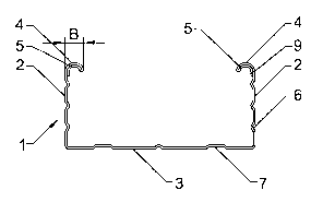
  • KNAUF, ALFONS JEAN (Allemagne)
(73) Titulaires :
  • RICHTER SYSTEM GMBH & CO. KG
(71) Demandeurs :
  • RICHTER SYSTEM GMBH & CO. KG (Allemagne)
(74) Agent: BORDEN LADNER GERVAIS LLP
(74) Co-agent:
(45) Délivré:
(86) Date de dépôt PCT: 2006-11-07
(87) Mise à la disponibilité du public: 2007-12-06
Licence disponible: S.O.
Cédé au domaine public: S.O.
(25) Langue des documents déposés: Anglais

Traité de coopération en matière de brevets (PCT): Oui
(86) Numéro de la demande PCT: PCT/EP2006/010636
(87) Numéro de publication internationale PCT: WO 2007137618
(85) Entrée nationale: 2008-11-27

(30) Données de priorité de la demande:
Numéro de la demande Pays / territoire Date
20 2006 008 668.4 (Allemagne) 2006-05-30

Abrégés

Abrégé français

L'invention concerne un profilé (1) en tôle pour la construction sèche comprenant deux sections ailes (2) et une section fond (3) reliant les sections ailes (2), un bord porteur (4) replié s'étendant dans la direction longitudinale du profilé (1) étant prévu dans au moins une section aile (2), une bande de renforcement (5) étant prévue sur le bord porteur (4) replié. Le profilé est caractérisé en ce que la bande de renforcement (5) s'étend sur toute la largeur (B) du bord porteur (4) replié.


Abrégé anglais

The invention relates to a sheet metal section (1) for dry construction, comprising two limb portions (2) and a base portion (3) that connects said limb portions (2). According to the invention, at least one of the limb portions (2) is equipped with a bent supporting edge (4) that extends in the longitudinal direction of the section (1), said bent supporting edge (4) being provided with a reinforcement strip (5). The section is characterised in that the reinforcement strip (5) extends over the entire width (B) of the bent supporting edge (4).

Revendications

Note : Les revendications sont présentées dans la langue officielle dans laquelle elles ont été soumises.


CLAIMS:
1. A sheet metal section (1) for dry construction, having two leg sections (2)
and a base
section (3) connecting the leg sections (2), a supporting edge (4) that is
bent and extends in
the longitudinal direction of the section (1) being provided on at least one
of the leg sections
(2), a reinforcing strip (5) being provided on the bent supporting edge (4),
characterized in
that the reinforcing strip (5) extends over the entire width (B) of the bent
supporting edge (4).
2. The section as recited in Claim 1,
characterized in that the reinforcing strip (5) and/or the bent supporting
edge (4) have/has
plastic material deformations (11) for fastening the reinforcing strip (5) to
the bent supporting
edge (4).
3. The section as recited in Claim 2,
characterized. in that a plurality of local plastic material deformations (11)
is provided.
4. The section as recited in Claim 2 or 3,
characterized, in that the plastic material deformations (11) have an
elongated shape and
extend in particular in the longitudinal direction of the reinforcing strip
(5).
5. The section as recited in one of Claims 2 through 4,
characterized in that the plastic material deformations (11) are created
through joining-by-
forming of the supporting edge (4) and the reinforcing strip (5), in
particular by clinching.
6. The section as recited in one of Claims 1 through 5,
characterized in that the reinforcing strip (5) is connected to the supporting
edge by adhesive
bonding.
7. The section as recited in one of Claims 1 through 6,
characterized in that the reinforcing strip (5) is a bent-back part of the leg
section (2).
8

8. The section as recited in one of Claims 1 through 6,
characterized in that the reinforcing strip (5) is a separate element, in
particular a sheet metal
strip.
9. The section as recited in one of Claims 1 through 8,
characterized in that the reinforcing strip (5) extends along the supporting
edge (4), in
particular over its entire length.
10. The section as recited in one of Claims 1 through 9,
characterized in that the reinforcing strip (5) is situated on the side of the
supporting edge (4)
facing the base section (3).
11. The section as recited in one of Claims 1 through 10,
characterized in that the supporting edge (4) has a curvature in the
transverse direction of the
supporting edge (4).
12. The section as recited in Claim 11,
characterized in that the curvature is designed in such a way that the
supporting edge (4) is
convex on the side facing away from the base section (3) and/or is concave on
the side facing
the base section (3).
13. The section as recited in Claim 12,
characterized in that the reinforcing strip (5) has a first area (8) for
contacting the supporting
edge (4) and has a second area (9) for contacting the leg section (2).
14. The section as recited in Claim 13,
characterized in that the first and second areas (8, 9) are joined together by
a bending line
(10).
15. The section as recited in Claim 13 or 14,
characterized in that the first area (8) extends parallel to the supporting
edge (4) and the
second area (9) extends parallel to the leg section (2).
9

16. The section as recited in one of Claims 1 through 15,
characterized in that the section (1) is designed as a C section.

Description

Note : Les descriptions sont présentées dans la langue officielle dans laquelle elles ont été soumises.

CA 02653635 2008-11-27
SHEET METAL SECTION FOR DRY CONSTRUCTION
[0001] The present invention relates to a sheet metal section for dry
construction.
[0002] Sheet metal sections are used in various embodiments in dry
construction. A known
embodiment of such a section is known as a C section, having two leg sections
and one base
section connecting the leg sections, a bent supporting edge extending in the
longitudinal
direction of the section being provided on each leg section.
[0003] DIN 18 182 (Part 1) in the version of January 1987 describes providing
a double
flange for the supporting edge of such a C section, this double area extending
over part of the
width of the supporting edge.
[0004] The object of the present invention is to provide a particularly stable
section with a
given thickness of material.
[0005] This object is achieved by a sheet metal section for dry construction
having two leg
sections and one base section connecting the leg sections, a bent supporting
edge extending in
the longitudinal direction of the section being provided on at least one of
the leg sections, a
reinforcing strip being provided on the bent supporting edge, extending over
the entire width
of the bent supporting edge.
[0006] The design according to the present invention allows a substantial
increase in the
stability of the section. It is thus surprisingly possible to use a thinner
sheet metal for the
section and nevertheless obtain stability values for the section that could be
achieved in the
past only by using a much thicker sheet metal. The result is a substantial
savings potential
because the use of material may be reduced significantly on the whole.
Although a somewhat
larger area of material is needed because of the reinforcing strip, this is
more than
compensated by the use of thinner sheet metal, so that on the whole, it is
possible to lower the
material consumption and thus the manufacturing cost. Another advantage is
that handling
and shipping are facilitated due to the lower weight achievable.

CA 02653635 2008-11-27
[0007] A further improvement in stability is achieved by the fact that the
reinforcing strip
and/or the bent supporting edge have/has plastic material deformations for
fastening the
reinforcing strip to the bent supporting edge. A plurality of local plastic
material deformations
may preferably be provided here.
100081 In addition, it has proven advantageous if the plastic material
deformations have an
elongated shape and extend in particular in the longitudinal direction of the
reinforcing strip.
[0009] The plastic material deformations may advantageously be created through
joining-
by-forming of leg section and reinforcing strip, in particular by clinching.
[0010] If the reinforcing strip is additionally joined with the supporting
edge by adhesive
bonding in particular, the stability of the section may be further improved.
[0011] Manufacturing of the section is simple in particular when the
reinforcing strip is a
portion of the leg section that has been bent back.
[0012] Alternatively, the reinforcing strip may be a separate element, in
particular a sheet
metal strip. In this case, a sheet metal forming step may be omitted because
the reinforcing
strip is not bent back. The reinforcing strip may instead be supplied
separately during
manufacturing and may be connected to the supporting edge, e.g., by the
plastic material
deformations.
100131 According to the present invention, it is also possible for the
reinforcing strip to
extend along the supporting edge, in particular over its entire length and/or
to be situated on
the side of the supporting edge facing the base section.
[0014] In addition, it has proven successful if the supporting edge has a
curvature in the
transverse direction of the supporting edge. This may be designed in such a
way that the
supporting edge is convex on the side facing away from the base section and/or
is concave on
the side facing the base section.
[0015] The stability is also improved by the fact that the reinforcing strip
has a first area for
contacting the supporting edge and a second area for contacting the leg
section. The first and
2

CA 02653635 2008-11-27
second areas may then be joined together by a bending line. Good support is
achieved when
the first area extends parallel to the supporting edge and the second area
extends parallel to
the leg section.
100161 According to the present invention, it may be provided that the section
is designed as
a C section.
[0017] Additional goals, features, advantages and possible applications of the
present
invention are derived from the following description of exemplary embodiments
on the basis
of the drawings. All features described and/or illustrated here, either alone
or in any
combination, constitute the subject matter of the present invention, also
independently of how
they are combined in individual claims or their reference back to preceding
claims.
[0018] Figure 1 shows a section according to the present invention in a first
embodiment
from the side;
[0019] Figure 2 shows a perspective diagram of the section from Figure 1;
[0020] Figure 3 shows a section according to the present invention in a second
embodiment
from the side;
100211 Figure 4 shows a perspective diagram of the section from Figure 3;
[0022] Figure 5 shows a section according to the present invention in a third
embodiment
from the side;
[0023] Figure 6 shows a perspective diagram of the section from Figure 5;
100241 Figure 7 shows a perspective diagram of a section according to the
present invention
in another embodiment;
[0025] Figure 8 shows a perspective diagram of a section according to the
present invention
in another embodiment;
3

CA 02653635 2008-11-27
[0026] Figure 9 shows a perspective diagram of a section according to the
present invention
in another embodiment;
[0027] Figure 10 shows a perspective diagram of a section according to the
present
invention in another embodiment.
[0028] The figures show in each case different embodiments of a section 1 of
sheet metal
for dry construction. Such a section may be used as a substructure in dry
construction, e.g., for
plasterboard in walls or suspended ceilings.
[0029] Section 1 has two leg sections 2 and a base section 3 connecting leg
sections 2. A
plurality of beads 6, 7 extending in the longitudinal direction of section 1
is shaped into leg
sections 2 and base section 3.
[0030] A bent supporting edge 4 extending in the longitudinal direction of
section 1 is
provided on each leg section 2. Supporting edge 4 pointing inward may be used
for
connecting to other fastening elements of the dry construction, e.g., using a
so-called cross
connector (not shown), which engages beneath supporting edge 4 with
protrusions provided
for this purpose.
[0031] A reinforcing strip 5 is provided on supporting edge 4, running along
supporting
edge 4 and situated on the side of supporting edge 4 facing base section 3 in
the exemplary
embodiments shown here. Reinforcing strip 5 preferably extends over entire
width B of bent
supporting edge 4.
[0032] In the embodiments shown in Figures 1, 2, 7, 8, 9 and 10, supporting
edge 4 has a
curvature running in the transverse direction of supporting edge 4 and is
designed in such a
way that supporting edge 4 is convex on the side facing away from base section
3 and is
concave on the side facing base section 3.
[0033] Whereas supporting edge 4 of the embodiments shown in Figures 1 and 2
has a
curved shape, in the design illustrated in Figures 3 and 4, supporting edge 4
is designed to be
4

CA 02653635 2008-11-27
straight and is situated at a right angle to leg section 2. In Figures 5 and
6, supporting edge 4
is situated at an acute angle to the leg section and its free end points
toward base section 3.
[0034] In the embodiments illustrated in Figures 1 through 8, reinforcing
strip 5 is a bent-
back part of leg section 2 (or of supporting edge 4), which comes to rest on
supporting edge 4.
Reinforcing strip 5 is thus folded over toward the inside during manufacturing
until it assumes
the position illustrated in Figures 1 through 8.
[0035] However, in the embodiments illustrated in Figures 9 and 10,
reinforcing strip 5 is a
separate element, e.g., in the form of a sheet metal strip, which is reliably
secured on
supporting edge 4 by material deformations 11 and/or by adhesive bonding in
the manner
described below in greater detail.
[0036] Figures 1 through 6 show that reinforcing strip 5 may have a first area
8 for
contacting supporting edge 4 and a second area 9 for contacting the inside of
leg section 2
(outside of supporting edge 4). Reinforcing strip 5 then conforms to
supporting edge 4 or leg
section 2. First and second areas 8, 9 are joined together over a bending line
10. First area 8
extends parallel to supporting edge 4 and second area 9 extends parallel to
leg section 2.
[0037] Figures 7 through 10 illustrate that reinforcing strip 5 and supporting
edge 4 may
have material deformations 11 attaching reinforcing strip 5 to supporting edge
4. A plurality
of local and locally limited material deformations 11 are formed here,
distributed over
supporting edge 4. In the embodiments shown here, material deformations 11
each have an
elongated shape and extend in the longitudinal direction of reinforcing strip
5. This
embodiment is suitable in particular within the scope of the present
invention. However,
material deformations may also be used in other forms not shown here.
Particularly great
stability is achieved when the material of supporting edge 4 and reinforcing
strip 5 flows one
into the other due to plastic material deformations 11.
[0038] Material deformations 11 may be created through joining-by-forming of
supporting
edge 4 and reinforcing strip 5. In particular the method known as clinching
may be used here.

CA 02653635 2008-11-27
[0039] As an alternative or in addition to material deformations 11,
reinforcing strip 5 may
be connected to supporting edge 4 by adhesive bonding, which results in a
particularly high
load-bearing capacity.
[0040] Section 1, which is designed as a C section, is made of curved steel
plate, in
particular galvanized. The material thickness of the sheet metal is
advantageously between
0.2 mm and 2.0 mm, in particular between 0.3 mm and 1.0 mm and preferably 0.4
mm.
6

CA 02653635 2008-11-27
List of reference numerals
1 Section
2 Leg section
3 Base section
4 Supporting edge
Reinforcing strip
6 Bead
7 Bead
8 First area
9 Second area
Bending line
11 Material deformations
B Width of the supporting edge
7

Dessin représentatif
Une figure unique qui représente un dessin illustrant l'invention.
États administratifs

2024-08-01 : Dans le cadre de la transition vers les Brevets de nouvelle génération (BNG), la base de données sur les brevets canadiens (BDBC) contient désormais un Historique d'événement plus détaillé, qui reproduit le Journal des événements de notre nouvelle solution interne.

Veuillez noter que les événements débutant par « Inactive : » se réfèrent à des événements qui ne sont plus utilisés dans notre nouvelle solution interne.

Pour une meilleure compréhension de l'état de la demande ou brevet qui figure sur cette page, la rubrique Mise en garde , et les descriptions de Brevet , Historique d'événement , Taxes périodiques et Historique des paiements devraient être consultées.

Historique d'événement

Description Date
Demande non rétablie avant l'échéance 2012-11-07
Le délai pour l'annulation est expiré 2012-11-07
Inactive : Abandon.-RE+surtaxe impayées-Corr envoyée 2011-11-07
Réputée abandonnée - omission de répondre à un avis sur les taxes pour le maintien en état 2011-11-07
Lettre envoyée 2009-03-25
Inactive : Page couverture publiée 2009-03-20
Inactive : Notice - Entrée phase nat. - Pas de RE 2009-03-18
Inactive : CIB en 1re position 2009-03-11
Demande reçue - PCT 2009-03-10
Inactive : Transfert individuel 2008-12-15
Exigences pour l'entrée dans la phase nationale - jugée conforme 2008-11-27
Demande publiée (accessible au public) 2007-12-06

Historique d'abandonnement

Date d'abandonnement Raison Date de rétablissement
2011-11-07

Taxes périodiques

Le dernier paiement a été reçu le 2010-10-26

Avis : Si le paiement en totalité n'a pas été reçu au plus tard à la date indiquée, une taxe supplémentaire peut être imposée, soit une des taxes suivantes :

  • taxe de rétablissement ;
  • taxe pour paiement en souffrance ; ou
  • taxe additionnelle pour le renversement d'une péremption réputée.

Veuillez vous référer à la page web des taxes sur les brevets de l'OPIC pour voir tous les montants actuels des taxes.

Historique des taxes

Type de taxes Anniversaire Échéance Date payée
Taxe nationale de base - générale 2008-11-27
TM (demande, 2e anniv.) - générale 02 2008-11-07 2008-11-27
Enregistrement d'un document 2008-12-15
TM (demande, 3e anniv.) - générale 03 2009-11-09 2009-10-27
TM (demande, 4e anniv.) - générale 04 2010-11-08 2010-10-26
Titulaires au dossier

Les titulaires actuels et antérieures au dossier sont affichés en ordre alphabétique.

Titulaires actuels au dossier
RICHTER SYSTEM GMBH & CO. KG
Titulaires antérieures au dossier
ALFONS JEAN KNAUF
Les propriétaires antérieurs qui ne figurent pas dans la liste des « Propriétaires au dossier » apparaîtront dans d'autres documents au dossier.
Documents

Pour visionner les fichiers sélectionnés, entrer le code reCAPTCHA :


Pour visualiser une image, cliquer sur un lien dans la colonne description du document. Pour télécharger l'image (les images), cliquer l'une ou plusieurs cases à cocher dans la première colonne et ensuite cliquer sur le bouton "Télécharger sélection en format PDF (archive Zip)" ou le bouton "Télécharger sélection (en un fichier PDF fusionné)".

Liste des documents de brevet publiés et non publiés sur la BDBC .

Si vous avez des difficultés à accéder au contenu, veuillez communiquer avec le Centre de services à la clientèle au 1-866-997-1936, ou envoyer un courriel au Centre de service à la clientèle de l'OPIC.


Description du
Document 
Date
(aaaa-mm-jj) 
Nombre de pages   Taille de l'image (Ko) 
Revendications 2008-11-27 3 73
Abrégé 2008-11-27 1 13
Dessins 2008-11-27 5 113
Description 2008-11-27 7 238
Dessin représentatif 2008-11-27 1 3
Page couverture 2009-03-20 1 35
Avis d'entree dans la phase nationale 2009-03-18 1 194
Courtoisie - Certificat d'enregistrement (document(s) connexe(s)) 2009-03-25 1 102
Rappel - requête d'examen 2011-07-11 1 119
Courtoisie - Lettre d'abandon (taxe de maintien en état) 2012-01-03 1 172
Courtoisie - Lettre d'abandon (requête d'examen) 2012-02-13 1 165
PCT 2008-11-27 4 149