Note : Les descriptions sont présentées dans la langue officielle dans laquelle elles ont été soumises.
CA 02653968 2008-11-28
METHOD OF FORMATION FRACTURE DIMENSIONS
The invention is related to the formation fracture monitoring methods and
particularly is intended to determine the dimensions of the cracks resulting
from
the formations fracturing and may be applied in oil and gas fields.
Formation fracturing is a well-known method to intensify hydrocarbons well
production by increasing producing formation bottom-hole area permeability by
means of fracturing. During the formation fracturing activities the high-
viscosity
liquid (also known as fracturing fluid) containing proppant is pumped into the
bed
in order to create a crack in the production range and fill the crack with
proppant.
To ensure efficient use the crack must be located inside the production range
and
not to protrude in the adjacent strata as well as have sufficient length and
width.
Therefore, crack dimensions determination is a critical stage to ensure
fracture
process optimization.
Currently the cracks geometry is determined using various technologies and
methods. Best known are the methods (so-called fracturing visualization),
ensuring
assessment of spatial orientation of the crack and its length during the
fracturing
activities and mostly based on localization of seismic phenomena using passive
acoustic emissions. This localization is ensured by the "cloud" of acoustic
phenomena, stating the scope within which the crack may be positioned. These
acoustic emissions are microseisms resulting from either high pre-fracture
stress
concentration, or reduction of the current stress around the crack with the
subsequent fracturing fluid flowing into the bed. At the best these phenomena
are
analyzed to obtain information of the source mechanism (energy, displacement
field, stress drop, source dimensions etc.). Upon the results of these
phenomena
analysis it is impossible to obtain direct quantitative information concerning
the
main crack. Other methods are based on measuring soil minor deformation using
CA 02653968 2010-12-07
52759-25
2
dipmeters either from the surface or from the well bore. All these methods are
rather expensive due to the necessity of proper positioning of the sensor in
the set
location accounting for the relevant mechanical grip between the bed and
instruments- Other methods ensure approximate assessment of the well crack
height based either on temperature variations or on the data obtained using
isotopic
tracers (tracer atoms). Review of the aforementioned visualization methods
above
is presented, e.g., in the following publication: Barree R.D., Fisher M.K. H
Woodroof R.A. (2002) A practical Guide to Hydraulic Fracture Diagnostic
Technologies, SPE material, paper 77442, presented at Annual Technological
Conference and Exposition in San Antonio, Texas, September 29 - October 2,
2002.
The closest analog of the method claimed is the method of bed fracture crack
dimensions determination, described in the USSR Certificate of Authorship No.
1298376, 1987, and providing injection of fracture fluid in the well bore
under
pressure enabling the said fluid creating cracks near the well and penetrate
them
and further across the crack surfaces into the bed filtration zone near the
crack, and
subsequent fluid flow parameter measurement. This method's disadvantage is the
necessity to use additional equipment and complicated calculations.
The purpose of some aspects of the invention is the creation of the method to
determine the dimensions of the crack resulting from the bed fracturing
activities
based on the analysis and simulation of the fracturing fluid pumping out after
the
bed fracturing.
An aspect of the invention relates to creating a numerical model of the
fracturing fluid pressurization from the crack and filtrate zone around the
crack
using formation fluid for the set formation parameters, fracturing data and
supposed crack dimensions in order to modify the fracturing fluid in the total
production during the well post-fracturing commissioning; during the well
startup,
throughout the entire period of the fracturing fluid ousting periodically
fluid
samples are taken from the well mouth, fracturing fluid concentration in the
CA 02653968 2010-12-07
52759-25
3
samples is measured and then the measurement results are compared with the
numerical simulation data and the crack length is determined based on ensuring
the best match of the measurement results and model calculations.
As fracturing fluid polymer fluid may be used; in this case during the
numerical model creation polymer concentration change in the ousted fracturing
fluid is also calculated as function of the time, in the fracturing fluid
samples
additionally polymer concentration is determined and, by comparing the
measurement results with the model calculations, the crack width is
determined.
Fracturing fluid may also contain an indicator allowing to differentiate it
from the formation water in case of significant amount of the formation water
present in the total production after fracturing.
In accordance with some aspects of the invention determination of the crack
dimentions,
namely - its length and width, is based on the results of the withdrawn
fracturing
fluid measurement results analyzed based on the simulation of the crack
cleaning
of the fracturing fluid. Crack cleaning is the process of ousting (withdrawal)
of the
fracturing fluid from the crack and filtrate zone around the crack using the
formation fluid. The analysis of the ousted fracturing fluid is the
measurement of
the fracturing fluid concentration in the total production as function of time
after
the fracturing, and, in case of using polymer fracturing fluid , -
concentration of the
polymer in the withdrawn fracturing fluid.
During the formation fracturing activities the fracturing fluid filtrate (or
aqueous base of the fracturing fluid, in case of using polymer fracturing
fluid)
penetrates the formation. Simultaneously, the polymer component of the
fracturing
fluid (in case of polymer fracturing fluid) is held on the formation surface
and
stays within the crack. During the well development after the fracturing the
fracturing fluid is ousted from the crack and filtrate zone near the crack
with the
filtration fluid. Thus, during the well commissioning after the fracturing
first
CA 02653968 2008-11-28
4
produced will be the fracturing fluid pumped into the formation during the
fracturing activities.
Nature of the fracturing fluid concentration in the total production as
function of time is directly determined by the process of the crack cleaning
and
filtrate area around it. Change of the ratio of the withdrawn fracturing fluid
to the
formation fluid in the total production depends on the rate of the fracturing
fluid
filtrate ousting from the filtrate zone, and, consequently, of the rate of the
formation fluid penetration in the crack (across the filtrate zone) and coming
out to
the surface. Duration of the fracturing fluid filtrate ousting from the
filtrate zone
depends on the filtrate zone depth which, in its turn, depends on the crack
length
with the set pumped in volume of the fracturing fluid. Therefore, change of
the
fracturing fluid concentration in the total production with the set well yield
depends on the crack length. Thus, with the equal total volume of the
fracturing
fluid filtrate in the filtrate zone in the early post-fracture production
period the
fracturing fluid concentration drops faster in the longer crack.
In case of using polymer fracturing fluid during the crack cleaning the
fracturing fluid filtrate also mixes with the polymer component present inside
the
crack during the fracturing fluid filtrate flowing from the filtrate zone into
the
crack. Change of the polymer (e.g., guar) concentration inside the crack and,
ultimately, in the withdrawn fracturing fluid, depends on the fracturing fluid
filtrate
inflow into the crack and on the polymer weight in the certain point inside
the
crack. On the one hand, the volume of the fracturing fluid filtrate coming
from the
filtration zone depends on the filtrate zone depth, and, consequently, on the
crack
length. On the other hand, with an equal polymer concentration along the
entire
crack volume the polymer weight distribution along the crack length is
proportional to the crack width. Therefore, the change of the polymer
concentration in the withdrawn fracturing fluid during the crack cleaning
depends
both on the crack length and width.
CA 02653968 2010-12-07
52759-25
4a
According to one aspect of the present invention, there is
provided a method for determining hydraulic fracture dimensions comprising:
creating a fracture in a borehole zone by injecting a fracturing fluid into a
wellbore,
a fracturing fluid filtrate penetrating into the formation around the fracture
through
the fracture surface and creating a filtrate zone around the fracture,
providing a
numerical model of the fracturing fluid displacement from the fracture and the
filtrate zone by a formation fluid made for given formation parameters,
fracturing
data and supposed fracture dimensions, using the model for calculating the
change of the fracturing fluid concentration in the total production during
bringing
the well into production, during bringing the well into production throughout
the
entire fracturing fluid pumping out, periodically taking produced fluid
samples from
the well mouth, measuring the recovered fracturing fluid concentration in the
taken
samples, comparing the measurement results with the model calculations and
determining the fracture length on the basis of the best match of the
measurement
results and the model calculations.
CA 02653968 2010-12-07
52759-25
Some embodiments of the invention are clarified by the drawings.
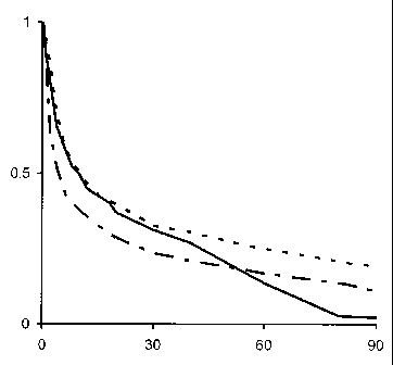
Fig. 1 shows the change of the ratio of the fracturing fluid withdrawal rate
Qf
to the total well yield Q (I-e. in effect - change of water content) as
function of
time (time t on the Ox axis is shown in hours) for typical formation
fracturing
activities in Western Siberia. Solid line corresponds with the calculation for
the
crack with the length of 150 meters and width 5 mm, dotted line - for the
crack
with the length of 150 meters and width 2.5 mm, dot-and-dash line - for the
crack
with the length of 220 meters and width 5 mm;
Fig. 2 shows the results of the calculation of polymer concentration C in the
withdrawn fracturing fluid change (in g/l) for the same dimensions as the
cracks in
Fig. 1 (time t on the Ox axis is shown in hours);
Fig. 3 shows the results of calculation and measurement of the change of
relation of the fracturing fluid withdrawal rate Qf to the total well yield Q
as
function of time (time t on the Ox axis is shown in hours);
Fig. 4 shows the results of calculation and measurement of the change of
polymer concentration C in the withdrawn fracturing fluid (in g/l) (time t on
the Ox
axis is shown in hours).
The claimed method of the formation fracture crack dimensiosn
determination is performed as follows: In the well bore fracturing fluid is
pumped
in, the fluid generally is a water-based high-viscosity fluid. The fracturing
fluid is
pumped in with the pressure sufficient to create a crack in the bottom-hole
area.
During the fracturing the fracturing fluid filtrate also penetrates the
formation
around the crack across the crack surface. The fracturing fluid may also
contain an
indicator allowing differentiating it from the formation water, in case of the
presence of the significant amount of the formation water in the total
production
after the fracturing; the indicators may be represented by non-radioactive.
chemicals widely applied to assess water spillovers (breakthroughs) between
the
wells.
CA 02653968 2008-11-28
6
In case of using polymer fracturing fluid it is critical that during the pump-
in
only water base of the fluid flows into the formation whereas the polymer
molecules due to their large size cannot penetrate the formation and stay
inside the
crack. Therefore, at the time of the production start of the fracturing fluid
back
onto the surface, the entire amount of the previously pumped-in polymer is
inside
the crack and the crack itself is surrounded by the fracturing fluid water
base.
Samples of the fluid produced are taken during the well commissioning after
performing the formation fracturing activities. Samples are taken near the
well
mouth using the method similar to the one usually applied to determine water
content. Samples are take periodically throughout the entire period of the
fracturing fluid ousting. For example, for typical post-fracturing well in
Western
Siberia the duration of the fracturing fluid withdrawal normally is 2-3 days,
over
this period product sampling is preferably made every 30 minutes during the
first
7-10 hours, then - every hour throughout the remaining time. Then the samples
are
sent to the laboratory to measure the concentration of the withdrawn
fracturing
fluid in the produced fluid and the polymer concentration (for polymer
fracturing
fluids) in the withdrawn fracturing fluid.
In the laboratory the samples are processed in a centrifuge to separate the
fracturing fluid from the oil, in the way similar to the standard water
content
measurement. It enables determination of the fracturing fluid content change
in the
total production throughout the withdrawal period reviewed. If polymer
fracturing
liquid was used, the fracturing fluid separated from the oil is analyzed to
measure
the polymer concentration. In case of using guar polymer the methodology is
based
on the known method applying phenol and sulfuric acid. As a result the
dependence of the polymer concentration in the withdrawn fracturing fluid on
the
time is obtained.
To assess the crack dimensions numerical model of the fracturing fluid ousting
from the crack and filtrate zone with the formation fluid is used (see, for
example,
CA 02653968 2008-11-28
7
Entov V.M., Turetskaya F.D., Maksimenko A.A, Skobeleva A.A. "Modeling of the
Fracturing Crack Cleaning Process", Abstracts of the Reports of the 6th
Scientific
and Practical Conference "Urgent Problems of the State and Development of
Russian Oil and Gas Industry" dedicated to the 75th Anniversary of Russian
State
Gubkin Oil and Gas University, January 26-27, 2005, Section 6 "Automation,
Modeling and Utility Supply for Oil and Gas Industry Processes", pp. 12-13).
The model calculates the change of the fracturing fluid concentration in the
produced fluid, and, in case of using polymer fracturing fluid, - change of
the
polymer concentration in the withdrawn fracturing fluid. The model input
parameters look as follows:
1. The formation permeability and porosity, formational pressure,
production interval height, formation oil viscosity.
2. Well yield or bottom-hole pressure during the fracturing fluid ousting
3. Total volume of the fracturing fluid, weight of the polymer and weight
of the proppant pumped into the formation during the fracturing activities,
the
proppant permeability and porosity, fracturing fluid viscosity.
4. Relative phase permeability values in the formation and in the pressed
proppant and the crack.
5. Supposed length and, in case of using polymer fracturing fluid, -
supposed width of the crack
The parameters stated in 1-4 must be known from the formation properties,
fracturing activities plan and data on the well productivity after holding the
fracturing activities. The crack length and width are determined by comparing
the
results of the numerical modeling and laboratory measurement of the product
samples by means of making graphs, spreadsheets or computer calculations.
The crack length and width must be selected upon the results of the best
approximation of two various data sets:
CA 02653968 2008-11-28
8
1.) Measurement of the fracturing fluid concentration in the total production
obtained from numerical calculations and measured in the laboratory,
2) Change of guar polymer concentration obtained from numerical
calculations and measured in the laboratory.
In case of the results non-alignment the supposed crack dimensions are
updated in such a way as to obtain the best approximation of the results of
the
modeling calculations and measurements using, for example, least square method
or any other mathematical quantitative method of approximation degree
assessment.
To illustrate the method proposed an example of comparing the results of
the withdrawn fluid analysis with the model calculation of the crack cleaning
after
the typical formation fracturing in Western Siberia. The laboratory analysis
of the
fracturing fluid includes measurements of the correlation of the fracturing
fluid
withdrawal rate and the total yield (i.e. water content) shown in Fig. 3 with
a solid
line and guar concentration (in g/1) in the withdrawn fracturing fluid, shown
in Fig.
4 with a solid line. The results of modeling calculations of the crack
cleaning of the
fracturing fluid for the scenario when the supposed crack geometry is taken
from
the fracturing work design obtained using typical engineering software used to
calculate the crack growth during fracturing activities, shown in Fig. 3 and 4
with a
dotted line. As we can see from Fig. 3-4 (the difference between the solid and
the
dotted lines); the measured data and the modeling results do not match very
well.
To obtain a better match of the measurement results with the modeling
calculations
(see Fig. 3-4, dot-and-dash line) the crack geometry needs to be corrected as
follows: the crack length must be increased by about 40% and the width must be
reduced by 30%. Such a correction is well aligned with the constancy of the
proppant weight inside the crack, i.e. the crack total volume remains
unchanged.
The modeled forecast results may be improved by applying indicators enabling
to
differentiate the formation water from the fracturing fluid in case of the
presence of
CA 02653968 2008-11-28
9
a substantial amount of the formation water in the total production after the
fracturing.