Note : Les descriptions sont présentées dans la langue officielle dans laquelle elles ont été soumises.
CA 02654501 2008-12-05
Specification
Video Matching Apparatus and Video Matching Method
Technical Field
The present invention relates to a video
matching apparatus and video matching method which match a
degraded video signal as an assessment target with a
reference video signal, which is identical to the degraded
video signal before degradation, on the basis of the
physical feature amount of the degraded video signal and
the reference video signal before the estimation of the
subjective quality of the degraded video signal.
Background Art
Conventionally, video quality assessment is
basically so-called subjective quality assessment, which
measures the quality perceived by a user when he/she
actually observes a video. Subjective quality assessment,
however, requires a dedicated facility and enormous time
and labor. Demands have therefore arisen for objective
assessment methods of estimating subjective qualities from
the amounts physically measured from videos to perform
video quality assessment more efficiently.
According to a conventional objective assessment
method, it suffices to handle a stable signal for
professional use, e.g., a signal for a broadcasting
CA 02654501 2008-12-05
station, as a target video signal, and only an objective
assessment algorithm is determined for standardization, as
described in, for example, reference "Objective Perceptual
Video Quality Measurement Techniques for Digital Cable
Television in the Presence of a Full Reference", ITU-T
Recommendation J.144, 2004".
For this reason, in matching processing to be
performed before the estimation of the subjective quality
of a degraded video signal, matching between the degraded
video signal and a reference video signal can be
implemented by performing the format conversion processing
of matching the format of the degraded video signal with
that of the reference video signal before degradation and
the position/synchronization matching processing of
matching the time and position of the degraded video
signal with those of the reference video signal (see, for
example, the specification of U.S. Patent No. 5,446,492).
Disclosure of Invention
Problem to be Solved by the Invention
When the quality of a video is assessed by using
a signal level (monitor signal) at which a video is
actually viewed in an environment in which, for example,
the video is viewed with a personal computer (PC), noise
or bias is sometimes added to a video signal due to
processing in the player, the characteristics/performance
- 2 -
CA 02654501 2008-12-05
of the monitor output board, or the like. Some noise or
bias cannot be perceived by human eyes and have no
influence on subjective quality. If such noise or bias
which cannot be perceived by human eyes is included as a
quality degradation factor in calculation, the quality
degradation of a video is overestimated, resulting in a
deterioration in the estimation accuracy of subjective
quality.
The present invention has been made to solve the
above problem, and has as its object to provide a video
matching apparatus and video matching method which can
remove even noise or bias added to a degraded video
signal.
Means of Solution to the Problem
A video matching apparatus of the present
invention comprises a position/synchronization matching
unit which eliminates a shift on a time axis and a
positional shift between a degraded video signal and a
reference video signal which is identical to the degraded
video signal before degradation, and a singular point
removing unit which removes a singular point as invisible
high-frequency component noise from the degraded video
signai.
In addition, a video matching apparatus of the
present invention comprises a position/synchronization
- 3 -
CA 02654501 2008-12-05
matching unit which eliminates a shift on a time axis and
a positional shift between a degraded video signal and a
reference video signal which is identical to the degraded
video signal before degradation, and a pixel value
correcting unit which removes pixel-value bias added the
degraded video signal.
A video matching method of the present invention
comprises the position/synchronization matching step of
eliminating a shift on a time axis and a positional shift
between a degraded video signal and a reference video
signal which is identical to the degraded video signal
before degradation, and the singular point removing step
of removing a singular point as invisible high-frequency
component noise from the degraded video signal.
In addition, a video matching method of the
present invention comprises the position/synchronization
matching step of eliminating a shift on a time axis and a
positional shift between a degraded video signal and a
reference video signal which is identical to the degraded
video signal before degradation, and the pixel value
correcting step of removing pixel-value bias added the
degraded video signal.
Effects of the Invention
As described above, according to the present
invention, even if noise is added to a degraded video
- 4 -
CA 02654501 2008-12-05
signal due to postprocessing in the player or the
characteristics/performance of the monitor output board,
the noise can be removed by performing the singular point
removable processing of removing a singular point as
invisible high-frequency component noise from the degraded
video signal. As a consequence, the present invention can
properly assess the quality of a degraded video signal
when the quality of a video is assessed at a signal level
(monitor signal) at which the video is actually viewed.
In addition, according to the present invention,
even if bias is added to a degraded video signal due to
post filter processing in the player or the color
correction function of the monitor output board, the bias
can be removed by performing the pixel value correction
processing of removing the pixel-value bias added to the
degraded video signal. As a consequence, the present
invention can properly assess the quality of a degraded
video signal when the quality of a video is assessed at a
signal level (monitor signal) at which the video is
actually viewed.
Furthermore, according to the present invention,
performing singular point removal processing for a
reference video signal in addition to a degraded video
signal can eliminate the adverse effect of the singular
point removal processing on subjective quality estimation
- 5 -
CA 02654501 2008-12-05
accuracy which is newly caused when the singular point
removal processing is applied to the degraded video
signal. As a consequence, it is possible to improve the
subjective quality estimation accuracy as compared with a
case in which singular point removal processing is
performed for only a degraded video signal.
In addition, the present invention outputs a
singular point removal amount as input information for a
subjective quality estimation step as a next step. With
this operation, when unexpected processing is performed in
singular point removal processing, it is possible to
consider the influences of the unexpected processing on
subjective quality estimation accuracy in the subjective
quality estimation step as the next step.
Moreover, the present invention outputs
correction information used for the correction of a pixei
value as input information for the subjective quality
estimation step as the next step. With this operation,
when unexpected processing is performed in pixel value
correction processing, it is possible to consider the
influences of the unexpected processing on subjective
quality estimation accuracy in the subjective quality
estimation step as the next step.
Brief Description of Drawings
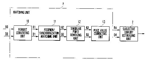
Fig. 1 is a block diagram showing the
- 6 -
CA 02654501 2008-12-05
arrangement of a video matching apparatus according to the
first embodiment of the present invention;
Fig. 2 is a flowchart showing the operation of
the video matching apparatus according to the first
embodiment of the present invention;
Figs. 3A and 3B are views for explaining the
operation of a position/synchronization matching unit in
the first embodiment of the present invention, showing the
concept of pixel matching between a reference video signal
and a degraded video signal;
Fig. 4A is a graph for explaining an example of
the operation of a singular point removing unit in the
first embodiment of the present invention, showing a frame
of a degraded video signal;
Fig. 4B is a graph for explaining an example of
the operation of the singular point removing unit in the
first embodiment of the present invention, showing the
spatial frequency of the degraded video signal;
Fig. 4C is a graph for explaining an example of
the operation of the singular point removing unit in the
first embodiment of the present invention, showing a frame
of a degraded video signal as a result of transformation
from a spatial frequency after the removal of a high-
frequency component;
Fig. 5A is a view for explaining another example
- 7 -
CA 02654501 2008-12-05
of the operation of the singular point removal processing
in the first embodiment of the present invention, showing
a 3 x 3 neighborhood averaging filter as an example of a
noise removal filter;
Fig. 5B is a view for explaining another example
of the operation of the singular point removal processing
in the first embodiment of the present invention, showing
a 3 x 3 neighborhood weight averaging filter as an example
of the noise removal filter;
Fig. 5C is a view for explaining another example
of the operation of the singular point removal processing
in the first embodiment of the present invention, showing
a cross averaging filter as an example of the noise
removal filter;
Fig. 6A is a view for explaining another example
of the operation of the singular point removal processing
in the first embodiment of the present invention, showing
a 3 x 3 neighborhood median filter as an example of the
noise removal filter;
Fig. 6B is a view for explaining another example
of the operation of the singular point removal processing
in the first embodiment of the present invention, showing
a cross median filter as an example of the noise removal
filter;
Fig. 6C is a view for explaining another example
- 8 -
CA 02654501 2008-12-05
of the operation of the singular point removal processing
in the first embodiment of the present invention, showing
a long cross median filter as an example of the noise
removal filter;
Fig. 7A is a graph for explaining the operation
of a pixel value correcting unit in the first embodiment
of the present invention, showing the influences of
processing at the time of decoding on a degraded video
signal;
Fig. 7B is a graph for explaining the operation
of the pixel value correcting unit in the first embodiment
of the present invention, showing the influences of
processing after decoding on a degraded video signal; and
Fig. 8 is a block diagram showing the
arrangement of a video matching apparatus according to the
second embodiment of the present invention.
Best Mode for Carrying Out the Invention
[First Embodiment]
The embodiments of the present invention will be
described below with reference to the accompanying
drawings. Fig. 1 is a block diagram showing the
arrangement of a video matching apparatus according to the
first embodiment of the present invention.
The video matching apparatus includes a matching
unit 1 and a subjective quality estimating unit 2. The
- 9 -
CA 02654501 2008-12-05
matching unit 1 outputs a matched reference video signal
R4 and a matched degraded video signal D4 by applying
signal processing to both an input degraded video signal
DO which has been degraded by coding or a loss in a
network and an input reference video signal RO which is
identical to the degraded video signal DO before
degradation. The subjective quality estimating unit 2
estimates the subjective quality of the matched degraded
video signal D4 by measuring the feature amounts of the
matched reference video signal R4 and matched degraded
video signal D4. Note that the apparatus in Fig. 1 forms
both a video matching apparatus and an objective video
quality assessing apparatus.
The matching unit 1 includes a format converting
unit 10, a position/synchronization matching unit 11, a
singular point removing unit 12, and a pixel value
correcting unit 13. Fig. 2 is a flowchart showing the
operation of the video matching apparatus.
The format converting unit 10 performs the
format conversion processing of matching the format of the
reference video signal RO with that of the degraded video
signal DO (step S10 in Fig. 2).
The position/synchronization matching unit 11
performs the position/synchronization matching processing
of eliminating the shift on the time axis and positional
- 10 -
CA 02654501 2008-12-05
shift between a reference video signal R1 and a degraded
video signal Dl, which have been subjected to signal
processing by the format converting unit 10 (step Sll in
Fig. 2).
The singular point removing unit 12 performs the
singular point removal processing of removing a singular
point (noise) from the a degraded video signal D2
subjected to signal processing by the
position/synchronization matching unit 11 (step S12 in
Fig. 2). Note that the singular point removing unit 12
also performs singular point removal processing for a
reference video signal R2 for the following reason.
The pixel value correcting unit 13 performs the
pixel value correction processing of removing the bias
(pixel-value bias) added to a reference video signal R3
subjected to signal processing by the singular point
removing unit 12 (step S13 in Fig. 2).
The operation of the matching unit 1 in each
processing will be described in detail below. The format
converting unit 10 converts the degraded video signal DO
to match the format of the degraded video signal DO with
that of the reference video signal RO, when the signal
format, size, and aspect ratio of the reference video
signal RO differ from those of the degraded video signal
DO. If, for example, the reference video signal RO is in
- 11 -
CA 02654501 2008-12-05
the uncompressed YUV format and the degraded video signal
DO is in the uncompressed RGB format, it suffices to
convert the degraded video signal DO by using the
conversion formula defined by ITU-R (International
Telecommunications Union Radiocommunication Sector)
recommendation BT-601 "STUDIO ENCODING PARAMETERS OF
DIGITAL TELEVISION FOR STANDARD 4:3 AND WIDE-SCREEN 16:9
ASPECT RATIOS". Note that if the degraded video signal DO
is in the compressed format, it is necessary to convert
the format into an uncompressed format in advance.
If the size or aspect ratio of the reference
video signal RO differs from that of the degraded video
signal DO, the format converting unit 10 converts the
degraded video signal DO to match its size or aspect ratio
with that of the reference video signal RO. If the sizes
or aspect ratios of the reference video signal RO and
degraded video signal DO are in an integer multiple
relationship, calculations can be performed with a simple
integer multiple. If, however, they are not in an integer
multiple relationship, it is necessary to convert the size
of the degraded video signal DO to an arbitrary size. In
this case, it suffices to convert the size to an arbitrary
size as in image resolution conversion described in
chapter 7 of reference "Easy-to-Understand Digital Image
Processing - from Filter Processing to DCT & Wavelet", CQ
- 12 -
CA 02654501 2008-12-05
publishing Co., 1996. Note that if the luminance
occurrence range or color occurrence range of the
reference video signal RO differs from that of the
degraded video signal DO because of the difference in
format between the reference video signal RO and the
degraded video signal DO, matching processing is also
performed to match their occurrence ranges with each
other, as needed.
In order to match the pixel positions of the
frame of the reference video signal R1, subjected to
format conversion by the format converting unit 10, with
those of the degraded video signal Dl, the
position/synchronization matching unit 11 obtains the
difference values between a target frame DF of the
degraded video signal Dl and a target frame RF of the
reference video signal R1 shown in Fig. 3A. At this time,
as shown in Fig. 3B, the position/synchronization matching
unit 11 obtains the total sum of the difference values
between the respective pixels of the target areas of the
frames RF and DF while shifting the target area of the
target frame DF of the degraded video signal Dl which
corresponds to the target area of the target frame RF of
the reference video signal R1 with coordinates R(l, 1) of
the target frame RF being located at the upper left of the
target area. Referring to Fig. 3B, each square of the
- 13 -
CA 02654501 2008-12-05
frames RF and DF represents a pixel.
The position/synchronization matching unit 11
shifts the target area of the degraded video signal Dl
such that coordinates D(l, 1), D(l, 2), D(l, 3), D(2, 1),
D(2, 2), D(2, 3), D(3, 1), D(3, 2), and D(3, 3) each are
located at the upper left of each target area, and obtains
the total sum of the difference values between the
respective pixels of each of the target areas and the
target area of the reference video signal Rl. Referring
to Fig. 3B, reference symbol Al denotes a target area with
the coordinates D(l, 1) located at the upper left; A2, a
target area with the coordinates D(2, 2) located at the
upper left; and A3, a target area with the coordinates
D(3, 3) located at the upper left.
Upon obtaining the total sum of the difference
values between the respective pixels of the current target
frame RF of the reference video signal Rl and the target
frame DF of the degraded video signal Dl, the
position/synchronization matching unit 11 obtains the
total sum of the difference values between the respective
pixels (the total sum of the difference values between the
respective pixels will be abbreviated as a difference
value hereinafter) of a new target frame RF which is
adjacent to the above target frame RF and the target frame
DF of the degraded video signal Dl. The
- 14 -
CA 02654501 2008-12-05
position/synchronization matching unit 11 obtains the
difference values between one target frame DF of the
degraded video signal Dl and a plurality of target frames
RF of the reference video signal Rl for each frame FR and
each target area of the target frame DF, and outputs the
reference video signal R2 and the degraded video signal D2
in a matched state to the singular point removing unit 12,
with the state in which the difference values are
minimized being a state in which the reference video
signal Rl is matched most with the degraded video signal
Dl (the times and positions are matched).
The singular point removing unit 12 receives the
reference video signal R2 and the degraded video signal D2
which have been subjected to position/synchronization
matching processing by the position/synchronization
matching unit 11, and removes a singular point as
invisible high-frequency component noise from the degraded
video signal D2. This singular point is noise independent
of compression/decompression which is added due to
postprocessing in the player or the
characteristics/performance of the monitor output board.
Figs. 4A to 4C are graphs for explaining an
example of the operation of the singular point removing
unit 12, showing an example of high-frequency component
removal processing for the degraded video signal D2.
- 15 -
CA 02654501 2008-12-05
Referring to each of Figs. 4A and 4C, the abscissa is the
X-axis, and the ordinate is the Y-axis. Referring to Fig.
4B, the abscissa represents a horizontal frequency Fl, and
the ordinate, a vertical frequency F2. The horizontal
frequency Fl gradually decreases in the left direction,
and gradually increases in the right direction. The
vertical frequency F2 gradually decreases in the lower
direction, and gradually increases in the upper direction.
The singular point removing unit 12 converts
entirely or partly the frame of the degraded video signai
shown in, for example, Fig. 4A into a spatial frequency as
shown in Fig. 4B by a two-dimensional Fourier transform or
the like, and removes a high-frequency component HF. The
singular point removing unit 12 then performs an inverse
two-dimensional Fourier transform to restore the degraded
video signal as shown in Fig. 4C, thereby removing a
singular point U from the degraded video signal.
Alternatively, letting X(m, n) be the value of a
target pixel in the frame of a degraded video signal, the
singular point removing unit 12 obtains a value Y(m, n) of
the same target pixel after the removal of a singular
point according to the following equation and removes the
singular point.
i=k j=1
Y(m, n) Y X(m + i, n + j) W (i, j) . . . (1)
i=-k j=-I
- 16 -
CA 02654501 2008-12-05
where W(i, j) represents a filter function.
Assuming k = 1 = 1 as values implementing the calculation
of equation (1), the 3 x 3 neighborhood averaging filter
shown in Fig. 5A, the 3 x 3 neighborhood weight averaging
filter shown in Fig. 5B, the cross averaging filter shown
in Fig. 5C, and the like are conceivable.
The 3 x 3 neighborhood averaging filter is
applied to the central pixel of 3 pixels in the horizontal
direction x 3 pixels in the vertical direction in Fig. 5A
as a target pixel, and obtains a value Y(m, n) of the
target pixel by setting a filter function W(i, j) of each
pixel as shown in Fig. 5A. Likewise, the 3 x 3
neighborhood weight averaging filter is designed to obtain
the value Y(m, n) of a target pixel by setting the filter
function W(i, j) as shown in Fig. 5B. The cross averaging
filter is applied to the central pixel of a cross
comprising five pixels as a target pixel, and obtains the
value Y(m, n) of the target pixel by setting the filter
function W(i, j) of each pixel as shown in Fig. 5C.
In addition, as a filter for implementing the
calculation of equation (1), the 3 x 3 neighborhood median
filter shown in Fig. 6A, the cross median filter shown in
Fig. 6B, or the long cross median filter shown in Fig. 6C
can be used. The 3 x 3 neighborhood median filter is
applied to the central pixel of 3 pixels in the horizontal
- 17 -
CA 02654501 2008-12-05
direction x 3 pixels in the vertical direction in Fig. 6A
as a target pixel, and obtains the median of nine pixel
values as the value Y(m, n) of the target pixel. The
cross median filter is applied to the central pixel of a
cross comprising five pixels in Fig. 6B as a target pixel,
and obtains the median of the five pixel values as the
value Y(m, n) of the target pixel. The long cross median
filter is applied to the central pixel of a cross
comprising nine pixels in Fig. 6C as a target pixel, and
obtains the median of the nine pixel values as the value
Y(m, n) of the target pixel.
Note that a degraded video signal D3 subjected
to signal processing by the singular point removing unit
12 is identical to the degraded video signal D2 before it
is input to the singular point removing unit 12 except
that another degradation is added. If, therefore, subject
quality is estimated by using the degraded video signal D3
subjected to signal processing by the singular point
removing unit 12 and the reference video signal R2 not
subjected to signal processing, the estimation accuracy
deteriorates. For this reason, the singular point
removing unit 12 performs the same signal processing as
that for the degraded video signal D2 with respect to the
reference video signal R2 input from the
position/synchronization matching unit 11 to remove a
- 18 -
CA 02654501 2008-12-05
singular point. This makes it possible to derive a proper
assessment value when the subjective quality estimating
unit 2 estimates subjective quality in the subsequent
steps.
As filters used by the singular point removing
unit 12, various types of low-pass filters are
conceivable. The examination made by the present inventor
revealed that it was proper to use the cross median filter
in Fig. 6B for singular point removal processing. This
was because an optimal estimation accuracy could be
obtained in consideration of the calculation amount, which
is not very large, and a combination of more schemes and
devices.
In order to remove the bias added to a degraded
video signal, the pixel value correcting unit 13 obtains
the relationship between the pixels of the reference video
signal R3 subjected to singular point removal processing
by the singular point removing unit 12 and the
corresponding pixels of the degraded video signal D3, and
corrects the pixel values of the degraded video signal D3
so as to match the pixel values of the degraded video
signal D3 with the pixel values of the reference video
signal R3 as a whole. A bias is added to the degraded
video signal D3 due to, for example, decoding processing
in the player, post-filter processing after decoding, or
- 19 -
CA 02654501 2008-12-05
the color correction function of the monitor output board.
The pixel value correcting unit 13 obtains the
relationship between the pixel values of the reference
video signal R3 and the corresponding pixel values of the
degraded video signal D3, as shown in Figs. 7A and 7B.
Fig. 7A shows the influences of processing at the time of
decoding on a degraded video signal, and is a graph
obtained by plotting the relationship between the pixel
values of a reference video signal and those of a degraded
video signal after going through post-filter processing in
the player, with the abscissa representing a luminance DL
of the degraded video signal, and the ordinate, a
luminance value RL of the reference video signal. In the
case shown in Fig. 7A, the relationship between the pixel
values of the reference video signal and the corresponding
pixel values of the degraded video signal is represented
by a second-order regression equation.
Fig. 7B shows the influences of processing after
decoding on a degraded video signal, and is a graph
obtained by plotting the relationship between the pixel
values of a reference video signal and those of a degraded
video signal after going through the color correction
function of the monitor output board. In the case shown
in Fig. 7B, the relationship between the pixel values of
the reference video signal and the corresponding pixel
- 20 -
CA 02654501 2008-12-05
values of the degraded video signal is represented by a
first-order regression equation.
The pixel value correcting unit 13 derives a
regression equation from the relationship between the
pixel values of the reference video signal R3 and the
corresponding pixel values of the degraded video signal
D3, and corrects the pixel values of the degraded video
signal D3 by using the regression equation. The pixel
value correcting unit 13 outputs the reference video
signal R3 input from the singular point removing unit 12
as the matched reference video signal R4 to the subjective
quality estimating unit 2, and also outputs the degraded
video signal D3, whose pixel values are corrected, as the
matched degraded video signal D4 to the subjective quality
estimating unit 2. As a regression equation to be derived
by the pixel value correcting unit 13, a linear
expression, a quadratic expression, a polynomial, an
exponential function, a log function, or a combination
thereof is conceivable. According to the examination made
by the present inventor, in many cases, the above
operation was implemented by approximation using a
quadratic expression. In this case, therefore, the
regression is performed by using a quadratic expression.
In this embodiment, the degraded video signal D3 is
matched with the reference video signal R3. However, it
- 21 -
CA 02654501 2008-12-05
suffices to correct the pixel values of the reference
video signal R3 by matching the reference video signal R3
with the degraded video signal D3.
The subjective quality estimating unit 2
estimates the subjective quality of a degraded video
signal by measuring the feature amounts of the matched
reference video signal R4 and matched degraded video
signal D4 (step S14 in Fig. 2). An example of the
subjective quality estimating unit 2 is disclosed in, for
example, reference "Okamoto, Hayashi, Takahashi, and
Kurita, "Proposal for an objective video quality
assessment method that takes spatio-temporal feature
amounts into consideration", THE TRANSACTIONS OF THE
IEICE, Vol. J88-B, No. 4, pp. 813 - 823, 2005".
As described above, according to this
embodiment, providing the singular point removing unit 12
makes it possible to remove even noise added to a degraded
video signal due to postprocessing in the player or the
characteristics/performance of the monitor output board.
In addition, according to the embodiment, providing the
pixel value correcting unit 13 makes it possible to remove
even bias added to a degraded video signal due to post-
filter processing in the player or the color correction
function of the monitor output board. As a consequence,
the embodiment can properly assess the quality of a
- 22 -
CA 02654501 2008-12-05
degraded video signal.
[Second Embodiment]
The second embodiment of the present invention
will be described next. Fig. 8 is a block diagram showing
the arrangement of a video matching apparatus according to
the second embodiment of the present invention. The same
reference numerals as in Fig. 1 denote the same components
in Fig. 8.
A singular point removing unit 12a of a matching
unit la of this embodiment operates in the same manner as
the singular point removing unit 12 of the first
embodiment, and outputs a singular point removal amount S
(e.g., the sum of pixel value change amounts before and
after the removal of a singular point from a degraded
video signal - the sum of pixel value change amounts
before and after the removal of a singular point from a
reference video signal) in singular point removal
processing as input information to a subjective quality
estimating unit 2.
A pixel value correcting unit 13a operates in
the same manner as the pixel value correcting unit 13 of
the first embodiment, and outputs correction information C
(e.g., a regression equation or coefficients of a
regression equation) in pixel value correction processing
as input information to the subjective quality estimating
- 23 -
CA 02654501 2008-12-05
unit 2.
With this operation, when the subjective quality
estimating unit 2 performs subjective quality estimation
processing, it is possible to inform the subjective
quality estimating unit 2 of the degree of matching
processing so as to allow the subjective quality
estimating unit 2 to consider how much a degraded video
signal is changed by matching processing by the matching
unit la. The first embodiment gives no consideration to
the removal of a singular point which can be perceived by
human eyes or the correction of pixel values. However,
when the singular point removing unit 12 or the pixel
value correcting unit 13 performs unexpected processing,
the operation may influence subjective quality estimation
processing by the subjective quality estimating unit 2.
For this reason, this embodiment allows the subjective
quality estimating unit 2 to consider unexpected
processing by informing the subjective quality estimating
unit 2 of the degree of matching processing.
Note that the video matching apparatuses of the
first and second embodiments can be implemented by a
computer including a CPU, a storage device, and an
interface for external devices and programs which control
these hardware resources. Programs for making such a
computer to implement the video matching method of the
- 24 -
CA 02654501 2008-12-05
present invention are provided while being recorded on a
recording medium such as a flexible disk, CD-ROM, DVD-ROM,
or memory card. The CPU writes the programs read out from
the recording medium into the storage device, and executes
the processing described in the first and second
embodiments in accordance with the programs.
Industrial Applicability
The present invention can be applied to an
objective video quality assessment technique of estimating
subjective quality by measuring the physical feature
amount of a video signal.
- 25 -