Note : Les descriptions sont présentées dans la langue officielle dans laquelle elles ont été soumises.
CA 02654972 2008-12-10
WO 2008/005239 PCT/US2007/014819
TWIN BLOWERS FOR GAS SEPARATION PLANTS
Related Applications
[0001] This application is a continuation-in-part of
U.S. Ser. No. 11/477,908, filed June 30, 2006.
Technical Field
[0002] The present invention relates to canceling
pressure pulsations and consequently induced noise
during the operation of blowers of the type used in gas
separation systems.
Background of the Invention
[0003] Non-cryogenic gas separation processes,
especially adsorptive processes, are used to separate
various components from a gaseous mixture, e.g., oxygen
from air. Pressure swing adsorption (PSA) processes,
including superatmospheric adsorption/desorption
processes, subatmospheric vacuum swing adsorption (VSA)
and transatmospheric vacuum pressure swing adsorption
(VPSA) processes have been used for decades for air
separation and are well known in the art.
[0004] Conventional PSA, VSA and VPSA processes
employ positive displacement blowers for either fluid
feed into or exhaustion from the adsorbent vessel.
Large tonnage gas separation plants, including VPSA
plants, require high flow of gas in and out of
adsorption beds. Commercially available off-the-shelf
blowers cannot supply the required flow of air into the
plant, and custom-made blowers in this size range
become prohibitively expensive. In addition, larger
blowers generate higher pressure pulses in the plant
CA 02654972 2008-12-10
WO 2008/005239 PCT/US2007/014819
- 2 -
that might damage the equipment and lead to louder
noise levels.
[0005] In VPSA plants, blowers displace a large
quantity of gas from inlet on the intake side to outlet
on the discharge side at relatively constant volume via
pockets between the lobes of each blower and the
housing. The flow of gas in and out of a blower is not
steady, rather it is a discrete action. Due to
pressure differences between the gas pockets and
piping, every time the rotor tips clear the housing, it
causes pressure fluctuations. Such fluctuations create
pressure pulsations. These pulsations are a function
of blower size and speed. Within the piping and plant
equipment, these pulsations manifest themselves as
vibrations, which shake the piping and plant equipment
and can result in severe damage. In ambient air, these
pulsations manifest as noise, which can be extremely
loud. As the demand for higher throughput out of these
plants increases, the size of the plant and the size of
the blowers in the plant increase. However, larger
blower sizes and higher rotation speeds create higher
pulsations, which could be detrimental to plant
equipment such as the after-cooler, beds and pipes, and
may also generate higher noise levels. Generally, the
most damaging pulsations are generated at low
frequency. The primary frequency of the pulsations
generated by the blowers is the lowest frequency in the
frequency spectrum, which makes it extremely
challenging to cancel these pulsations.
[0006] To minimize the impact of the pulsations, gas
separation plants may utilize blower inlet and/or
discharge silencers. However, such silencers become
CA 02654972 2008-12-10
WO 2008/005239 PCT/US2007/014819
- 3 -
prohibitively expensive for larger plants, and they
decrease plant efficiency by inducing pressure drop in
the flow. Even though these silencers can reduce the
pulsations and noise, nonetheless, the pulsation
problem is still present and needs to be eliminated by
some other means.
[0007] Prior attempts to solve the pulsation and
noise problem include the installation of a Helmholtz-
type pulsation dampener, also known as a Helmholtz
resonator (U.S. Patent No. 5,957,664), cylindrical
metal shell discharge silencers (U_S. Patent Nos.
5,957,664 and 5,658,371), and underground type concrete
silencers (U.S. Patent No. 6,451,097). In particular,
cylindrical metal shell type silencers are widely used
in the industry, but they are not very effective for
use with high amplitude and low frequency pulsations.
In order to improve their effectiveness, it has been
suggested that cylindrical metal shell type silencers
be used in conjunction with a Helmholtz resonator (U.S.
Patent No. 5,957,664). However, these resonators are
only effective in cancelling pulsations at certain
frequencies. These silencing methods are based on
reactive and absorptive sound cancellation principles.
The biggest hurdle in designing a large gas separation
plant is that it requires a much higher flow rate which
can only be achieved either by using a single larger
than commercially available blower or two smaller off-
the-shelf blowers simultaneously. U.S. Patent No.
5,656,068 disclosed a four-bed VPSA process, operated
as two pairs of 2-bed systems, referred to as 2x2
cycle/system, to produce oxygen from air. Each pair of
beds is operated 180 out of phase and the two pairs of
CA 02654972 2008-12-10
WO 2008/005239 PCT/US2007/014819
- 4 -
beds are operated out of phase by one-half of a half-
cycle. Two compressors (one Roots or positive
displacement and one centrifugal) and two vacuum pumps
(one Roots or positive displacement and one
centrifugal) are used and one of the two compressors is
periodically in the idle or vent mode. Although the
use of two relatively small blowers instead of one
large blower has been disclosed in U.S. Patent No.
5,656,068, the active noise cancellation concept is not
taught or used.
[0008] U.S. Patent Application No. 11/395,140
(Attorney Docket No. D-21491) disclosed another
approach that employs a silencer for reducing noise
level to about 90 dB level at the discharge of the
vacuum blower in large tonnage oxygen VPSA plants. The
silencer comprises reactive chambers to attenuate low
frequency pulsations and absorptive chambers to
attenuate medium to high frequency noise. Outer and
interior walls of the silencer are made of concrete.
Unlike steel-shelled silencers, the concrete silencer
will not vibrate or act as a noise source. The low
frequency noise is cancelled by expanding and
contracting flow in series of reactive chambers that
have multiple openings in the dividing walls. The
absorptive chambers enforce a serpentine flow, and
their entire interior walls are covered with sound
absorbing material to effectively cancel noise at high
frequencies. However, this approach still requires the
use of a large custom-made blower or multiple blowers
to provide a sufficient feed gas supply.
[0009] Thus, there is a continuing need for-low cost
and reliable solutions to prevent pulsation damage and
CA 02654972 2008-12-10
WO 2008/005239 PCT/US2007/014819
- 5 -
reduce noise levels while providing high flow of gas in
and out of the plant in a cost effective manner.
Summary of the Invention
[0010] The present invention relates to a method of
reducing or eliminating pressure pulsations and
resulting noise created by blowers in a gas separation
plant. More specifically, the present invention is
directed to a method of canceling pressure pulsations
from operating blowers in a gas separation plant
comprising: (a) installing two identical blowers, each
having an intake side and a discharge side; (b)
connecting the first blower to a first conduit and the
second blower to a second conduit; (c) positioning the
first conduit and second conduit symmetrically; (d)
merging the first conduit with the second conduit into
a single merged conduit; and (e) synchronizing the
first blower with the second blower, wherein the first
blower generates pressure pulsations at a targeted
frequency that are 1800 out of phase with the pressure
pulsations at the same targeted frequency generated by
the second blower.
[0011] The method employs two identical blowers
synchronized to generate 180 out of phase pressure
pulsations. In this way, the blowers provide both a
large flow of air and active cancellation of pressure
pulsations. The two blowers are attached to a common
shaft with a phase shift in such a way that pressure
pulses created by one blower will actively be cancelled
by the pulses generated by the other blower. At the
same time, both blowers will work together to force a
large quantity of gas flow in or out of the plant. The
CA 02654972 2008-12-10
WO 2008/005239 PCT/US2007/014819
- 6 -
twin set of blowers can be used for feed or vacuum
applications in the plant. This way large tonnage gas
separation plant capital costs can be reduced by
eliminating the need for an expensive silencer and a
single large custom-made blower.
[0012] The known silencing methods are only
effective at a certain frequency range. In this
invention, twin blowers cancel the pressure pulsations
at the primary frequency of each blower at their
source. Pulsations at higher harmonics of primary
frequency may persist and may need to be cancelled
using a conventional silencer. However, pressure
pulsations at primary frequency of the blower have the
most damaging energy and are harder to attenuate as
compared to higher harmonics of this frequency. From
this point of view, it is more efficient and economical
to eliminate the low frequency pulsations in the plant
immediately after they are generated using the twin
blower concept described herein than to try to cancel
them using silencers after they have already developed
in the piping.
[0013] The present invention is also directed to a
gas separation system comprising: (a) two identical
blowers, each having an intake side and a discharge
side; (b) a first conduit connected to the first blower
and a second conduit connected to the second blower,
where the first conduit and second conduit are
positioned symmetrically; (c) a merged conduit into
which the first conduit and the second conduit merge
together; and (d) a mechanism which synchronizes the
first blower with the second blower, wherein the first
blower generates pressure pulsations at a targeted
CA 02654972 2008-12-10
WO 2008/005239 PCT/US2007/014819
- 7 -
frequency that are 1801 out of phase with the pressure
pulsations at the same targeted frequency generated by
the second blower.
[0014] The present invention is further directed to
an apparatus for canceling pressure pulsations produced
in a gas separation process wherein such apparatus
simultaneously provides either feed gas or evacuates
product gas, comprising: (a) two identical blowers,
each having an intake side and a discharge side; (b) a
first conduit connected to the first blower and a
second conduit connected to the second blower, where
the first conduit and second conduit are positioned
symmetrically; (c) a merged conduit into which the
first conduit and the second conduit merge together;
and (d) a mechanism which synchronizes the first blower
with the second blower, wherein the first blower
generates pressure pulsations at a targeted frequency
that are 180 out of phase with the pressure pulsations
at the same targeted frequency generated by the second
blower.
Brief Description of the Drawings
[0015] For a more complete understanding of the
present invention and the advantages thereof, reference
should be made to the following Detailed Description
taken in conjunction with the accompanying drawings in
which:
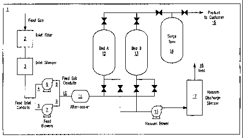
[0016] FIG. 1 is a schematic of the layout of a VPSA
Plant.
[0017] FIG. 2 is a schematic of the twin-blower
system and cancellation of pressure pulsations.
CA 02654972 2008-12-10
WO 2008/005239 PCT/US2007/014819
- 8 -
[0018] FIG. 3 is an illustration showing pressure
fields in the blower piping.
[0019] FIG. 4 is an illustration showing
cancellation of pressure pulsations as shown in the
simulation results, where the piping geometry is
symmetrical and the generated pressure pulsations are
1800 out of phase. No pulsations are present in the
piping after the blower conduits are merged.
[0020] FIG. 5 is an illustration showing that the
pressure pulsations are not cancelled when the
pulsations are not completely out of phase and the
piping geometry is symmetrical. Pulsations are present
in the piping after the blower conduits are merged.
[0021] FIG. 6 is an illustration showing out of
phase pulsations are not cancelled when the piping is
asymmetrical. Pulsations are present in the exit
piping after the blower exit conduits are merged.
[0022] FIG. 7 is an illustration showing
computational fluid dynamics (CFD) simulation results
confirming flows coming from each blower successfully
merging into the merged piping for the given volumetric
flow.
[0023] FIG. 8 is an illustration showing a different
pipe configuration (Y-shaped), which is also successful
in canceling pulsations, and showing that no pulsations
are present in the piping after the blower conduits are
merged.
[0024] FIG. 9 is an illustration showing a typical
blower and a blower conduit.
[0025] FIG. 10 is a schematic of a twin-blower
system.
CA 02654972 2008-12-10
WO 2008/005239 PCT/US2007/014819
- 9 -
Detailed Description of the Invention
[0026] The present invention relates to a method of
reducing or eliminating pressure pulsations and
resulting noise generated by blowers in a gas
separation plant. The term "pressure pulsations" may
be used interchangeably with the terms "pressure
pulses", "gas pulsations", "gas pulses", "pulsations"
or "pulses". The term "conduit" may be interchangeably
used with the terms "pipe" or "piping". The method
employs two identical or twin blowers synchronized to
generate pulsations that are 180 out of phase. Twin
blowers provide both a large flow of air and active
cancellation of pressure pulsations at the primary
frequency of the blowers. In one embodiment, the two
blowers are tied to a common shaft with a phase shift
in such a way that pressure pulses created by one
blower will actively be cancelled by the pulses
generated by the other blower. At the same time, both
blowers will work together to force a large quantity of
gas flow in or out of the plant. The twin set of
blowers cam be used for feed or vacuum applications in
the plant. In this way, capital costs of a gas
separation plant can be reduced by eliminating the need
for one or more expensive silencers and a single large
custom-made blower.
[0027] FIG. 1 shows the layout of a VPSA plant (1).
In this particular plant layout, the twin blowers are
feed blowers, but the same concept can equally be
applied to vacuum blowers. During the feed step, feed
gas enters into the plant through inlet filter (2) and
inlet silencer (3). Silenced feed gas is supplied to
two feed blowers (6, 7) through feed inlet conduits (4,
CA 02654972 2008-12-10
WO 2008/005239 PCT/US2007/014819
- 10 -
5). Each feed blower discharges the feed gas to its
respective conduit (8, 9) and after which the merged
flow (10) is cooled in an after-cooler (11) before
entering into one of the adsorbent beds (12, 13) where
one or more components of the gas is adsorbed and the
remaining product gas component is discharged to a
surge tank (14) through which it is delivered to the
customer (15). While one of the adsorbent beds is
going through the feed (adsorption) step, the other bed
is regenerated with a vacuum (desorption) step, during
which rejected gas is vacuumed out of the adsorption
beds through vacuum blower (16) and silenced in the
vacuum discharge silencer (17) before vent (18) out to
atmosphere. The concept of vacuum pressure swing
adsorption (VPSA) cycle and plant are described in U.S.
Patent No. 6,010,555 in more detail. FIG. 1
illustrates a two-bed plant, but the present invention
is also effective in plants having more than two beds.
[0028] To reduce unwanted pulsations in the plant,
this invention uses a twin set of blowers to actively
cancel pressure pulsations generated by one blower with
pulsations generated by the other blower. The present
invention is applicable to conventional off-the-shelf
blowers of any size. FIG. 2 focuses on the twin feed
blowers and their piping in the VPSA plant. Conduits
(8, 9) of the first blower (6) and the second blower
(7) are merged to a single conduit (10) and both
blowers work together to force large quantities of gas
into the plant. In one embodiment, blowers are
actuated by the same electric motor (20), while one of
the blowers is directly connected to the shaft (21) of
the electric motor and the other one is actuated
CA 02654972 2008-12-10
WO 2008/005239 PCT/US2007/014819
- 11 -
through a timing belt (22) attached to this shaft. A
timing belt ensures a constant phase shift between
blowers in such a way that generated pulses from the
blowers are completely reversed (i.e., 1800 out of
phase). Other methods of creating a constant phase
shift include, but are not limited to, mechanisms such
as gears or chains. As gas forced by each blower flows
through their respective exit conduits (8, 9), pressure
pulsation waves develop in these conduits. The
pulsations from each blower interfere and eventually
cancel each other when two blower exit conduits merge
(10). This is the underlying concept of active
pulsation cancellation and it is applicable to any
blower size and speed. FIG. 2 illustrates the piping
on the discharge side of the twin blowers, but the
present invention is also directed to the piping on the
intake side of the blowers. The conduits on either or
both the intake and discharge sides of the blowers may
be symmetrically placed to achieve active pulsation
cancellation. In other embodiments, the first blower
may be indirectly connected to the second blower. For
example, each blower may be directly connected to a
separate motor, and the motors are linked and timed to
rotate the blowers at the appropriate phase shift.
[0029] The present invention is directed to a method
of canceling pressure pulsations from operating blowers
in a gas separation plant comprising: (a) installing
two identical blowers, each having an intake side and a
discharge side; (b) connecting the first blower to a
first conduit and the second blower to a second
conduit; (c) positioning the first conduit and second
conduit symmetrically; (d) merging the first conduit
CA 02654972 2008-12-10
WO 2008/005239 PCT/US2007/014819
- 12 -
with the second conduit into a single merged conduit;
and (e) synchronizing the first blower with the second
blower, wherein the first blower generates pressure
pulsations at a targeted frequency that are 180 out of
phase with the pressure pulsations at the same targeted
frequency generated by the second blower. The present
invention contemplates canceling pressure pulsations at
a particular targeted frequency that can be selected
based on the length of the first and second conduits.
Generally, the targeted frequency will be at the
primary frequency of the pressure pulsations generated
by the blowers.
[0030] The present invention is also directed to a
gas separation system comprising: (a) two identical
blowers, each having an intake side and a discharge
side; (b) a first conduit connected to the first blower
and a second conduit connected to the second blower,
where the first conduit and second conduit are
positioned symmetrically; (c) a merged conduit into
which the first conduit and the second conduit merge
together; and (d) a mechanism which synchronizes the
first blower with the second blower, wherein the first
blower generates pressure pulsations at a targeted
frequency that are 180 out of phase with the pressure
pulsations at the same targeted frequency generated by
the second blower.
[0031] The present invention is further directed to
an apparatus for canceling pressure pulsations produced
in a gas separation process wherein such apparatus
simultaneously provides either feed gas or evacuates
product gas, comprising: (a) two identical blowers,
each having an intake side and a discharge side; (b) a
CA 02654972 2008-12-10
WO 2008/005239 PCT/US2007/014819
- 13 -
first conduit connected to the first blower and a
second conduit connected to the second blower, where
the first conduit and second conduit are positioned
symmetrically; (c) a merged conduit into which the
first conduit and the second conduit merge together;
and (d) a mechanism which synchronizes the first blower
with the second blower, wherein the first blower
generates pressure pulsations at a targeted frequency
that are 1800 out of phase with the pressure pulsations
at the same targeted frequency generated by the second
blower.
[0032] FIG. 9 illustrates a typical blower such as
blower 1 (6), wherein there is a discharge side having
a discharge flange (33). The pulses are generated due
to the action of rotating lobes inside the blowers, and
it is assumed that the associated waves start traveling
at the centerline of the blower (32). The centerline
(32) divides the blower into equal parts, with the
discharge side on one side of the centerline and the
intake side on the other. The frequency of these
pulses is directly related to revolution speed of the
blower drive shaft and number of lobes in the blower.
The wavelength of these pulses is simply the ratio of
speed of sound to frequency of pulsations. To prevent
acoustic resonances from developing in the piping
circuit that connects the blower to other equipment in
the plant, the pipe lengths should be selected
carefully by comparing them with the wavelength of the
pulsations. For example, for the case of a single pipe
connecting blower to a silencer, the blower-side end of
the pipe is treated as a closed-end as the pressure
pulses start to travel at this end, and silencer-side
CA 02654972 2008-12-10
WO 2008/005239 PCT/US2007/014819
- 14 -
end of the pipe is treated as an open-end as the pipe
opens into a much larger volume. Quarter-wavelength
(2~/4) resonances develop in this pipe with one end
closed and the other end open. For this reason, in
order to prevent acoustic resonances in the piping it
is required that the distance from the blower
centerline (i.e., where the waves start to travel) to
the open-end of the connecting pipe is not equal to any
integer multiple of a quarter-wavelength of a targeted
frequency or its higher harmonics.
[0033] Referring to FIG. 9, the distance from the
blower centerline (32) to discharge flange (33) is
called length A. The length of the conduit (34) from
blower discharge (33) to the end of the conduit (35),
i.e., as shown in FIG. 10 where the two conduits (8, 9)
merge at a merging point (40) is called length B.
Then, the total length of A+B should be selected in
such a way that it does not promote quarter-wavelength
resonances to develop in the piping. In other words,
A+B should not be equal to any integer multiple of a
quarter-wavelength of a targeted frequency or its
higher harmonics.
[0034] The length A varies depending on the size of
the blower. As an example, the length A is roughly 9-
inches for small test unit size blowers and reaches
up to 35-39 inches for the largest commercial size
blowers. Blowers in VPSA plants typically operate at
frequencies in the range of 40-10oHz, and the
corresponding wavelengths for this range of frequencies
are in the range of 10-30 feet. Since the length A can
be comparable with the wavelengths mentioned here, it
is crucial to include this length into the pipe length
CA 02654972 2008-12-10
WO 2008/005239 PCT/US2007/014819
- 15 -
for calculations to prevent acoustic resonances. FIG.
9 shows the discharge conduit (34) as a straight pipe,
but the discharge conduit (34) may be L-shaped or
angled to form a Y-shape with the discharge conduit
from the second blower, e.g., the discharge conduits
(8, 9) shown in FIGS. 2, 3 and 10. FIG. 9 illustrates
the blower and piping on the discharge side of a
blower, but the present invention is also directed to
the piping on the intake side of a blower. In the case
of piping on the intake side, measurement of length A
would be from the centerline to the intake flange and
length B would be the length of the intake piping.
[0035] Referring to FIG. 10, blower 1 (6) is
connected to a discharge conduit (8) and blower 2 (7)
is connected to a discharge conduit (9). These two
discharge conduits (8, 9) connect into a single merged
pipe (10) at the merging point (40). Each of the
discharge conduits (8, 9) extends from the blower
discharge to the merging point (40), and merged pipe
(10) extends from the merging point (40) to an after-
cooler for a feed blower configuration or to a silencer
for a vacuum pump configuration. FIG. 10 illustrates
"L"-shaped conduits as an example that the conduit (34)
of FIG. 9 does not have to be a straight pipe and may
be configured as conduit (8) and that the end of the
conduit (35) is the merging point (40). FIG. 10
illustrates the piping on the discharge side of the
twin blowers, but the present invention is also
directed to the piping on the intake side of the
blowers.
A0036] It is very important to analyze the twin
blower piping circuit to utilize this technology
CA 02654972 2008-12-10
WO 2008/005239 PCT/US2007/014819
- 16 -
successfully. The acoustical modes and natural
frequencies of the piping should be identified to
prevent acoustic resonances from developing in piping
circuit.. In the vicinity of resonance frequencies,
the amplitude of pulsations is amplified and pulsation
cancellation becomes less effective. In addition,
depending on the frequency, different mode shapes may
be established in the conduits (8, 9).
[0037] There are two distinct acoustical mode shapes
that may develop in the conduits (8, 9) for the twin
blowers. Some of these mode shapes present identical
pressure fields in both conduits and they are
identified herein as "symmetrical modes". On the other
hand, there are other mode shapes in which the pressure
field in one conduit is completely the opposite of the
pressure field of other conduit, and they are
identified herein as "asymmetrical modes". The
symmetrical and asymmetrical modes are further
described below:
A. Symmetrical Modes:
[0038] In symmetrical modes, the pressure
pulsations in both of the blower conduits (8, 9) up to
the merging point (40) are identical to each other.
To determine acoustic natural frequencies, the
distance from the blower centerline (32) to the
discharge end of the merged pipe (10) should be used
in the calculations. This distance should include
length A from blower centerline (32) to blower
discharge flange (33), plus the length B from the
blower discharge flange (33) to the merging point (40)
plus the length of the merged pipe (10). If the
conduits are situated on the intake side of the
CA 02654972 2008-12-10
WO 2008/005239 PCT/US2007/014819
- 17 -
blower, then the distance should be the distance from
the blower centerline (32) to the blower intake
flange, plus the length of the intake conduit, plus
the length of the merged intake pipe. As the conduits
(8, 9) are identical to each other, either one can be
used in the calculations. As the blower induces
closed-end conditions on the blower end of the conduit
(34) and the merged pipe (10) exit has open-end
boundary conditions, quarter-wavelength (A/4) acoustic
resonances develop in the piping. The natural
frequencies for symmetrical modes (fns) are given by
the following equation:
fs=(2n-1) c 4L where n=1, 2, 3... (Equation 1)
b
Lb is the distance from blower centerline through the
blower conduit (either 8 or 9) to the end of the
merged pipe (10) and c is the speed of sound. In
order to prevent acoustical resonances from developing
in the conduits (8, 9) and merged pipe (10), the
distance from centerline of the blower (32) to the end
of the merged pipe (10) should not be equal to any
integer multiple of a quarter-wavelength of a targeted
frequency or its higher harmonics.
B. Asymmetrical Modes:
L0039] For asymmetrical modes developed in the
piping, the pressure.pulsations in one of the blower
conduits (8) is completely the opposite of the
pressure pulsation in the other blower conduit (9).
In addition, there exists a zero pressure condition at
the merging point (40), with no pressure pulsations
CA 02654972 2008-12-10
WO 2008/005239 PCT/US2007/014819
- 18 -
present in the merged pipe (10) from merging point
(40) to the end of the merged pipe. As there exists
no pressure pulses in the merged pipe, only acoustic
natural frequencies and modes of the conduits that
connect blower 1 (6) to blower 2 (7) should be
analyzed. To determine acoustic natural frequencies,
the distance from centerline of one of the blowers,
through the attached blower conduit to the end of the
conduit should be used in the calculations. For
example, for blower 1 (6), this distance should be the
distance from the blower centerline (32) to the blower
discharge flange (33) plus the length of the conduit
(8) from the discharge flange (33) to the merging
point (40). If the conduits are situated on the
intake side of the blower, then the distance should be
the distance from the blower centerline (32) to the
blower intake flange plus the length of the intake
conduit.
[0040] As the blowers induce closed-end boundary
conditions and open-end boundary conditions are
present at the merging point (40), quarter-wavelength
(N/4) acoustic resonances develop in blower discharge
conduits. The natural frequencies for asymmetrical
modes (fi.) are given by the following equation:
f (2n -1) c 4Lr where n=1, 2, 3.._, (Equation 2)
Lt is the distance from centerline of the blower 1 (6)
through the first conduit (8) to the merged point (40)
and c is the speed of sound. In order to prevent
acoustical resonances from developing in the conduits
connecting one blower to the other, the distance from
the centerline of blower 1 (6) through the conduit (8)
CA 02654972 2008-12-10
WO 2008/005239 PCT/US2007/014819
- 19 -
to the merged point (40) should not be equal to any
integer multiple of a quarter-wavelength of a targeted
frequency or its higher harmonics.
Example 1: Theoretical analysis
[0041] Pressure fields in the blower exit conduits
(8, 9) are identified as shown in FIG. 3. The analysis
showed that if the exit piping geometry is symmetric
and the waves are completely out of phase, the pressure
pulses in the merged exit piping (10) are completely
diminished. In the analysis, the origin x= y= O(where
x is the horizontal axis measuring the horizontal leg
of the exit conduit of each blower and y is the
perpendicular axis measuring the length of the merged
exit conduit) is located where the two exit conduits
(8, 9) meet, and distance from the 900 turn to the
origin is set to L on each side.
[0042] The analysis is as follows:
Pressure pulsations in the exit conduit (8) of the
first blower (6) are due to pulses generated by the
first blower. The pressure field in this conduit has
two components, namely incident pressure Pi,z and its
reflection Pj, these pressure components are defined
as:
PI = A1 -e'k' and P,, = B, e''kY (Equation 3)
where Ai and B,, are the amplitude of pressure
pulsations and k is the wave number and is defined as:
CA 02654972 2008-12-10
WO 2008/005239 PCT/US2007/014819
- 20 -
k = ~ = 2~c f (Equation 4)
where c is the wave speed, and A and f are the
wavelength and frequency of the pulsations,
respectively.
Similarly, incident and reflected pressures in the exit
conduit (9) of the second blower (7) are defined as:
PZ = A2 = e'k' and P,.a = Ba = e-'ky (Equation 5)
where A2 and B2 are the amplitude of pressure
pulsations.
The transmitted portion of the incident pressure waves
after the 900 turns in the exit conduits (8, 9) on each
side can be expressed as
Prt = C, = elk(x+L) and Pa = CZ = e-'k(s-' ) (Equation 6)
where Cl and C2 are the amplitude of pressure
pulsations.
Using Equations 3, 4 and 5, the pressure at both
turning points in the exit conduits is expressed as:
at x=-L and y= 0, P,.l+ P,, = Põ + P2 =>A,+ B,= C,+ CZ = e21kL
(Equation 7)
at x=L and y=0, P.2+P,Z=PZ-}'Pl=>AZ+B2=CZ+Cl =ezikL
(Equation 8)
CA 02654972 2008-12-10
WO 2008/005239 PCT/US2007/014819
- 21 -
Also using Equation 5, pressure in the horizontal pipe
can be expressed as:
P=Põ +PZ =C, =e'k(x+L) + C2 =e``k("-c) (Equation 9)
At x=O and y=O, where the two exit conduits merge,
Equation 6 reduces to:
P=(C, +CZ) -ek` (Equation 10)
Combining Equations 6 and 7 and then factoring the
common terms will yield:
A, +B, +AZ +BZ
C, +C2 = l+e2ikL (Equation 11)
Since the waves are completely out of phase, then
A, = -AZ and B, _ -Ba (Equation 12)
If Equation 12 is plugged into Equation 11, C,+ C2
reduces to zero, then pressure equation (Equation 8)
also goes to zero at the point where two pipes are
merged. Therefore the pressure in the merged exit
piping (10) Pf will be equal to zero at all times.
This is because the pipe dimensions on each branch is
identical and the pressure pulsations in conduits (8,
9) are 180 out of phase.
CA 02654972 2008-12-10
WO 2008/005239 PCT/US2007/014819
- 22 -
Example 2: Validation
[0043] A finite element analysis of blower pipe exit
conduit was performed using commercial finite element
code ANSYS 5.7. As shown in FIG. 3, only exit piping
from the two blowers to inlet of after-cooler is
modeled. Pressure fields inside the exit conduits are
investigated for various geometries and pulsation
frequencies from 10 Hz to 500 Hz. Corresponding
wavelengths of this frequency span are in the range of
2 ft to 125 ft for the temperature ranges of interest,
i.e., 70 F to 300 F and wave speed in air. It is also
important to note that in a typical VPSA plant, the
pulsation frequency is most likely in the range of 40
Hz to 100 Hz, but it could be as high as 250 Hz. From
this point of view, typical pulsation frequencies
comfortably fall into the frequency range used in the
simulations. In the model, the effect of the blower is
entered as pressure boundary and the shape of the
pressure profile is assumed to be sinusoidal. In
addition, due to ax.isymmetric nature of the pipe
geometry, only a 2-dimensional model was developed to
save computational time and effort.
[0044] In the simulations, the blower exit pipes
were 12 inches in diameter, "L"-shaped (i.e., having a
90 bend) and 5 feet in length on each side of the "L"
before merging with each other. In the simulations,
different conduit lengths were tested for the piping
connection from blower discharge to the point both
pipes merge. It is observed that there is no effect of
pipe length on the pulsation levels of the final merged
pipe as the pulsations are always cancelled by each
other after the pipes are merged as long as the
CA 02654972 2008-12-10
WO 2008/005239 PCT/US2007/014819
- 23 -
conduits are symmetric and the pressure pulsations are
1800 out of phase. Similarly, simulations performed
with different excitation frequencies (i.e., different
wavelengths) yielded cancelled waves in the merged pipe
when the conditions stated above were satisfied.
However, the level of pulsations in the conduits before
they merge depends on pipe length and excitation
frequency. To prevent excessive pressure pulses from
developing in the conduits, pipe lengths should be
carefully selected, so that the frequency of pressure
pulsations does not coincide with acoustic resonance of
the pipe and put the pipe into resonance. The length
of the conduits should not be equal to any integer
multiples of quarter-wavelength for the primary
pulsation frequency or its higher harmonics in order to
prevent quarter-wavelength resonances from developing
in the conduits before the waves interfere with each
other.
[0045] As the conduits merge with each other, the
pulses generated by the first blower interfere with the
pulses generated by the second blower and eventually
the pulses cancel each other if the symmetry and 180
out of phase pressure conditions are met, as shown in
FIG. 4. Canceling of pressure pulsations with pressure
pulsations from another source is a successful means of
reducing such pulsations, particularly at low
frequencies. It is.important to maintain the symmetry
of the piping so that when the pulsations from the
first blower interfere with the pulsations from the
second blower, the two sets of pulsations are
completely (i.e., 180 ) out of phase and they cancel
each other out. If the pressure pulses are not
CA 02654972 2008-12-10
WO 2008/005239 PCT/US2007/014819
- 24 -
completely out of phase as shown in FIG. 5, or the
piping configuration is not totally symmetric as shown
in FIG. 6, simulations show that pressure pulsations
are not cancelled at the merged conduit. For these
reasons, the key factor for effective pulsation
cancellation is to have an all-around symmetric unit,
in which the blowers and piping must be identical in
dimension, geometry and material properties.
Example 3: Flow characteristics
[0046] It is also important to investigate the flow
characteristics of the exit conduits as the flow
mechanics are completely different than the wave
mechanics in the piping. Directing the opposing waves
to each other can effectively cancel them but from a
fluid mechanics point of view, directing two flows
straight to each other may result in vortex formation
and higher pressure drop in the piping. For this
reason a computational fluid dynamics simulation of the
pipe circuit was performed using commercial
computational fluid dynamics software ANSYS/CFX. In
this model, the same pipe length and diameter are used
as in the wave model and simulations. Each blower was
assumed to provide an extremely high flow rate of
40,000 scfm of air for a 12-inch diameter pipe. The
flow rate was intentionally selected to be high to
investigate the flow field under very high flows. FIG.
7 illustrates the effective and homogenous mixing of
the flow from the two conduits without forming a vortex
at these extreme flow cases, therefore, there should be
no flow issues at these or any lower velocities.
CA 02654972 2008-12-10
WO 2008/005239 PCT/US2007/014819
- 25 -
[0047] The invention described herein is discussed
in the context of feed blowers. However, the twin
blower concept is equally applicable for vacuum
applications. In fact, it is more crucial to use twin
blowers in a vacuum application since the largest
amount of gas per unit time is displaced during the
vacuum step. The need for a larger blower and
silencing the corresponding higher pulses are amplified
during the vacuum step.
[0048] Positive displacement rotary compressors can
be divided into following groups: (a) straight lobe,
including 2-lobe and 3-lobe; (b) screw (helical)
compressors, including 3+4 and 4+6; (c) sliding vane
compressors, including 6, 8, or 10 vane or even higher
numbers can be used. The present invention can work
with any type of blower with any number of blower lobes
as long as both blowers have the same number of lobes.
Having the same internal geometry and same number of
lobes in each of the twin blowers will guarantee that
the pulses generated by the first blower will be
identical to pulses generated by the second blower.
For the case of two-lobe blowers, by geometry, there
are four pockets in the blower. In one full 360
rotation of the drive shaft, four pockets are
discharged by the blower, and hence four pressure
pulses are generated for one full rotation of the drive
shaft. Therefore, pressure pulsations complete on full
cycle for every 90 rotation of the drive shaft. For
'this reason, to generate completely out of phase
pulsations, two-lobe blowers should be 45 out of
phase. Similarly, in the case of three-lobe blowers,
there are six pockets in the blower. In one full
CA 02654972 2008-12-10
WO 2008/005239 PCT/US2007/014819
- 26 -
rotation of the drive shaft, six pockets are discharged
by the blower, and hence six pressure pulses are
generated by one full rotation of the drive shaft.
Therefore, pressure pulsations complete one full cycle
for every 60 rotation of the drive shaft. For this
reason, to generate completely out of phase pressure
pulsations, the blowers should be operated 30 out of
phase to cancel pulsations. As an example, for a
typical 900 rpm motor speed in a VPSA plant, the
frequency of drive shaft rotation is 15 Hz (900 rpm).
A two-lobe blower generates pulsations at four times
the frequency of the drive shaft and a three-lobe
blower generates pulsations at six times the frequency
of the drive shaft. Thus, a two-lobe blower operating
at 900 rpm will generate pressure pulsations at a
primary frequency of 60 Hz, and a three-lobe blower
operating at 900 rpm will generate pressure pulsations
at a primary frequency of 90 Hz:
[0049] Different pipe configurations were tested to
observe the effect of pipe configuration on wave
interference. Instead of the preferred L-shaped
piping, straight piping coming from the blowers and
forming a Y-shape after they merge were tested and
yielded successful results as shown in FIG. 8. It is
observed that as long as the piping is symmetric, any
piping geometry will work to achieve wave cancellation.
[0050] Pressure pulsations start to develop at the
discharge point of each blower and they only cancel
after pulsations from both blowers interfere with each
other. For this reason, the use of a Helmholtz
resonator may be necessary to prevent the pressure
pulsations from developing at the conduit of each
CA 02654972 2008-12-10
WO 2008/005239 PCT/US2007/014819
- 27 -
blower before the conduits are merged at the junction
point. Pulsations are particularly amplified as one of
.the acoustic resonance frequencies of the piping
coincides with the blower frequency or its harmonics.
Helmholtz resonators are very effective for canceling
pressure pulses at certain frequencies. Placing one or
more such resonators at the exit of each blower before
merging the two pipes will eliminate any pulsations at
specific frequencies before they are developed in these
pipes to further reduce pressure pulsations. These one
or more resonators may also be placed on the intake
side of each blower. It is very crucial to place these
resonators symmetrically so that they will not distract
from active cancellation of the pressure pulses at the
primary frequency generated by the blowers.
[0051] From a technical point of view, the most
effective way of canceling pulsations and plant noise
is to attenuate the pulsations at its source. The
present invention utilizes the concept of active
pulsation cancellation by interfering same-amplitude
1800 out of phase waves immediately after they are
generated. Active pulsation cancellation provided by
twin blowers eliminates the most damaging low frequency
pulsations at the blowers' primary frequency. From
this point of view, active pulsation cancellation is
always preferable over reactive and/or absorptive
silencers as they are not as effective to attenuate low
frequency pulsations. Furthermore, elimination of
pulsations right after they are discharged from the
blower means less stress on and more reliability of the
plant piping and equipment.
CA 02654972 2008-12-10
WO 2008/005239 PCT/US2007/014819
- 28 -
[0052] In another embodiment of the invention, the
conduits positioned on the intake side of the blowers
are also symmetrical and merge into one merged conduit
and may be used in combination with Helmholtz
resonators and/or silencers.
[0053] Smaller blowers create pulses with smaller
amplitudes as compared to pulses generated by a much
larger blower, as pulse amplitude is directly related
to blower size. From this point of view, using twin
blowers generates smaller pulsations and are therefore
less of a problem than a single large blower.
[0054] A typical VPSA plant is equipped with feed
blower inlet and vacuum blower discharge silencers to
eliminate unwanted noise and pulsation in the plant.
As the plant size gets larger, the size and cost of
such silencer increases as well. Sometimes a Helmholtz
resonator is employed in addition to the silencer as
the silencer by itself is insufficient to attenuate the
high level of blower pulsations. This invention
eliminates the need for costly large silencers. Gas
separation processes using one or more beds can use
this invention for either supplying feed gas to the
beds or for evacuating the beds.
[0055] High gas pulsations are also an important
concern for equipment reliability in gas separation
plants. In the past, many failures were due to gas
pulsations generated by blowers. A twin set of blowers
will eliminate potentially damaging high gas pulsations
and, as a result, will increase plant reliability.
[0056] This invention also eliminates the need for
costly and custom-made large blowers. The twin blowers
concept utilizes two relatively small and commercially
CA 02654972 2008-12-10
WO 2008/005239 PCT/US2007/014819
- 29 -
available blowers to provide a large flow of air into
the plant. The prohibitively expensive alternative to
this approach is to custom build a blower that produces
double the flow of each small blower. Besides being
expensive, such large blowers produce very high
pulsations, and silencing such pulsations becomes a
costly and challenging task.
[0057] Although the invention has been described in
detail with reference to certain preferred embodiments,
those skilled in the art will recognize that these are
other embodiments within the spirit and the scope of
the claims.