Sélection de la langue

Search

Sommaire du brevet 2655631 

Énoncé de désistement de responsabilité concernant l'information provenant de tiers

Une partie des informations de ce site Web a été fournie par des sources externes. Le gouvernement du Canada n'assume aucune responsabilité concernant la précision, l'actualité ou la fiabilité des informations fournies par les sources externes. Les utilisateurs qui désirent employer cette information devraient consulter directement la source des informations. Le contenu fourni par les sources externes n'est pas assujetti aux exigences sur les langues officielles, la protection des renseignements personnels et l'accessibilité.

Disponibilité de l'Abrégé et des Revendications

L'apparition de différences dans le texte et l'image des Revendications et de l'Abrégé dépend du moment auquel le document est publié. Les textes des Revendications et de l'Abrégé sont affichés :

  • lorsque la demande peut être examinée par le public;
  • lorsque le brevet est émis (délivrance).
(12) Demande de brevet: (11) CA 2655631
(54) Titre français: SYSTEMES DE FOURNITURE ET DE DETECTION DE DOPANTS
(54) Titre anglais: DOPANT DELIVERY AND DETECTION SYSTEMS
Statut: Réputée abandonnée et au-delà du délai pour le rétablissement - en attente de la réponse à l’avis de communication rejetée
Données bibliographiques
(51) Classification internationale des brevets (CIB):
  • G01N 27/64 (2006.01)
(72) Inventeurs :
  • CROUCH, GRAHAM (Royaume-Uni)
  • GOWERS, JONATHAN MARCEL (Royaume-Uni)
(73) Titulaires :
  • SMITHS DETECTION-WATFORD LIMITED
(71) Demandeurs :
  • SMITHS DETECTION-WATFORD LIMITED (Royaume-Uni)
(74) Agent: SMART & BIGGAR LP
(74) Co-agent:
(45) Délivré:
(86) Date de dépôt PCT: 2007-06-12
(87) Mise à la disponibilité du public: 2007-12-27
Licence disponible: S.O.
Cédé au domaine public: S.O.
(25) Langue des documents déposés: Anglais

Traité de coopération en matière de brevets (PCT): Oui
(86) Numéro de la demande PCT: PCT/GB2007/002160
(87) Numéro de publication internationale PCT: GB2007002160
(85) Entrée nationale: 2008-12-17

(30) Données de priorité de la demande:
Numéro de la demande Pays / territoire Date
0612047.1 (Royaume-Uni) 2006-06-17

Abrégés

Abrégé français

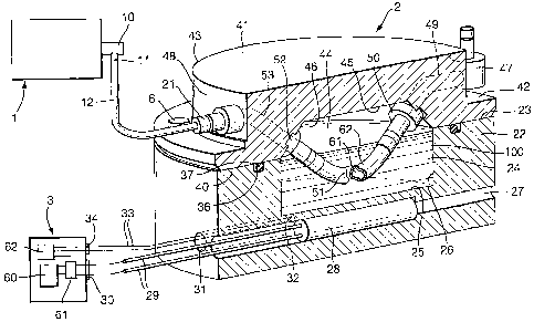
L'invention concerne un spectromètre à mobilité d'ions (1) ou un autre appareil de détection auquel est relié un réservoir externe de dopants (22, 41, 24, 44). Le réservoir présente une base en acier inoxydable (22) avec un creux (24), un appareil de chauffage (28) et un détecteur de température (32). Le dispositif de chauffage (28) et le détecteur (32) sont reliés à un contrôle de température (3) à rétroaction pour maintenir une température constante du dopant liquide (100) dans le creux (24). Un couvercle (41) est scellé autour de la surface supérieure (23) de la base (22) et supporte les extrémités opposées d'une longueur d'un tube perméable à la vapeur (51) qui est rabattu vers le bas de manière à ce qu'une partie de sa longueur soit immergée dans le dopant. Une extrémité du tube (51) est reliée à l'IMS (1) et l'autre extrémité s'ouvre sur l'extérieur de manière à ce que l'air puisse être amené par tube vers l'IMS et puisse collecter la vapeur de dopant qui traverse la paroi du tube.


Abrégé anglais

An ion mobility spectrometer (1) or other detection apparatus has an external dopant reservoir (22, 41, 24, 44) connected to it. The reservoir has a stainless steel base (22) with a recess (24), a heater (28) and a temperature sensor (32). The heater (28) and sensor (32) are connected to a feedback temperature control (3) to maintain a constant temperature of liquid dopant (100) in the recess (24). A lid (41) is sealed around the upper surface (23) of the base (22) and supports opposite ends of a length of vapour-permeable tubing (51) that is bent down so that a part of its length is immersed in the dopant. One end of the tubing (51) is connected with the IMS (1) and the other end opens externally so that air can be supplied along the tubing to the IMS and collect dopant vapour passed through the wall of the tubing.

Revendications

Note : Les revendications sont présentées dans la langue officielle dans laquelle elles ont été soumises.


7
CLAIMS
1. Dopant delivery apparatus including a reservoir (22, 41, 24, 44) containing
a supply
of dopant chemical (100), characterised in that a gas passage (49, 61, 53)
extends
through the apparatus, that the gas passage has a wall (62) along at least a
part of its
length exposed to the contents (100) of the reservoir (22, 41, 24, 44), the
wall (62)
being permeable to vapour of the dopant (100), that the gas passage (49, 61,
53) is
adapted to be connected at one end to a pneumatic circuit (12, 11, 10) of
detection
apparatus (1), and that the apparatus includes a heater (28) for heating the
chemical
(100) in the reservoir (22, 41, 24, 44), and a sensor (32) for deriving an
indication of
the temperature of the chemical in the reservoir.
2. Dopant delivery apparatus according to Claim 1, characterised in that the
dopant
chemical is a liquid (100).
3 Dopant delivery apparatus according to Claim 1 or 2, characterised in that
the gas
passage (61) is provided at least in part by a tube (51) having a vapour-
permeable
wall (62).
4. Dopant delivery apparatus according to Claim 3, characterised in that the
wall (62) of
the tube (51) is of PTFE.
5. Dopant delivery apparatus according to Claim 3 or 4, characterised in that
a part at
least of the length of the tube (51) is immersed in the chemical (100).
6. Dopant delivery apparatus according to any one of the preceding claims,
characterised in that the reservoir includes a base (22) with a recess (24)
containing
the dopant chemical (100) and a lid (41) sealed with the base and enclosing
the recess
(24).
7. Dopant delivery apparatus according to Claim 6 dependent on any one of
Claims 3 to
5, characterised in that the tube (51) is attached with the lid (41), and that
opposite

8
ends of the tube (51) communicate with respective inlet and outlet passages
(49 and
53) extending through the lid (41).
8. Dopant delivery apparatus according to Claim 6 or 7, characterised in that
the heater
(28) is located in the base (22) below the recess (24).
9. Dopant delivery apparatus according to any one of Claims 6 to 8,
characterised in
that the temperature sensor (32) is located in the base (22) below the recess
(24).
10. Dopant delivery apparatus according to Claim 9, characterised in that the
heater (28)
and temperature sensor (32) are located in respective different bores (27 and
31) in
the base (22).
11. Dopant delivery apparatus according to any one of the preceding claims,
characterised in that the apparatus includes a feedback temperature control
(3)
arranged to control energisation of the heater (28) in response to the output
of the
sensor (32) such as to maintain a substantially constant temperature of the
dopant
chemical (100).
12. Dopant delivery apparatus according to any one of the preceding claims,
characterised in that the reservoir (22, 41, 24, 44) is of stainless steel.
13. Dopant delivery apparatus including a reservoir (22, 41, 24, 44)
containing a dopant
chemical (100), characterised in that a gas passage (49, 61, 53) extends
through the
apparatus, that the gas passage has a wall (62) along at least a part of its
length
exposed to the contents (100) of the reservoir (24, 44), the wall (62) being
permeable
to vapour of the dopant (100), that the gas passage (49, 61, 53) is arranged
to supply
dopant vapour to detection apparatus (1), and that the apparatus includes a
temperature control unit (3) arranged to maintain a substantially constant
temperature
of the chemical (100) in the reservoir (24, 44).

9
14. A detection system including detection apparatus (1) and dopant delivery
apparatus
(2, 3) according to any one of the preceding claims, characterised in that the
dopant
delivery apparatus (2, 3) is separate from and connected with the detection
apparatus
(1).
15. A detection system according to Claim 14, characterised in that the
detection
apparatus (1) includes an ion mobility spectrometer.

Description

Note : Les descriptions sont présentées dans la langue officielle dans laquelle elles ont été soumises.


CA 02655631 2008-12-17
WO 2007/148045 PCT/GB2007/002160
DOPANT DELIVERY AND DETECTION SYSTEMS
This invention relates to dopant delivery apparatus of the kind including a
reservoir
containing a supply of dopant chemical.
Field ion mobility detection instruments (IMS) often include provision for
chemical
doping by which a known, small quantity of a known vapour is added to the
pneumatic circuit.
The doping vapour produces a known response in the instrument, called the
Resident Ion Peak
(RIP), which functions as a reference point. Existing dopant sources are
usually housed in small
cylindrical tubes within the detection instrument. When heated, these sources
permeate vapour
at a low concentration into the pneumatic circuit of the detector. This
relatively crude
arrangement means that the dopant concentration varies considerably.
Where an IMS instrument is used to detect Non-Traditional Agents, it is usual
to apply
additional heat to specific parts of the pneumatic circuit. The side-effect of
this increased
temperature is to increase the amount of dopant delivered, which, as well as
altering dopant
concentration, causes the supply of dopant to be exhausted more rapidly.
Typically, the existing
dopant sources will only sustain continuous doping in these circumstances for
a few months.
It is an object of the present invention to provide altemative dopant delivery
apparatus
and detection systems.
According to one aspect of the present invention there is provided dopant
delivery
apparatus of the above-specified kind, characterised in that a gas passage
extends through the
apparatus, that the gas passage has a wall along at least a part of its length
exposed to the
contents of the reservoir, the wall being permeable to vapour of the dopant,
that the gas passage
is adapted to be connected at one end to a pneumatic circuit of detection
apparatus, and that the
apparatus includes a heater for heating the chemical in the reservoir, and a
sensor for deriving
an indication of the temperature of the chemical in the reservoir.

CA 02655631 2008-12-17
WO 2007/148045 PCT/GB2007/002160
2
The dopant chemical is preferably a liquid. The gas passage is preferably
provided at
least in part by a tube having a vapour-permeable wall, such as of PTFE. A
part at least of the
length of the tube may be immersed in the chemical. The reservoir preferably
includes a base
with a recess containing the dopant chemical and a lid sealed with the base
and enclosing the
recess. The tube is preferably attached with the lid, opposite ends of the
tube communicating
with respective inlet and outlet passages extending through the lid. The
heater may be located in
the base below the recess and the temperature sensor may be located in the
base below the
recess. The heater and temperature sensor are preferably located in respective
different bores in
the base. The apparatus preferably includes a feedback temperature control
arranged to control
energisation of the heater in response to the output of the sensor such as to
maintain a
substantially constant temperature of the dopant chemical. The reservoir may
be of stainless
steel.
According to another aspect of the present invention there is provided dopant
delivery
apparatus including a reservoir containing a dopant chemical, characterised in
that a gas
passage extends through the apparatus, that the gas passage has a wall along
at least a part of its
length exposed to the contents of the reservoir, the wall being permeable to
vapour of the
dopant, that the gas passage is arranged to supply dopant vapour to detection
apparatus, and that
the apparatus includes a temperature control unit arranged to maintain a
substantially constant
temperature of the chemical in the reservoir.
The dopant delivery apparatus may be separate from and connected with the
detection
apparatus. The detection apparatus may include an ion mobility spectrometer.
A detection system including dopant delivery apparatus according to the
present
invention will now be described, by way of example, with reference to the
accompanying
drawing, which is a perspective cross-sectional view of the apparatus.

CA 02655631 2008-12-17
WO 2007/148045 PCT/GB2007/002160
3
The system includes detection apparatus in the form of an ion mobility
spectrometer
IMS 1, a dopant delivery module 2 externally of the IMS, and a temperature
control unit 3. The
units are not drawn to scale in the drawing.
The IMS 1 is entirely conventional and will not be described here. It has an
inlet 10 at
one end for analyte gas or vapour to be detected and a dopant inlet 11
adjacent the analyte inlet,
which is connected via tubing 12 to an outlet coupling 21 on the dopant
delivery module 2. The
dopant could be supplied to the IMS 1 at different locations, as is well known
in IMS
instruments.
The dopant delivery module 2 is generally cylindrical with a circular shape
when viewed
from above. The lower part of the module 2 is formed by a base body 22 of
stainless steel or
other suitable material which is resistant to the chemical dopant being used.
The upper face 23
of the base body 22 has a centrally-located, circular well or recess 24
extending down to about
half the height of the base. The well 24 has a flat floor 25 and an aimular
wall 26, both
uninterrupted by any apertures or openings. The well 24 contains a quantity
100 of dopant
chemical, such as ammonia or acetone, in a liquid or solid form, such as a
powder. A bore 27
extends through the body 22 across its diameter, just below the floor 25 of
the well 24. The bore
27 contains an electrical resistance heating element 28 positioned centrally
of the well 24. Wires
29 from the heating element 28 extend out of one end of the bore 27 and
connect with the outlet
30 of the temperature control unit 3. A second bore 31 extends parallel to and
spaced a small
distance from the heater bore 27. The second bore 31 contains an electrical
temperature sensor
32 in the fonn of a platinum resistance thermometer or the like. The
teinperature sensor 32 is
positioned to provide an indication of the temperature of the contents of the
well 24 and is
preferably spaced a distance from the heater 28 so that it is not directly
warmed by this. Wires
33 from the sensor 32 extend to the input 34 of the temperature control unit
3.
A groove 36 extends around the opening of the well 24 on the upper face 23 and
receives
a resilient 0-ring seal 37 the dimensions of which are such that it is
compressed between the
upper face of the base body 22 and the lower face 40 of a lid 41. The lid 41
is also of stainless

CA 02655631 2008-12-17
WO 2007/148045 PCT/GB2007/002160
4
steel and has a circular top-hat shape with a peripheral flange 42 and a
central taller portion 43.
The diameter of the lid 41 is the same as that of the base body 22 and it is
retained on the base
body by means of bolts 6 extending through the flange 42 into tapped holes in
the upper face 23
of the base body. Other arrangements, such as clamps or the like could be used
to retain the two
parts with each other. The lower face 40 of the lid has a central circular
recess 44 of the same
diameter as the we1124 and of truncated cone shape, with a flat central roof
45 and a tapering
side wall 46. The recess 44 and the well 24 in the base 22 together provide an
enclosed
reservoir for the chemical dopant liquid 100.
The dopant delivery module 2 has a gas passage extending through it, one end
being
provided by an external inlet coupling 47 on the lid 41, secured to the
vertical, external wall 48
of the central portion 43. This connects with a machined bore 49 extending at
an angle
downwardly through the thickness of the lid 41 from the external wall 48 to
the tapering internal
wall 46. The internal end of the bore 49 opens into an internal coupling 50
mounted on the
tapering wall 46 and this in turn opens into the bore 61 at the inlet end of a
permeation tube 51.
The permeation tube 51 has a wall 62 of a material that is permeable to vapour
of the chemical
dopant 100 being used. For example, if the dopant 100 were ammonia or acetone
the tube could
be made of PTFE. The opposite, outlet end of the permeation tube 51 connects
with a second
internal coupling 52 mounted diametrically opposite the first coupling 50 on
the tapering wall
46. The permeation tube 51 is bent downwardly in a curve so that its central
region is lower than
its two ends. Depending on the level of the dopant, 100 in the well 24, all,
or only a part of, the
tube 51 will be partially immersed in the chemical dopant but any part not
immersed in the
dopant will be exposed to vapour above the dopant surface. The second internal
coupling 52
similarly connects with a bore 53 machined through the lid 41 at an angle
upwardly from the
internal coupling to the external outlet coupling 21 mounted on the vertical
wall 48. The
external coupling 21 connects with the tubing 12 which is of a conventional,
impervious
material.
The temperature control unit 3 has a power supply 60 connected to the outlet
30 via a
switching unit 61. A processor 62 is connected with the inlet 34 and controls
switching of the

CA 02655631 2008-12-17
WO 2007/148045 PCT/GB2007/002160
switching unit 61. Switching of the unit 61 is controlled to maintain the
temperature of the
chemical dopant 100 in the well 24 at the desired temperature. The feedback
from the
temperature sensor 32 enables this temperature to be maintained within
acceptable tolerance
limits, typically to within about 1 C
In operation, external air flows from the inlet coupling 47, along the
permeation tube 51
and to the inlet of the IMS 1. The air may be caused to flow along this path
by means of a fan or
pump within the IMS, or by a fan or pump (not shown) at the inlet of the
dopant delivery
module 2. During its passage through the permeation tube 51, air picks up
dopant vapour that
has permeated through the wall of the tube. Because the temperature of the
dopant is controlled,
the mass flow rate of dopant delivery to the IMS 1 can be maintained
substantially constant.
The dopant delivery module of the present invention can hold a relatively
large volume
of dopant compared with conventional dopant units within an IMS instrument. To
prevent
excessive dopant consumption, the dopant source operates at a higher
temperature than that
produced within the IMS pneumatic circuit and utilises a feedback circuit to
achieve accurate
temperature control. This prevents excessive dopant consumption caused by
elevated
temperatures. Modules of the present kind would be capable of supplying dopant
vapour to an
IMS continuously for a period of about 5 years. Because the housing of the
delivery module is
made of a metal, this has a relatively high heat capacity so that any
interruption to power supply
takes longer to produce a significant fall in temperature of the dopant.
A single dopant module could be connected to several different detectors to
reduce
space, weight and expense.
It will be appreciated that the invention is not confined to use with IMS
apparatus but
could be used with any detector apparatus where doping is required.
Instead of the dopant delivery module being connected to the IMS, as described
above,
at a connection separate from the gas analyte inlet, it would be possible for
the gas analyte inlet

CA 02655631 2008-12-17
WO 2007/148045 PCT/GB2007/002160
6
to be provided through the gas passage through the dopant delivery module, so
that the gas
analyte collects dopant vapour before admittance to the IMS or other detector.
The doparit
delivery module could be connected in a recirculating system where its inlet
is connected to the
outlet of the pneumatic circuit of the detector.
The reservoir within the dopant delivery module could be filled without
removing the lid
if a chemical inlet were provided in the lid or base. This could enable
chemical dopant to be
filled to a level above the join between the base and the lid and thereby
increase the volume of
dopant. It is not essential that the passage in the dopant reservoir be of
tubular form. It could, for
example be provided by a passage with a permeable wall extending on a surface
of the reservoir.

Dessin représentatif
Une figure unique qui représente un dessin illustrant l'invention.
États administratifs

2024-08-01 : Dans le cadre de la transition vers les Brevets de nouvelle génération (BNG), la base de données sur les brevets canadiens (BDBC) contient désormais un Historique d'événement plus détaillé, qui reproduit le Journal des événements de notre nouvelle solution interne.

Veuillez noter que les événements débutant par « Inactive : » se réfèrent à des événements qui ne sont plus utilisés dans notre nouvelle solution interne.

Pour une meilleure compréhension de l'état de la demande ou brevet qui figure sur cette page, la rubrique Mise en garde , et les descriptions de Brevet , Historique d'événement , Taxes périodiques et Historique des paiements devraient être consultées.

Historique d'événement

Description Date
Demande non rétablie avant l'échéance 2012-06-12
Le délai pour l'annulation est expiré 2012-06-12
Réputée abandonnée - omission de répondre à un avis sur les taxes pour le maintien en état 2011-06-13
Inactive : Page couverture publiée 2009-05-07
Inactive : Notice - Entrée phase nat. - Pas de RE 2009-04-06
Inactive : CIB en 1re position 2009-03-25
Demande reçue - PCT 2009-03-24
Exigences pour l'entrée dans la phase nationale - jugée conforme 2008-12-17
Demande publiée (accessible au public) 2007-12-27

Historique d'abandonnement

Date d'abandonnement Raison Date de rétablissement
2011-06-13

Taxes périodiques

Le dernier paiement a été reçu le 2010-06-02

Avis : Si le paiement en totalité n'a pas été reçu au plus tard à la date indiquée, une taxe supplémentaire peut être imposée, soit une des taxes suivantes :

  • taxe de rétablissement ;
  • taxe pour paiement en souffrance ; ou
  • taxe additionnelle pour le renversement d'une péremption réputée.

Les taxes sur les brevets sont ajustées au 1er janvier de chaque année. Les montants ci-dessus sont les montants actuels s'ils sont reçus au plus tard le 31 décembre de l'année en cours.
Veuillez vous référer à la page web des taxes sur les brevets de l'OPIC pour voir tous les montants actuels des taxes.

Historique des taxes

Type de taxes Anniversaire Échéance Date payée
Taxe nationale de base - générale 2008-12-17
TM (demande, 2e anniv.) - générale 02 2009-06-12 2008-12-17
TM (demande, 3e anniv.) - générale 03 2010-06-14 2010-06-02
Titulaires au dossier

Les titulaires actuels et antérieures au dossier sont affichés en ordre alphabétique.

Titulaires actuels au dossier
SMITHS DETECTION-WATFORD LIMITED
Titulaires antérieures au dossier
GRAHAM CROUCH
JONATHAN MARCEL GOWERS
Les propriétaires antérieurs qui ne figurent pas dans la liste des « Propriétaires au dossier » apparaîtront dans d'autres documents au dossier.
Documents

Pour visionner les fichiers sélectionnés, entrer le code reCAPTCHA :


Pour visualiser une image, cliquer sur un lien dans la colonne description du document. Pour télécharger l'image (les images), cliquer l'une ou plusieurs cases à cocher dans la première colonne et ensuite cliquer sur le bouton "Télécharger sélection en format PDF (archive Zip)" ou le bouton "Télécharger sélection (en un fichier PDF fusionné)".

Liste des documents de brevet publiés et non publiés sur la BDBC .

Si vous avez des difficultés à accéder au contenu, veuillez communiquer avec le Centre de services à la clientèle au 1-866-997-1936, ou envoyer un courriel au Centre de service à la clientèle de l'OPIC.


Description du
Document 
Date
(aaaa-mm-jj) 
Nombre de pages   Taille de l'image (Ko) 
Revendications 2008-12-16 3 102
Description 2008-12-16 6 297
Abrégé 2008-12-16 2 89
Dessins 2008-12-16 1 38
Dessin représentatif 2009-04-06 1 29
Avis d'entree dans la phase nationale 2009-04-05 1 194
Courtoisie - Lettre d'abandon (taxe de maintien en état) 2011-08-07 1 172
Rappel - requête d'examen 2012-02-13 1 126
PCT 2008-12-16 5 190