Note : Les descriptions sont présentées dans la langue officielle dans laquelle elles ont été soumises.
CA 02656248 2008-12-10
WO 2006/131120 PCT/DK2006/000320
1
Flexible cover for use in flushing of peripheral organs
FIELD OF THE INVENTION
The invention relates to a cover in connection with an apparatus for flushing
periph-
eral organs in humans and aniinals, wherein liquid is conveyed from a
reservoir under
pressure to a discharge branch via a hose or the like to the peripheral
organs. Such a
flexible cover is e.g. particularly suitable during cleaning of contaminated
wounds
caused e.g. by fall accidents.
BACKGROUND OF THE INVENTION
In European patent application EP 1 372 755 by Fons assigned to Curatio Aps,
an ap-
paratus for flushing peripheral organs in humans and animals is diclosed. The
appara-
tus comprises a pulsator between a liquid reservoir and a hand held unit with
a nozzle
in order to provide pulsating liquid out of the nozzle. As the liquid flow is
pulsating, a
more effective cleaning is achieved than if a smooth flow were used. The
nozzle is
surrounded by a protective shield preventing unintentional spreading of liquid
which
may contain impurities in the form of bacteria.
When using this apparatus over a relatively large area of the skin, the shield
is moved
along the skin in order to flush the complete area. However, this is
experienced as
painful by the patient, which is a disadvantage. On the other hand, if the
flushing
shield is lifted, the region around the wound is not tightly closed and water
droplets
may leave the shield which is undesired and therefore another disadvantage.
DESCRIPTION / SUMMARY OF THE INVENTION
It is therefore the object of the invention to provide a.n improvement to the
apparatus
as disclosed in EP 1 372 755 to avoid the disadvantages. It is a further
purpose of the
invention to provide an iinproved shield without the above mentioned
disadvantages.
CA 02656248 2008-12-10
WO 2006/131120 PCT/DK2006/000320
2
This object is achieved with an apparatus and a cover according to the
independent
claims.
The apparatus according to the invention for flushing a surface with a fluid
comprises
a fluid supply in connection with a hand held unit providing a jet of fluid
towards the
surface and is connected via a connector to a cover. The cover is provided
with a rim
part that is resilient for easy adaptation of the rim to a non-planar surface
that is to be
flushed. The hand held unit with the cover has means for changing the
direction of the
jet in the cover for flushing an area under the cover which largely
corresponds to the
entire area covered by the cover.
Because of the means for changing the direction of the jet in the cover, the
flushing
cover needs not be lifted and moved over the region to be flushed. Thus, the
cover
tightly encloses the region such that no water droplets leave the cover.
Furthermore,
pain due to moveinent of the cover along the surface of a wound to be flushed
is pre-
vented. Also, in connection with chronic sores, the invention is highly
beneficial, be-
cause the cover prevents spread of multi-resistant bacteria, a severe problem
in many
hospitals.
In an embodiment of the invention, the means for changing the direction of the
jet in
the cover coinprises a flange part of the cover with a flexing zone between
the rim part
and the connector for large angle tilt of the hand held unit with respect to
the rim part.
Other possibilities for changing the direction of the jet may be envisaged
such as
tiltable nozzles in the hand piece or a turnable tube with a fan-like jet.
The connector may have various forms, for example comprise a solid,
transparent
shield. Such a shield may, for example, be formed as a semi-sphere. Preferably
the
connector is made of plastic. It may be available as a one-way product
connected to a
likewise disposable flexible pipe, which in turn is connected to the fluid
supplying
apparatus and wherein the connector is connected to the cover. After use, the
connec-
tor and the pipe may be thrown away instead of getting cleaned. The cover may
also
be made of a disposable one-time-use material. However, as silicone rubber
usually is
CA 02656248 2008-12-10
WO 2006/131120 PCT/DK2006/000320
3
more expensive than the typically used plastic for the connector, re-use after
cleaning
in an autoclave may be considered.
The connector may coinprise a magnifying lens for ease of observation of the
flushed
surface, for example a wound. It should be notified that a magnifying lens is
a great
advantage in connection with the invention, but may also with benefit be used
in
shields of other types.
The invention also concerns a cover for an apparatus as just described,
wherein the
cover has an opening for receiving a connector, a resilient rim part for
adapting the
rim to a non-planar surface to be flushed, and a flange part with a flexing
zone be-
tween the rim part and the connector for large angle tilt of the connector
with respect
to the rim part. The flexing zone may comprise an area with corrugations, for
example
encircling the connector in order to obtain free movement in all tilt
directions.
Experiments have shown that flexible silicone rubber is a good material, such
that at
least the rim part of the cover is made thereof, but preferably the entire
cover is made
thereof.
The cover according to the invention may have varying sizes in dependence of
the
application. For flushing peripheral organs, for example skin with wounds, it
has
turned out to be of advantage if the diameter of the riin is between 120 min
and 180
mm, preferably between 130 an 170 mm and most preferably around 170 mm.
The cover according to the invention may be used in an apparatus as disclosed
in the
aforeinentioned patent application EP 1 372 755 where the fluid supply is
connected
to the hand held unit via a tube. Another example is a syringe as the hand
held unit,
where the syringe itself contains the fluid supply. The connector in this case
may
comprise a coupled to the syringe
SHORT DESCRIPTION OF THE DRAWINGS
The invention will be explained in more detail with reference to the drawing,
where
FIG. 1 is a schematic of an apparatus according to the invention,
CA 02656248 2008-12-10
WO 2006/131120 PCT/DK2006/000320
4
FIG. 2 is a drawing of the cover according to the invention.
FIG. 3 is an illustration for the mounting of such a cover
FIG. 4 illustrates the flexible nature of the cover,
FIG. 5 illustrates alternative embodiments according to the invention.
DETAILED DESCRIPTION / PREFERRED EMBODIMENT
FIG. 1 illustrates an apparatus 1 according to the invention having a liquid
supply 2
with a reservoir which via a hose 3 is connected to a hand held unit 4. For
exainple,
such an apparatus could be constructed as it is explained in European patent
applica-
tion EP 1 372 755 by Fons assigned to Curatio Aps.
According to the invention, the hand held unit 4 comprises a flexible cover 5
to be
placed on a surface 6 to be flushed, for example the skin of a person or of an
animal.
When liquid is provided to the surface 6, for example a pulsating liquid, the
cover 5
prevents droplets to leave the voluine between the cover 5 and the surface 6,
for ex-
ample the skin of a person or animal. A typical application is the cleaning of
wounds
on peripheral organs.
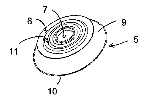
The cover according to the invention is shown in more detail in FIG. 2a-d.
FIG. 2a
illustrates the cover 5 in a perspective view, FIG. 2b in a top view, FIG. 2c
in a cross
sectional view along the line A-A as illustrated in FIG. 2b, and FIG. 2d shows
the cir-
cular cut of FIG. 2c in an enlarged view. The indicated dimensions in FIG. 2d
are only
exemplary and do not limit the invention in any way.
The cover 5 according to the invention comprises a flange 8 and a conical side
wall 9.
The flange 8 comprises an opening 7 through which flushing fluid is supplied.
The
cover 5 is produced in a flexible material such that its rim 10 adopts its
shape to the
surface 6 on which it is placed, for exainple a liinb of a patient.
The flange 8 has a corrugated part 11 which allows great mechanical
flexibility of the
rim of the opening 12 relative to the conical part 9. This is illustrated in
FIG. 4a and
4b. In FIG. 4a, the situation is shown, where a jet 14 of fluid, for example
water,
leaves the hand held unit 4 and flushes the central part 13 of the surface 6
inside the
CA 02656248 2008-12-10
WO 2006/131120 PCT/DK2006/000320
cover 5. In contrast to a solid shield or a semisolid shield without a high
flexibility, it
is possible with a cover according to the invention to tilt the hand piece 4
with respect
to the conical side wall 9 such that the jet 14' can be directed towards the
rim 10 of the
conical part 9 by which the complete area under the cover 5 can be flushed.
5
The parameters for the radii in the corrugated part and the other dimensions
as illus-
trated in FIG. 2d are for illustration only and not limiting for the invention
in any way.
FIG. 3 illustrates the mounting of the cover 5 on the hand piece 4. For
simplicity, the
cover is shown without corrugation. The hand piece 4 coinprises a shield in
the form
of a solid semi sphere 15 which tightly fits into the central opening 7 of the
flange 8 of
the cover 5. The edge 16 fits into a recess 17 as shown in the enlarged view
in FIG.
2d.
The hand piece 4 may optionally in addition have a regulator 18 for regulation
of the
amount of flushing fluid and for other parameters, for example pulsation
frequency,
the size of the jet 14 and flushing pressure.
The solid semi sphere 15 is preferably made of a transparent plastic. The semi
sphere
15 may alternatively be substituted by other connectors that fit into a
corresponding
opening 7. It is preferred that the material is transparent, and optionally,
it may include
a magnifying lens in order for the medical assistant to better see the
surface, for exam-
ple a wound on a limb of the patient. In certain circumstances, the flexible
cover 5,
though being fabricated in a transparent material, may not be as clearly
transparent as
the solid connector/semi sphere 15. Especially in this case, the lens in the
solid seini
sphere may be useful when the flushing is performed towards the rim 10 of the
cover 5
with a tilted hand piece 4 as illustrated in FIG. 4b, because the visual
distance through
the solid connector 15 to the rim 10 is longer and therefore, details are
harder to see
for the medical assistant. Thus, a built-in inagnifying lens gives a better
overview and
also makes it easier to see details for the assistant.
A suitable size for the flexible shied has proven to be between 130 mm and 170
mm.
The cover may be made of any elastic material, however, polyiner, especially
silicone,
has been observed as useful. The corrugated part has been tested for a
polyiner a thick-
CA 02656248 2008-12-10
WO 2006/131120 PCT/DK2006/000320
6
ness of 0.55 mm, wherein the amplitude for the corrugation was around 3 mm and
where the edge region of the flange 8 had a thickness of 1.6 mm. A useful
height is
between 1 and 5 cm, preferably around 3 cin.
Though the invention has been illustrated for medical usage, especially for
cleaning
peripheral organs, the cover according to the invention is of general nature
and may
find application also in other medical and non-medical fields.
The fluid to be provided by the hand held unit 4 would usually be a liquid but
the in-
vention is not limited to liquids such that a cover according to the invention
also may
be used in connection with high pressure gas stream, where the cover holds
debris
back to prevent spreading of it outside the cover.
An alternative embodiment of the invention is illustrated in FIG. 5a and 5b.
In this
embodiment, the hand-held unit is in the fonn of a syringe 4' with a tip 19 in
connec-
tion with a fluid reservoir 2' for providing fluid to the surface 6. The
syringe 4' is
connected to the cover 5 according to the invention via a connector in the
forin of a
small shield 15 or in the form of a sleeve 20 between the tip 19 and the cover
5. The
connector can be of other types as well.