Note : Les descriptions sont présentées dans la langue officielle dans laquelle elles ont été soumises.
CA 02657976 2013-12-10
66009-127
VEHICLE SURFACES CLEANING AND DE-ICING SYSTEM AND METHOD
REFERENCE TO RELATED APPLICATIONS
Reference is made to U.S. Provisional Patent Application Serial
No. 60/833,056, filed July 24, 2006 and entitled "Washer Fluid Heating
System",
U.S. Provisional Patent Application Serial No. 60/833,115, filed July 24, 2006
and entitled
"Washer Fluid Heating System" and U.S. Provisional Patent Application Serial
No. 60/836,734, filed August 7, 2006 and entitled "Liquid Heating System," the
priority of
which are hereby claimed.
Reference is made to PCT Application Serial No. PCT/IL2006/001209 filed
October 19, 2006.
Reference is made to U.S. Patent No. 7,445,165, issued November 4, 2008.
Reference is made to U.S. Patent No. 7,905,427, issued March 15, 2011.
Reference is made to U.S. Patent Nos. 6,164,564; 6,615,438; 6,669,109;
6,892,417; 7,108,754 and 7,171,716.
1
CA 02657976 2009-01-15
WO 2008/012801
PCT/1L2007/000910
FIELD OF THE INVENTION
The present invention relates generally to apparatus and methods for
heating liquid for use in cleaning or de-icing vehicle elements.
BACKGROUND OF THE INVENTION
The following publications are believed to represent the current state of
the art:
U.S. Patents: 653,629; 1,636,190; 2,607,944; 3,202,447; 3,203,447;
3,319,891; 3,332,045; 3,446,942; 3,427,675; 3,475,588; 3,632,042; 3,524,044;
3,537,900; 3,643,193; 3,711,679; 3,716,886; 3,747,500; 3,888,412; 3,977,436;
3,979,068; 4,090,668; 4,088,269; 4,106,508; 4,159,026; 4,212,425; 4,253,493;
4,295,111; 4,306,589; 4,403,765; 4,489,863; 4,508,957; 4,524,797; 4,534,539;
4,561,632; 4,574,841; 4,616,780; 4,638,525; 4,690,371; 4,815,662; 4,834,289;
4,877,186; 4,832,262; 4,922,570; 4,946,009; 4,999,550; 5,012,977; 5,034,714;
5,118,040; 5,134,266; 5,141,157; 5,141,160; 5,173,586; 5,203,049; 5,254,083;
5,271,120; 5,318,071; 5,345,968; 5,351,934; 5,354,965; 5,383,247; 5,423,486;
5,467,522; 5,509,606; 5,561,882; 5,636,407; 5,650,080; 5,673,360; 5,711,486;
5,711,487; 5,727,769; 5,762,278; 5,784,751; 5,823,439; 5,881,428; 5,903,953;
5,927,608; 5,944,910; 5,947,348; 5,957,384; 5,965,950; 5,979,796; 5,988,523;
5,988,529; 6,008,474; 6,024,803; 6,029,908; 6,032,324; 6,050,503; 6,082,632;
6,133,546; 6,164,564; 6,155,493; 6,199,587; 6,220,524; 6,223,951; 6,236,019;
6,257,500; 6,281,649; 6,286,174; 6,330,497; 6,781,056; 6,841,739; 6,896,199;
6,615,438; 6,669,109; 6,892,417; 7,108,754 and 7,171,716.
Published PCT Applications: WO 2007/046106, WO 2005/076735, WO
2004/035358, WO 02/092237, WO 00/27540 and WO 98/58826.
2
CA 02657976 2009-01-15
WO 2008/012801
PCT/1L2007/000910
SUMMARY OF THE INVENTION
The present invention seeks to provide improved apparatus and methods
for heating liquid for use in cleaning or de-icing vehicle surfaces.
There is thus provided in accordance with a preferred embodiment of the
present invention a liquid heating unit for use in a vehicle surface cleaning
and deicing
system, the liquid heating unit including a liquid heating assembly, having an
inlet
through which a washing fluid is received from a reservoir and an outlet
through which
the fluid is discharged for cleaning at least one vehicle surface, at least
one heating
element for heating fluid in the liquid heating assembly and a freeze
protection element
located in the liquid heating assembly, the freeze protection element
including a
deformable container being deformable in at least two generally perpendicular
axial
directions.
Preferably, the container defines an interior volume and the container is
inwardly deformable into the interior volume. Additionally or alternatively,
the
container includes a generally cylindrical container. Additionally or
alternatively the
freeze protection element also includes a sealing element.
Preferably, the freeze protection element is formed of a flexible material.
Additionally or alternatively, the freeze protection element is formed of a
resilient
material.
Preferably, the freeze protection element is operative to generally prevent
fluid from passing therethrough. Additionally or alternatively, the container
is
deformable in three generally perpendicular axial directions.
There is also provided in accordance with another preferred embodiment
of the present invention a vehicle surface cleaning and deicing system
including at least
one vehicle surface sprayer, a reservoir, a liquid heating assembly, having an
inlet
through which a washing fluid is received from the reservoir and an outlet
through
which the fluid is supplied to the at least one :vehicle surface sprayer for
spraying onto
at least one vehicle surface, at least one heating element for heating fluid
in the liquid
heating assembly and a manifold in fluid communication with the at least one
vehicle
surface sprayer, the reservoir and the liquid heating assembly, the manifold
including an
3
CA 02657976 2009-01-15
WO 2008/012801
PCT/1L2007/000910
=
input conduit along a first fluid flow path connecting the reservoir and the
liquid heating
assembly, an output conduit along a second fluid flow path connecting the
liquid
heating assembly and the at least one vehicle surface sprayer, a connecting
conduit
connecting the input conduit and the output conduit, a first one-way valve
located along
the first flow path operative to allow fluid flow from the reservoir to the
liquid heating
assembly and a second one-way valve located along the connecting conduit
operative to
permit flow from the output conduit to the input conduit.
Preferably, the manifold also includes an additional connecting conduit
connecting the input conduit and the output conduit and a third one-way valve
located
along the additional connecting conduit operative to permit flow from the
input conduit
to the output conduit. Alternatively or additionally, the first one-way valve
is a pressure
operated one-way valve. Additionally or alternatively, the second one-way
valve is a
pressure operated one-way valve. Additionally or alternatively, the vehicle
surface
cleaning and deicing system also includes at least one additional one-way
valve located
along the second fluid flow path upstream of the manifold and downstream of
the at
least one vehicle surface sprayer.
Preferably, the manifold is suitable for use both in vehicles that include at
least one additional one-way valve, located along the second fluid flow path
upstream of
the manifold and downstream of the at least one vehicle surface sprayer, and
vehicles
that do not include the at least one additional one-way valve.
There is yet further provided in accordance with still another preferred
embodiment of the present invention a liquid' heater including a housing
defining an
liquid inlet and a liquid outlet and at least one heating element disposed in
the housing,
the housing and the at least one heating element defining at least one liquid
flow path
between the inlet and the outlet, the at least one heating element operative
to heat liquid
flowing through the housing along the at least one liquid flow path, the at
least one
heating element including a circuit board substrate, at least one electrical
circuit formed
on the circuit board substrate and at least one heating trace formed over at
least a
portion of the at least one electrical circuit.
Preferably, the at least one heating trace and the at least one electrical
. . circuit are formed of the same material. Alternatively, the at least
one heating trace and
4
=
CA 02657976 2009-01-15
WO 2008/012801
PCT/1L2007/000910
the at least one electrical circuit are formed of different materials.
Additionally or
alternatively, the at least one heating trace is formed of a composite
material.
Preferably, the at least one heating trace includes at least one serpentine
heating trace.
There is even further provided in accordance with yet another preferred
embodiment of the present invention a method for supplying liquid for use in
cleaning
at least one of a plurality of vehicle surfaces, the method including
receiving at least one
input relating to at least one vehicle operating parameter selected from the
group
consisting of a gear selection, an engine on/off indication, an engine speed
above or
below idling speed indication, a vehicle speed and direction of vehicle
movement
indicator, an engine torque and an engine power level, selecting at least one
vehicle
surface of the plurality of vehicle surfaces based at least partially on the
at least one
input relating to the at least one vehicle operating parameter and discharging
the liquid
through an outlet onto the at least one vehicle surface selected.
Preferably, the selecting at least one vehicle surface includes selecting
multiple vehicle surfaces and selecting a sequential order for discharging the
liquid onto
the multiple vehicle surfaces and the discharging includes discharging the
liquid onto
the multiple vehicle surfaces in the sequential order. Additionally, the
discharging the
liquid onto the multiple vehicle surfaces in the sequential order includes
initiating at
least one discharge in the sequential order prior to the completion of the
previous
discharge in the sequential order.
Alternatively, the selecting at least one vehicle surface includes selecting
multiple vehicle surfaces and the discharging includes discharging the liquid
onto the
multiple vehicle surfaces at least partially simultaneously. Alternatively,
the method
also includes at least one additional iteration of the receiving, the
selecting and the
discharging.
Preferably, the method also includes heating the liquid prior to the
discharging. Additionally or alternatively, the method also includes selecting
a liquid
source for the liquid prior to the discharging.
Preferably, the selecting also includes receiving at least one sensor input
from at least one sensor and selecting the at least one vehicle surface based
at least
partially on the at least one sensor input. Additionally, the at least one
sensor includes at
5
=
CA 02657976 2012-09-12
66009-127
least one sensor selected from the group consisting of a dirt sensor, a
temperature
sensor, a liquid level sensor, a wind speed sensor and a rain sensor.
There is also provided in accordance with yet another preferred
embodiment of the present invention a system for supplying liquid for use in
cleaning at
least one of a plurality of vehicle surfaces, the system including a liquid
reservoir, at
least one liquid outlet in fluid communication with the liquid reservoir, a
pump, and a
controller operative to receive at least one input relating to at least one
vehicle operating
parameter, to select at least one vehicle surface of the plurality of vehicle
surfaces based
at least partially on the at least one input relating to at least one vehicle
operating
parameter and to provide an input to the pump to provide a discharge of the
liquid
through the liquid outlet onto the at least one vehicle surface selected, the
at least one
vehicle operating parameter being selected from the group consisting of a gear
selection, an engine on/off indication, an engine speed above or below idling
speed
indication, a vehicle speed and direction of vehicle movement indicator, an
engine
torque and an engine power level.
There is further provided in accordance with still another preferred
embodiment of the present invention a method for supplying liquid for use in
cleaning
multiple vehicle surfaces of a plurality of vehicle surfaces, the method
comprising
receiving at least one input relating to at least one vehicle operating
parameter, selecting
said multiple vehicle surfaces based at least partially on said at least one
input relating
to said at least one vehicle operating parameter and selecting a sequential
order for
discharging said liquid onto said multiple vehicle surfaces and discharging
said liquid
through an outlet onto said multiple vehicle surfaces in said sequential
order.
6
CA 02657976 2012-09-12
=
66009-127
There is still further provided in accordance with yet another embodiment of
the present invention a liquid heater comprising: a housing having a
continuous, substantially
vertical side wall, said side wall defining an area therein and having a
liquid inlet and a liquid
outlet therein; a first heat dissipation element, having opposing inner and
outer surfaces,
disposed against a first edge of said housing side wall and orthogonal
thereto, said first heat
dissipation element having heat transfer projections extending from said inner
surface into
said area defined by said side wall, said housing and said first heat
dissipation element at least
partially defining a liquid flow path between said inlet and said outlet; and
a first heating
element disposed proximate said outer surface of said first heat dissipation
element, said first
heating element operative to heat said first heat dissipation element and
thereby liquid flowing
within said housing along said liquid flow path, said first heating element
comprising a circuit
board substrate, at least one electrical circuit formed on said circuit board
substrate, and at
least one heating trace formed over at least a portion of said at least one
electrical circuit.
6a
CA 02657976 2009-01-15
WO 2008/012801
PCT/1L2007/000910
BRIEF DESCRIPTION OF THE DRAWINGS
The present invention will be understood and appreciated more fully
from the following detailed description, taken in conjunction with the
drawings in
which:
Fig. 1 A is a simplified pictorial illustration of a vehicle surface cleaning
and de-icing system, constructed and operative in accordance with a preferred
embodiment of the present invention, installed in a vehicle;
Fig. 1B is a simplified exploded view pictorial illustration of the liquid
heating unit forming part of the vehicle surface cleaning and de-icing system
of Fig. 1A;
Figs. 2A and 2B are simplified sectional illustrations of the liquid heating
unit of Figs. 1A and 1B, taken along lines HA-IIA and TTB-1113 of Fig. 1A,
respectively;
Fig. 3 is a simplified pictorial illustration of a freeze protection element
for use in the liquid heating unit of Figs. 1A-2B;
Figs. 4A and 4B are simplified sectional illustrations of the freeze
protection element of Fig. 3, taken, along lines WA-WA and IVB-IVB of Fig. 3,
respectively;
Fig. 5 is a simplified pictorial illustration of a freeze protection element
of Fig. 3 in a deformed state;
Figs. 6A and 6B are simplified sectional illustrations of the freeze
protection element of Fig. 5, taken along lines VIA-VIA and VIB-VIB of Fig. 5,
respectively;
Fig. 7 is a simplified exploded view pictorial illustration of the manifold
of Figs. 1A-2B;
= Figs. 8A and 8B are simplified sectional illustrations of the manifold of
Figs. 1A-2B and 7, taken along lines VIII-VIII of Fig. 1B;
= Fig. 9 is a simplified sectional illustration of a manifold for use with
the
liquid heating unit of Figs. 1A-2B, in accordance with another preferred
embodiment of
the present invention;
7
=
CA 02657976 2009-01-15
WO 2008/012801
PCT/1L2007/000910
Fig. 10A is a simplified pictorial illustration of a liquid heater for use in
the system of Figs. 1A-2B, in accordance with another preferred embodiment of
the
present invention;
Fig. 10B is a simplified exploded view pictorial illustration of the liquid
heater of Fig. 10A;
Fig. 11 is a simplified sectional illustration of the liquid heater of Figs.
10A and 10B, taken along lines XI-XI of Fig. 10A;
Fig. 12 is a simplified sectional illustration of a liquid heater, similar to
the liquid heater of Figs. 10A-11, constructed and operative in accordance
with another
embodiment of the present invention;
Fig. 13 is a simplified sectional illustration of another liquid heater,
constructed and operative in accordance with another embodiment of the present
invention;
Fig. 14 is a simplified schematic illustration of a system for heating
liquid for use by a vehicle fuel cell, constructed and operative in accordance
with
another preferred embodiment of the present invention;
Figs. 15A and 15B are simplified schematic illustrations of a vehicle
surface cleaning and de-icing system including vehicle surface selection
functionality,
constructed and operative in accordance with another preferred embodiment of
the
present invention; and
Fig. 16 is a simplified flow chart of a preferred mode of operation of a
vehicle surface cleaning and de-icing system of Figs. 15A and 15B.
=
8
=
CA 02657976 2009-01-15
WO 2008/012801
PCT/1L2007/000910
DETAILED DESCRIPTION OF PREFERRED EMBODIMENTS
It is appreciated that the term "vehicle" as used in the context of the
present patent application and in the claims can refer to any type of wheeled
vehicle
having windows or any other interior or exterior surface requiring cleaning
and/or de-
icing, such as an automobile or a truck, as well as a boat or an airplane.
It is also appreciated that, even though the present invention is shown in
the context of a windshield cleaning and de-icing system, the systems and
methods of
the present invention can be utilized to clean and/or de-ice any interior or
exterior
vehicle surface including, for example, front and/or rear windshields,
mirrors, windows,
headlights, tail lights, radar, radome. It is further appreciated that the
cleaning and de-
icing system of the present invention may also be used to clean and/or de-ice
any
vehicle surface that transmits or receives energy, such as, but not limited
to, visible
light, infrared light, RF energy and UV energy.
It is appreciated that the terms "cleaning" and "de-icing" as used in the
context of the present patent application and in the claims are used
interchangeably to
refer to apparatus, systems and methods for removing ice, snow and/or any
other
foreign matter from vehicle interior or exterior surfaces requiring cleaning
and/or de-
icing.
It is appreciated that the terms "non heat conductive material" and "heat
conductive material" as used in the context of the present patent application
and in the
claims, refers to materials which are known in the art to be relatively poor
heat
conductors and relatively good heat conductors, respectively. It is
appreciated that the
terms "non electrically conductive material" and "electrically conductive
material" as
used in the context of the present patent application and in the claims,
refers to materials
which are known in the art to be relatively poor conductors of electricity and
relatively
good conductors of electricity, respectively.
It is appreciated that the term "controller", as used in context of the
present patent application and in the claims, may refer to a controller which
forms part
of the vehicle surface cleaning and de-icing system of the present invention,
or to a
vehicle computer or computers or to any combination thereof. The controller
may be in
9
=
CA 02657976 2009-01-15
WO 2008/012801
PCT/1L2007/000910
communication with a vehicle computer or computers and one or more sensors, as
described further hereinbelow.
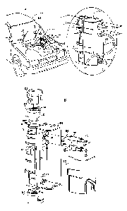
Reference is now made to Fig. 1A, which is a simplified pictorial
illustration of a vehicle surface cleaning and de-icing system, constructed
and operative
in accordance with a preferred embodiment of the present invention, installed
in a
vehicle, Fig. 1B, which is a simplified exploded view pictorial illustration
of a liquid
heating unit forming part of the vehicle surface cleaning and de-icing system
of Fig. 1A,
and to Figs. 2A and 2B, which are simplified sectional illustrations of the
liquid heating
unit of Figs. lA and 1B.
As seen in Fig. 1A, an otherwise conventional vehicle 100 is seen to
incorporate a vehicle surface cleaning and de-icing system 120 for cleaning
and/or de-
icing a vehicle surface, such as a windshield 124. The vehicle surface
cleaning and de-
icing system 120 preferably includes a liquid heating unit 126, including a
liquid
heating assembly 128, for heating liquid received from a reservoir 130, which
provides
heated liquid, such as water or windshield cleaning liquid, to at least one
sprayer 132 for
spraying onto windshield 124. Liquid heating unit 126 has an inlet 134, which
receives
liquid from reservoir 130, and an outlet 136 through which heated liquid is
discharged
to at least one sprayer 132. The liquid is driven by a pump 140, which is
generally
already present in vehicle 100 for spraying unheated liquid to clean
windshield 124.
A battery 142 provides power to vehicle surface cleaning and de-icing
system 120, and wipers 144 clean melted ice and dirt from the windshield 124,
as is
known in the art. A controller 146 regulates the operation of vehicle surface
cleaning
and de-icing system 120, and optionally also controls wipers 144 in
conjunction with
operation of vehicle surface cleaning and de-icing system 120.
One or more temperature sensors, in communication with controller 146,
are preferably provided to measure the temperature of the liquid in liquid
heating
assembly 128 and may also measure the temperature of the at least one sprayer
132.
Additionally, one or more temperature sensors, preferably in communication
with
controller 146, may be provided to measure the temperature external to liquid
heating
assembly 128, such as a windshield temperature sensor (not shown), a vehicle
exterior
temperature sensor (not shown) and a vehicle interior temperature sensor (not
shown).
=
CA 02657976 2013-12-10
66009-127
=
It is appreciated that at least one sprayer 132, which is located on a wiper
arm in the illustiated embodiment, may be located in any other suitable
location, such as
adjacent windshield 124 or on wipers 144.
Additional sensors may also be provided, such as a wind speed sensor or
a dirt sensor. Controller 146 may also be operative to receive additional
inputs
concerning vehicle operational parameters and/or external conditions from a
vehicle
= computer and/or from existing vehicle sensors.
As seen further in Figs. 1B, 2A and 2B, liquid heating unit 126 comprises
a housing 150 including a main housing portion 154, a removable cover housing
portion
156, a first cap portion 158 and a second cap portion 160.
Main housing portion 154 preferably defines a first manifold engagement
Surface 170 defining a liquid inlet aperture 174 and a Second monifold
engagement
surface 176 defining a liquid outlet aperture 178.
Main housing portion 154 also preferably defines an interior volume in
vyhich is disposed liquid heating =assembly 128. At. least one heating element
182 is
disposed within liquid heating assembly 128 for heating liquid therein. As
seen
particularly in Fig. 2B, liquid inlet aperture 174 and liquid outlet aperture
178 are both
in fluid communication with liquid heating assembly 128 and a monifold 200.
It is appreciated that liquid heating assembly 128 may be any liquid heating
assembly suitable for use in a vehicle, including but not limited to those
described in
U.S. Patent Nos. 6,164,564; 6,615,438; 6,669,109; 6,892,417; 7,108,754;
7,171,716;
7,445,165; and 7,905,427, and PCT Application Serial No. PCT/EL2006/001209.
Manifold 200 is preferably configured, at one end thereof, to engage first
.msnifold engagement surface 170 and second rnAnifold engagement surface 176
via
connectors 202 and 204, respectively. At an opposite end of manifold 200 are
provided
an inflow connector 206, for connecting to inlet 134, providing liquid from
reservoir
130, and an outflow connector 208, for connecting to an outlet 136 providing
liquid to
at least one -sprayer 132. Liquid is preferably supplied to liquid heating
assembly 128
from reservoir 130 via inlet 134, manifold 200 and liquid inlet aperture 174.
Liquid is
11
=
=
CA 02657976 2009-01-15
WO 2008/012801
PCT/1L2007/000910
preferably provided from liquid heating assembly 128 to at least one sprayer
132 via
liquid outlet aperture 178, manifold 200 and outlet 136.
Liquid heating unit 126 also preferably includes a freeze protection
element 250 to prevent damage to housing 150 and liquid heating assembly 128
in the
event of freezing of liquid within liquid heating unit 126. Freeze protection
element 250
is preferably formed of a flexible, resilient material, such as silicon or
rubber. In the
event of expansion of the liquid in liquid heating assembly 128 due to
freezing, freeze
protection 'element 250 is operative to defoini inwardly, as described further
hereinbelow in reference to Figs. 5-6B, and thereby prevent damage to liquid
heating
unit 126.
Freeze protection element 250 preferably comprises a generally
cylindrical container portion 252 defining an interior volume 254. Freeze
protection
element 250 also preferably includes a generally annular sealing element 256
configured to engage an upper surface 260 of main housing portion 154.
As seen in Figs. 2A and 2B, freeze protection element 250 is preferably
inserted into a volume 270 defined in main housing portion 154 above liquid
heating
assembly 128. Freeze protection element 250 is preferably in sealing
engagement with
an interior surface 275 of main housing portion 154 to prevent liquid passage
from
liquid heating assembly 128 into interior volume 254. First cap portion 158
preferably
engages main housing portion 154 and is operative to prevent sealing element
256 from
disengaging with upper surface 260 of main housing portion 154.
Reference is now made to Fig. 3, which is a simplified pictorial
illustration, and to Figs. 4A and 4B, which are simplified sectional
illustrations, of a
preferred embodiment of freeze protection element 250 of Figs. 1A-2B.
As seen in Figs. 3, 4A and 4B, freeze protection element 250 preferably
comprises an integrally formed, generally cylindrical wall portion 280, a
generally
circular bottom portion 282 and generally annular sealing element 256. Freeze
protection element 250 is preferably formed of a flexible, resilient material
and is
configured to be inwardly deform.able when pressure is applied to circular
floor portion
282 from below.
As seen particularly in Figs. 4A-4B, annular sealing element 256 is
preferably formed with an overhang 284 configured to engage upper surface 260
of
12
CA 02657976 2009-01-15
WO 2008/012801
PCT/1L2007/000910
main housing portion 154. Sealing element 256 is operative to generally
maintain freeze
protection element 250 in proper orientation within volume 270.
Reference is now made to Fig. 5, which is a simplified pictorial
illustration, and to Figs. 6A and 6B, which are simplified sectional
illustrations, of the
freeze protection element 250 of Figs. 1A-4B in a deformed state.
As seen in Fig. 5, when pressure is applied to an outer surface of
generally circular bottom portion 282 of freeze protection element 250 from
outside
freeze protection element 250, such as may be caused by freezing of liquid in
liquid
heating assembly 128, as indicated by arrow 290, freeze protection element 250
is
operative to deform inwardly into interior volume 254. Freeze protection
element 250 is
preferably operative to deform inwardly in at least two perpendicular axial
directions,
and may be defoimable is all three axial directions.
As seen further in Figs. 6A and 6B, cylindrical wall portion 280 of freeze
protection element 250 may deform inwardly along both an X axis, as seen in
Fig. 6A,
and along a Y axis, as seen in Fig 6B. Circular bottom portion 282 may also
defoiin
inwardly along a Z axis. It is appreciated that the flexible and resilient
properties of
freeze protection element 250 enable freeze protection element 250 to
simultaneously
defoun along multiple axes. It is also appreciated that the provision of
interior volume
254 of freeze protection element 250 enables freeze protection element 250 to
deform
inwardly generally without any outward deformation.
Reference is now made to Fig. 7, which is a simplified exploded view =
pictorial illustration of manifold 200 of Figs. 1A-2B, and to Figs. 8A and 8B,
which are
simplified sectional illustrations of manifold 200 in two different sprayer
configurations.
As seen in Figs. 7, 8A and 8B, manifold 200 preferably includes an input
conduit 300, forming part of a first fluid flow path from reservoir 130 to
liquid heating
assembly 128, as indicated by arrows 305, and an output conduit 310, forming
part of a
second fluid flow path from liquid heating assembly 128 to at least one
sprayer 132, as
indicated by arrows 315. Input conduit 300 is preferably connected at inflow
connector
206 to inlet 134 (Fig. 1A) and output conduit 310 is preferably connected at
outflow
connector 208 to outlet 136. Manifold 200 also includes a connecting conduit
320
connecting input conduit 300 and output conduit 310.
=
13
CA 02657976 2009-01-15
WO 2008/012801
PCT/1L2007/000910
Input conduit 300 includes a first one-way valve 330 and connecting
conduit 320 includes a second one-way valve 340. First one-way valve 330 is a
normally closed valve, which prevents fluid flow from liquid heating assembly
128 to
reservoir 130, and is opened when pump 140 (Fig. 1A) is operative to provide
liquid
under pressure from reservoir 130 to liquid heating assembly 128. Second one-
way
valve 340 is a normally open valve, when pump 140 is closed, which allows
fluid to
flow from output conduit 310 to input conduit 300, and is closed when pump 140
is
operative to provide liquid under pressure from reservoir 130 to liquid
heating assembly
128.
Fig. 8A illustrates the fluid flows provided by manifold 200 when used
with a vehicle surface cleaning and de-icing system 120 including at least one
additional
one-way valve 350, along the second fluid flow path from liquid heating
assembly 128
to sprayers 132, upstream of manifold 200 and downstream of sprayers 132.
Additional
one-way valve 350 is a normally closed valve, when pump 140 is closed, which
is
opened by pressure from liquid flowing to sprayers 132 from liquid heating
assembly
128 when pump 140 is operative. Additional one-way valve 350 is generally
provided
in a vehicle to allow liquid to remain in outlet 136 when pump 140 is closed
and thereby
provides a shorter time interval, between the actuation of pump 140 and
provision of
liquid to sprayers 132, than when additional one-way valve 350 is not
provided, as
described hereinbelow with reference to Fig. 8B. The combination of second one-
way
valve 340 and additional one-way valve 350 is also operative to prevent liquid
in outlet
136 from exiting through sprayers 132 when pump 140 is closed.
In this vehicle configuration, manifold 200 is operative to provide the
following fluid flows during operation of liquid heating unit 126. When pump
140 is
operative, in response to an input from controller 146, to provide liquid to
liquid heating
assembly 128, liquid under pressure is provided through inlet 134 to input
conduit 300.
The liquid is operative to open first one-way valve 330 to allow liquid to
flow in the
direction of arrows 305, and to close second one-way valve 340 so that liquid
from
liquid heating assembly 128 flows through output conduit 310, in the direction
of
= 30 arrows 315, through outlet 136 and additional one-way valve 350 to
sprayers 132.
When pump 140 is closed, in response to an input from controller 146,
first one-way valve 330 closes and prevents liquid flow from liquid heating
assembly
14
=
CA 02657976 2009-01-15
WO 2008/012801
PCT/1L2007/000910
128 to reservoir 130. When pump 140 is closed, second one-way valve 340 is
open so
that excess liquid and vapor, located upstream of first one-way valve 330 and
downstream of additional one-way valve 350, including liquid and vapor in
liquid
heating assembly 128, output conduit 310, or outlet 136, will flow through
connecting
= 5
conduit 320, in the direction of arrows 360, through input conduit 300 to
reservoir 130.
The provision of second one-way valve 340 prevents this excess liquid and
vapor from
dripping through sprayers 132 onto windshield 124, or other vehicle surfaces
located
adjacent sprayers 132.
It is appreciated that in the event that at least one sprayer 132 includes
multiple sprayers 132, each of multiple sprayers 132 must be located upstream
of at
least one additional valve 350.
Fig. 8B illustrates the fluid flows provided by manifold 200 when used
with a vehicle surface cleaning and de-icing system 120 not including
additional one-
way valve 350 of Fig. 8A along the second fluid flow path from liquid heating
assembly
128 to sprayers 132 upstream of manifold 200 and downstream of sprayers 132.
In this vehicle configuration, manifold 200 is operative to provide the
following fluid flows during operation of liquid heating unit 126. When pump
140 is
operative, in response to an input from controller 146, to provide liquid to
liquid heating
assembly 128, liquid under pressure is provided through inlet 134 to input
conduit 300.
The liquid is operative to open first one-way valve 330 to allow liquid to
flow in the
direction of arrows 305, and to close second one-way valve 340 so that liquid
from
liquid heating assembly 128 flows through output conduit 310, in the direction
of
arrows 315, through outlet 136 to sprayers 132. .
When pump 140 is closed, in response to an input from controller 146,
first one-way valve 330 closes and prevents liquid flow from liquid heating
assembly
128 to reservoir 130. When pump 140 is closed, second one-way valve 340 opens
so
that excess liquid remaining upstream of valve 340, including liquid in outlet
136 and
output conduit 310, will flow through connecting conduit 320, in the direction
of arrows
360, through input conduit 300 to reservoir 130.
In the vehicle configuration of Fig. 8B, second one-way valve 340 in
manifold 200 thus provides for the draining of fluid remaining in the fluid
flow path
=
CA 02657976 2009-01-15
WO 2008/012801
PCT/1L2007/000910
upstream of second one-way valve 340 to reservoir 130 upon the conclusion of
spraying.
The absence of additional one-way valve 350 permits liquid to drain
when pump 140 is closed. This configuration requires a longer time interval,
than the
time interval required when additional one-way valve 350 is provided, between
the
actuation of pump 140 and provision of liquid to sprayers 132.
It is appreciated that the manifold 200 thus provides multiple fluid flow
paths and is suitable for use both in vehicles that include additional one-way
valve 350
and vehicles that do not include additional one-way valve 350.
Reference is now made to Fig. 9, which is a simplified sectional
illustration of a manifold for use with the liquid heating unit of Figs. 1-2B,
in
accordance with another preferred embodiment of the present invention.
As seen in Fig. 9, a manifold 400 preferably includes an input conduit
402, forming part of a first fluid flow path from reservoir 130 to liquid
heating assembly
128, as indicated by arrows 405, and an output conduit 410, forming part of a
second
fluid flow path from liquid heating assembly 128 to sprayers 132, as indicated
by
- arrows 415. Input conduit 402 is preferably connected at inflow connector
416 to inlet
134 (Fig. IA) and output conduit 410 is preferably connected at outflow
connector 418
to outlet 136 (Fig. 1A). Manifold 400 also includes a first connecting conduit
420 and a
second connecting conduit 422 connecting input conduit 402 and output conduit
410.
Input conduit 402 includes a first one-way valve 430, first connecting
conduit 420 includes a second one-way valve 440 and second connecting conduit
422
includes a bypass valve 450. First one-way valve 430 is a normally closed
valve, which
prevents fluid flow from liquid heating assembly 128 to reservoir 130 and is
opened
when pump 140 (Fig. 1A) is operative to provide liquid under pressure from
reservoir
130 to liquid heating assembly 128. Second one-way valve 440 is a normally
open
valve, when pump 140 is closed, which allows fluid to flow from output conduit
410 to
input conduit 402 and is closed when pump 140 is operative to provide liquid
under
pressure from reservoir 130 to liquid heating assembly, 128. Bypass valve 450
is a
spring loaded one-way valve which permits liquid to bypass liquid heating
assembly
128 and flow directly from input conduit 402 through output conduit 410 and
outlet 136
to sprayers 132, when the pressure differential thereacross reaches a
predetermined
16
CA 02657976 2009-01-15
WO 2008/012801
PCT/1L2007/000910
threshold, typically 0.3 - 0.5 bar, which indicates the existence of a
blockage in the fluid
flow path through valve 430 and the liquid heating assembly 128.
Manifold 400 provides fluid flows similar to the fluid flows provided by
manifold 200, as described hereinabove with reference to Figs. 8A and 8B.
Manifold
400 is thus also suitable for use both in vehicles that include additional one-
way valve
350, as described hereinabove with reference to Fig. SA, and vehicles that do
not
include additional one-way valve 350, as described hereinabove with reference
to Fig.
8B.
Reference is now made to Figs. 10A, 10B and 11, which are,
respectively, a simplified assembled pictorial illustration, a simplified
exploded view
pictorial illustration and a simplified sectional illustration of a liquid
heater for use in
the system of Figs. 1A-2B.
As seen in Figs. 10A, 10B and 11, a liquid heater 600 comprises a
housing element 610 including an inlet 612 and an outlet 614. Housing element
610 is
preferably formed of plastic, but may also be .made of any suitable material,
such as
aluminum. Disposed within housing element 610 is at least one heat dissipation
element
616, preferably a pair of heat dissipation elements 616, having formed, on an
inward
facing surface 618 thereof, protruding elements, such as ridges or protrusions
620.
Ridges or protrusions 620 of heat dissipation element 616 define at least one
liquid flow
path, such as flow channels 622, preferably providing a large contact surface
area for
rn
maximizing heat transfer to a liquid flowing therethrough. Flow channels 622
are
preferably in fluid communication with inlet 612 and outlet 614.
An outward facing surface of heat dissipation element 616 preferably
engages an electronically insulative, thermal conductive pad 626. An outward
facing
surface of thermal conductive pad 626 preferably engages a heating element
630.
Electronically insulative, thermal conductive pad 626 is preferably formed of
a non-
electrically conductive, heat conductive material and provides electrical
insulation
between the heat dissipation element 616 and heating element 630 while
providing good
thermal conductivity.
Heating element 630 preferably comprises a substrate, such as a printed
= circuit board (PCB) .634, including at least one electrical circuit
having formed on at
least a portion thereof at least one heating trace 640, which preferably
comprises
17
CA 02657976 2009-01-15
WO 2008/012801
PCT/1L2007/000910
copper, nickel or nickel-chrome. It is appreciated that heating trace 640 may
comprise a
different material than the material of the electrical circuit upon which it
is formed or
may comprise the same material as the electrical circuit upon which it is
formed.
Heating trace 640 is preferably arranged in a generally serpentine
arrangement to maximize the surface area of PCB 634 covered thereby and to
maximize
the heat provision therefrom. In a preferred embodiment, heating element 630
includes
two heating traces 640, each arranged in a generally serpentine arrangement.
PCB 634
may have mounted thereon sensors and other control circuitry elements, as
described
hereinbelow with reference to Fig. 12.
It is appreciated that heating trace 640 is preferably formed of a material,
such as copper, nickel or nickel-chrome, having increased resistance as it is
heated, thus
generating less current, less power and less heat energy as the temperature
increases. It
is appreciated that by measuring the current through heating trace 640 and the
voltage
thereon, the resistance thereof may be calculated and correlated to the
temperature
thereof. This temperature generally provides an average temperature along
heating trace
640, rather than a single location temperature that would be provided by a
temperature
sensor, and is preferably provided as an input for use in controlling heating
element
630.
Liquid heater 600 may also include a power disconnect, such as a thermal
fuse (not shown), as a protection mechanism against overheating. As described
further
hereinbelow, liquid heater 600 may also include at least one sensor and/or
control
circuitry integrated with PCB 634 to provide low cost, robust design and ease
of
assembly thereof.
An outward facing surface of heating element 630 preferably engages a
thermal insulative pad 644. An outward facing surface of thermal insulative
pad 644
preferably engages a pressure plate 650. Pressure plate 650 preferably is
operative to
ensure that heating element 630 is generally evenly pressed against heat
dissipation
element 616.
Liquid heater 600 also preferably includes a sealing frame 660 between
dissipation element 616 and housing element 610. Preferably, housing element
610,
.
dissipation element 616, pad 644, sealing frame 660 and pressure plate 650 are
provided
with a plurality of apertures 670 therearound, operative to accommodate screws
or other
18
CA 02657976 2009-01-15
WO 2008/012801
PCT/1L2007/000910
connecting elements. Pressure plate 650 is preferably connected to housing
element 610
by connecting elements such as screws, which preferably extend through
apertures 670
in pressure plate 650, pad 644, dissipation element 616 and sealing frame 660
into
apertures 670 in housing element 610.
A liquid preferably enters the system through inlet 612, and flows
through flow channels 622 in thermal contact with ridges or protrusions 620 of
heat
dissipation elements 616 and is heated thereby. It is appreciated that the
provision of
electronically insulative, thermal conductive pads 626 provide electrical
insulation
between heat dissipation elements 616 and heating elements 630 while providing
thermal conductivity to provide efficient heat transfer to liquid flowing
through flow
channels 622.
As described hereinabove, liquid heater 600 is particularly suitable for
heating of liquids used in a vehicle, such as a fluid for cleaning or de-icing
a vehicle
surface. As described further hereinbelow, liquid heater 600 is also suitable
for heating
liquid fuel cell coolant, where the temperature of the fuel cell coolant must
be
maintained at a temperature greater than a minimum threshold temperature in
order for
the fuel cell to function properly.
It is appreciated that liquid heater 600 is suitable for heating high liquid
flows, typically from 5 ¨ 160 liters per minute (1pm). Liquid heater 600
preferably
includes two operating modes, an idle mode, during which heating elements 630
are not
energized and do not generate heat, and an operational mode, where heating
elements
630 are energized and generate heat. Liquid heater 600 thus operates with
little or no
thermal hysteresis, since heat is generated only when heating elements 630 are
energized and heat is not generated when power is removed from heating
elements 630.
It is appreciated that the operational mode of liquid heater 600 may also
include setting a power level for the operation of heating elements 630. The
power level =
may be based on sensing a temperature of the liquid at any suitable point
along the flow
thereof, such as within liquid heater 600 or upstream or downstream therefrom,
and
comparing the liquid temperature to a threshold temperature, or any other
suitable
= method. Liquid heater 600 may include at least one temperature sensor to
monitor the
temperature of the liquid to prevent overheating of the liquid. Additionally,
liquid heater
600 may also include at least one temperature sensor to monitor the
temperature of
19
CA 02657976 2009-01-15
WO 2008/012801
PCT/1L2007/000910
liquid heater 600 and to prevent excessive heating thereof. Additional
temperature
sensors may also be provided, such as a temperature sensor to measure a
temperature
within a vehicle external to -liquid heater 600 or a temperature external to
the vehicle.
Liquid heater 600 is also designed to minimize pressure drop at all flow
rates. Heat dissipation elements 616 include a large surface area to maximize
contact
with the fluid and a flow channel designed to maximize the transfer of heat to
the fluid.
Liquid heater 600 also preferably includes electrical connectors 676 and
678, and temperature sensor connector 680. An inlet connector 682 is attached
to liquid
heater 600 at inlet 612 is and an outlet connector 684 is attached to liquid
heater 600 at
113 outlet 614.
Reference is now made to Fig. 12, which is a simplified sectional
illustration of a liquid heater, similar to the liquid heater of Figs. 10A-11.
As seen in
Fig. 12, a liquid heater 700 comprises a housing element 710 including an
inlet 712 and
an outlet 714. Housing element 710 is preferably formed of plastic, but may
also be
made Of any suitable material, such as aluminum. Disposed within housing
element 710
is at least one heat dissipation element 716, preferably a pair of heat
dissipation
elements 716, having formed, on an inward facing surface thereof, protruding
elements,
such as ridges or protrusions. Ridges or protrusions of heat dissipation
element 716
preferably define flow channels 722 providing a large contact surface area for
maximizing heat transfer to a liquid flowing therethrough. Flow channels 722
are
, preferably in fluid communication with inlet 712 and outlet 714.
An outward facing surface of heat dissipation element 716 preferably
engages an electronically insulative, thermal conductive pad 726. An outward
facing
surface of thermal conductive pad 726 preferably engages a heating element
730.
Electronically insulative, thermal conductive pad 726 is preferably formed of
a non-
electrically conductive, heat conductive material and provides electrical
insulation
between the heat dissipation element 716 and heating element 730 while
providing good
thermal conductivity.
Heating element 730 preferably comprises a substrate, such as a printed
circuit board (PCB) 734, including at least one electrical circuit having
formed on at
. = . least a portion thereof at least one heating trace 740, preferably
comprises copper,
nickel or nickel-chrome. It is appreciated that heating trace 740 may comprise
a
=
=
CA 02657976 2009-01-15
WO 2008/012801
PCT/1L2007/000910
different material than the material of the electrical circuit upon which it
is fowled or
may comprise the same material as the electrical circuit upon which it is
formed.
Heating trace 740 is preferably arranged in a generally serpentine
arrangement to maximize the surface area of PCB 734 covered thereby and to
maximize
the heat provision therefrom. In a preferred embodiment, heating element 730
includes
two heating traces 740, each arranged in a generally serpentine arrangement.
The PCB
734 may have mounted thereon sensors and other control circuitry elements 742.
It is appreciated that heating trace 740 is preferably formed of a material,
such as copper, nickel or nickel-chrome, having increased resistance as it is
heated, thus
generating less current, less power and less heat energy as the temperature
increases. It
is appreciated that by measuring the current through heating trace 740 and the
voltage
thereon, the resistance thereof may be calculated and correlated to the
temperature
thereof. This temperature generally provides an average temperature along
heating trace
740, rather than a single location temperature that would be provided by a
temperature
sensor, and is preferably provided as an input for use in controlling heating
element
730.
Liquid heater 700 may also include a power disconnect, such as a thermal
fuse (not shown), as a protection mechanism against overheating.
An outward facing surface of heating element 730 preferably engages a
thermal insulative pad 744. An outward facing surface of thermal insulative
pad 744
preferably engages a pressure plate 750. Pressure plate 750 preferably is
operative to
ensure that heating element 730 is generally evenly pressed against the heat
dissipation
element 716.
Liquid heater 700 also preferably includes a sealing frame (not shown)
between dissipation element 716 and housing element 710. Preferably, housing
element
710, dissipation element 716, pad 744, sealing frame and pressure plate 750
are
provided with a plurality of apertures therearound, operative to accommodate
screws or
other connecting elements. Pressure plate 750 is preferably connected to
housing
element 710 by connecting elements such as screws, which preferably extend
through
apertures in pressure plate 750, pad 744, dissipation element 716 and sealing
frame into
apertures formed in housing element 710.
=
21
CA 02657976 2009-01-15
WO 2008/012801
PCT/1L2007/000910
A liquid preferably enters the system through inlet 712, and flows
through flow channels 722 in thermal contact with ridges or protrusions of
heat
dissipation elements 716 and is heated thereby. It is appreciated that the
provision of
electronically insulative, thermal conductive pads 726 provide electrical
insulation
between heat dissipation elements 716 and heating elements 730 while providing
thermal conductivity to provide efficient heat transfer to liquid flowing
through flow
channels 722.
As described hereinabove, liquid heater 700 is particularly suitable for
heating of liquids used in a vehicle, such as a fluid for cleaning or de-icing
a vehicle
surface. As described further hereinbelow, liquid heater 700 is also suitable
for heating
liquid fuel cell coolant, where the temperature of the fuel cell coolant must
be
maintained at a temperature greater than a minimum threshold temperature in
order for
the fuel cell to function properly.
It is appreciated that liquid heater 700 is suitable for heating high liquid
flows, typically from 5 ¨ 160 liters per minute (1pm). Liquid heater 700
preferably
includes two operating modes, an idle mode, during which heating elements 730
are not
energized and do not generate heat, and an operational mode, where heating
elements
730 are energized and generate heat. Liquid heater 700 thus operates with
little or no
thermal hysteresis, since heat is generated only when heating elements 730 are
energized and heat is not generated when power is removed from heating
elements 730.
It is appreciated that the operational mode of liquid heater 700 may also
include setting a power level for the operation of heating elements 730. The
power level
may be based on sensing a temperature of the liquid at any suitable point
along the flow
thereof, such as within liquid heater 700 or upstream or downstream therefrom,
and
comparing the liquid temperature to a threshold temperature, or any other
suitable
method. Liquid heater 700 may include at least one temperature = sensor to
monitor the
temperature of the liquid to prevent overheating of the liquid. Additionally,
liquid heater
700 may also include at least one temperature sensor to monitor the
temperature of
liquid heater 700 and to prevent excessive heating thereof. Additional
temperature
sensors may also be provided, such as a temperature sensor to measure a
temperature
= within a vehicle external to liquid heater 700 or a temperature external
to the vehicle.
22
CA 02657976 2009-01-15
WO 2008/012801
PCT/1L2007/000910
Liquid heater 700 is also designed to minimize pressure drop at all flow
rates. Heat dissipation elements 716 include a large surface area to maximize
contact
with the fluid and a flow channel designed to maximize the transfer of heat to
the fluid.
= Reference is now made to Fig. 13, which is a simplified sectional
illustration of a liquid heater, similar to the liquid heater of Figs. 10A-11.
As seen in
Fig. 13, a liquid heater 800 comprises a housing element 810 including an
inlet 812 and
an outlet 814. Housing element 810 is preferably formed of plastic, but may
also be
made of any suitable material, such as aluminum.
Disposed within housing element 810 is at least one heat transfer element
816, preferably a pair of heat transfer elements 816, having formed, on an
inward facing
surface thereof, protruding elements, such as ridges or protrusions. Heat
transfer
element 816 preferably comprises a substrate, such as a metal-backed circuit
board,
such as a Thermal Clad substrate commercially available from The Bergquist
Company,
18930 West 78th Street, Chanhassen, Minnesota 55317, U.S.A., with a resistive
heating
element 818 formed on an outer surface thereof.
Ridges or protrusions of heat transfer elements 816 preferably define
flow channels 822 providing a large contact surface area for maximizing heat
transfer to
a liquid flowing therethrough. Flow channels 822 are preferably in fluid
communication
with inlet 812 and outlet 814.
Resistive heating element 818 preferably comprises at least one heating
trace, which preferably includes copper, nickel or nickel-chrome, formed on at
least a
portion of an electrical circuit fati.ued on the substrate. It is appreciated
that the heating
trace of heating element 818 may be formed of a different material than the
material of
the electrical circuit upon which it is formed or may comprise the same
material as the
electrical circuit upon which it is formed.
The heating trace of resistive heating element 818 is preferably arranged
in a generally serpentine arrangement to maximize the surface area of outer
surface of
heat transfer element 816 covered thereby and to maximize the heat provision
therefrom. In a preferred embodiment, resistive heating element 818 includes
two
heating traces, each arranged in a generally serpentine arrangement. As seen
in Fig. 13,
the substrate of heat transfer element 816 may have mounted thereon sensors
and other
control circuitry elements 842.
23
=
CA 02657976 2009-01-15
WO 2008/012801
PCT/1L2007/000910
It is appreciated that resistive heating elements 818 are preferably fowled
of a material, such as copper, nickel or nickel-chrome, having increased
resistance as it
is heated, thus generating les current, less power and less heat energy as the
temperature
increases. It is appreciated that by measuring the current through resistive
heating
elements 818 and the voltage thereon, the resistance thereof may be calculated
and
correlated to the temperature thereof. This temperature generally provides an
average
temperature along resistive heating elements 818, rather than a single
location
temperature that would be provided by a temperature sensor, and is preferably
provided
as an input for use in controlling heating elements 818.
Liquid heater 800 may also include a power disconnect, such as a thermal
fuse (not shown), as a protection mechanism against overheating.
Liquid heater 800 preferably also includes a cover element 850 and a
sealing frame (not shown) between heat transfer elements 816 and housing
element 810.
Preferably, housing element 810, heat transfer elements 816, sealing frame and
cover
element 850 are provided with a plurality of apertures therearound, operative
to
accommodate screws or other connecting elements. Cover elements 850 are
preferably
connected to housing element 810 by connecting elements such as screws, which
preferably extend through apertures in cover elements 850, heat transfer
elements 816
and sealing frame into apertures formed in housing element 810.
A liquid preferably enters the system through inlet 812, and flows
through flow channels 822 in thermal contact with ridges or protrusions of
heat transfer
elements 816 and is heated thereby.
As described hereinabove, liquid heater 800 is particularly suitable for
heating of liquids used in a vehicle, such as a fluid for cleaning or de-icing
a vehicle
surface. As described further hereinbelow, liquid heater 800 is also suitable
for heating
liquid fuel cell coolant, where the temperature of the fuel cell coolant must
be
maintained at a temperature greater than a minimum threshold temperature, in
order for
the fuel cell to function properly.
It is appreciated that liquid heater 800 is suitable for heating high liquid
flows, typically from 5 ¨ 160 liters per minute (1pm). Liquid heater 800
preferably
includes two operating modes, an idle mode, during which heating elements 818
are not
energized and do not generate heat, and an operational mode, where heating
elements
24
CA 02657976 2009-01-15
WO 2008/012801
PCT/1L2007/000910
818 are energized and generate heat. Liquid heater 800 thus operates with
little or no
thermal hysteresis, since heat is generated only when heating elements 818 are
energized and heat is not generated when power is removed from heating
elements 818.
It is appreciated that the operational mode of liquid heater 800 may also
include setting a power level for the operation of heating elements 818. The
power level
may be based on sensing a temperature of the liquid at any suitable point
along the flow
thereof, such as within liquid heater 800 or upstream or downstream therefrom,
and
= comparing the liquid temperature to a threshold temperature, or any other
suitable
method. Liquid heater 800 may include at least one temperature sensor to
monitor the
temperature of the liquid to prevent overheating of the liquid. Additionally,
liquid heater
800 may also include at least one temperature sensor to monitor the
temperature of
liquid heater 800 and to prevent excessive heating thereof. Additional
temperature
sensors may also be provided, such as a temperature sensor to measure a
temperature
within a vehicle external to liquid heater 800 or a temperature external to
the vehicle.
Liquid heater 800 is also designed to minimize pressure drop at all flow
rates. Heat transfer elements 816 include a large surface area to maximize
contact with
the fluid and a flow channel designed to maximize the transfer of heat to the
fluid.
Reference is now made to Fig. 14, which is a simplified schematic
illustration of a system for heating liquid for use by a vehicle fuel cell,
constructed and
operative in accordance with another preferred embodiment of the present
invention. As
seen in Fig. 14, the system 900 of the present invention includes a closed
loop liquid
circulation subsystem 904 controlled by a controller 908.
Closed loop liquid circulation subsystem 904 includes a liquid heater
912, such as liquid heater 600 of Figs. 10A-11, liquid heater 700 of Fig. 12,
liquid
heater 800 of Fig. 13 or any other suitable liquid heater. Liquid heater 912
is preferably
located in a vehicle upstream of a pump 916 supplying liquid to a fuel cell
920. A valve
924 and a radiator 928 are located downstream from fuel cell 920. A flow path
directly .
from fuel cell 920 to liquid heater 912, bypassing radiator 928, via a bypass
valve 932,
is also provided.
As seen in Fig. 14, closed loop liquid circulation subsystem 904 includes
a first liquid conduit 936 between fuel cell 920 and valves 924 and 932 and a
second
liquid conduit 940 between radiator 928 and liquid heater 912.
CA 02657976 2009-01-15
WO 2008/012801
PCT/1L2007/000910
As seen in Fig. 14, closed loop circulation subsystem 904 defines a first
liquid flow path, from liquid heater 912 via pump 916 to fuel cell 920 and
back to liquid
heater 912 through bypass valve 932, and a second liquid flow path, from
liquid heater
912 via pump 916 to fuel cell 920, to radiator 928 through valve 924 and back
to liquid
heater 912.
Controller 908 is preferably in electrical communication with liquid
heater 912, pump 916, fuel cell 920, valve 924, bypass valve 932 and radiator
928.
Controller 908 is preferably operative to control the flow of liquid provided
to fuel cell
920 to insure that the liquid is within an allowable temperature range
suitable for
operation of fuel cell 920.
Controller 908 is preferably operative to receive inputs from at least one
temperature sensor, such as a temperature sensor (not shown) measuring the
temperature of the liquid within liquid heater 912, a temperature sensor (not
shown)
measuring the temperature of the liquid within pump 916, a temperature sensor
(not
shown) measuring the temperature of the liquid within fuel cell 920 and/or a
temperature sensor (not shown) measuring the temperature of the liquid within
radiator
928. At least one additional temperature sensor (not shown) in communication
with
controller 908 may also be provided to measure the temperature of the liquid
at points
along the first and second liquid flow paths of closed loop circulation
subsystem 904,
such as along first liquid conduit 936 and second liquid conduit 940.
Additional
temperature sensors in communication with controller 908 may be provided, such
as
one or more temperature sensors 950 to measure a temperature outside of the
vehicle
and/or a temperature within the vehicle external to the engine compartment.
Controller 908 is operative to monitor the temperature of the liquid
within closed loop circulation subsystem 904 and control the operation of
liquid heater
912 to ensure that the operating temperature of fuel cell 920 is maintained
within a
predetermined range, typically between 60 C and 95 C. Thus, when the
temperature of
the liquid in fuel cell 920 is below a first threshold, typically the lower
extent of the
predetermined range, controller 908 is preferably operative to set a power
level of liquid
heater 912 to a maximum heating level. When the temperature of the liquid in
fuel cell
920 exceeds the first threshold, controller 908 may be operative to set a
power level of
liquid heater 912 to less than the maximum. It is appreciated that any
suitable control
26
CA 02657976 2009-01-15
WO 2008/012801
PCT/1L2007/000910
method, such as on/off, PID, or other control method, may be used by
controller 908 to
control the operation of liquid heater 912.
When the temperature of the liquid in fuel cell 920 exceeds a second
threshold, typically the upper extent of the predetermined range, controller
908 is
operative to turn off the power to liquid heater 912.
Controller 908 may also be operative to control a flow rate of pump 916
based on the liquid temperature sensed and other available information to
provide a
suitable flow rate of liquid to fuel cell 920. It is appreciated that at least
one flow sensor
(not .shown) in communication with controller 908 may be provided, such as a
flow
sensor located along first liquid conduit 936, second liquid conduit 940, in
pump 916 or
any other suitable location along common portions of the first and second flow
paths.
Controller 908 is also operative to monitor the temperature of the liquid
within closed loop circulation subsystem 904 to control liquid flow through
valve 924
and bypass valve 932. Thus, when the temperature of the liquid in fuel cell
920 is below
the first threshold, controller 908 is preferably operative to close valve 924
and open
bypass valve 932 so that liquid flows along the first liquid flow path from
fuel cell 920
to liquid heater 912 through bypass valve 932.
When the temperature of the liquid in fuel cell 920 exceeds the second
threshold, controller 908 is preferably operative to open valve 924 and close
bypass
valve 932 so that liquid flows along the second liquid flow path from fuel
cell 920 to
radiator 928 through valve 924 and then to liquid heater 912.
It is appreciated that radiator 928 of closed loop liquid circulation
subsystem 904 is provided to reduce the temperature of the liquid flowing
through
closed loop liquid circulation subsystem 904 in the event the temperature of
the liquid
exceeds the second predetermined threshold.
As seen in Fig. 14, controller 908 may receive additional inputs relating
to the vehicle operating parameters, such as vehicle velocity, vehicle engine
operating
parameters, and other information provided by a vehicle computer, and may be
operative to receive an actuation input, which may be a manually generated
input signal
or an automatically generated input signal, and a de-actuation input, which
may be a
=
manually generated input signal or an automatically generated input signal.
Controller
27 =
CA 02657976 2009-01-15
WO 2008/012801
PCT/1L2007/000910
908 is preferably in communication with a vehicle computer (not shown) to
provide
operating information relating to system 900 to the vehicle computer.
Fuel &ell 920 is a conventional fuel cell. To provide the energy
requirements for the operation of a vehicle, fuel cell 920 must achieve a
desired current
density level without degradation of fuel cell components. To provide optimal
operation, the nauilal operating temperature of fuel cell 920 needs to be
maintained
within a predetermined range, typically between 60 C and 95 C. Additionally,
at
operating temperatures of less than 25 C fuel cell 920 operates inefficiently.
It is
appreciated that fuel cell 920 may be operative to reach the optimal
temperature range
with or without the operation of system 900 and system 900 may be operative to
maintain the temperature of fuel cell 920 within the required range.
Alternatively, based on the ambient temperature conditions it may take
fuel cell 920 a significant time period to get to reach the optimal operating
temperature
range without the operation of system 900. System 900 may be operative to
provide
heated liquid to fuel cell 920 to reduce the time period needed by fuel cell
920 to reach
the optimal operating temperature range and thereby increase the efficiency of
fuel cell
920 during freezing and cold ambient conditions.
It is also appreciated that, even though system 900 is shown in the
context of a vehicle fuel cell, system 900 may be utilized with any other
system
utilizing a fuel cell. It is also appreciated that controller 908 and the
functionality
thereof may be part of liquid heater 912, pump 916, fuel cell 920 or radiator
928 or may
be incorporated into a vehicle computer or any combination thereof.
Reference is now made to Figs. 15A and 15B, which are simplified
schematic illustrations of a vehicle surface cleaning and de-icing system
including
vehicle surface selection functionality, constructed and operative in
accordance with
another preferred embodiment of the present invention.
As seen in Figs. 15A and 15B, a vehicle 1100 includes a vehicle surface
cleaning and de-icing system 1102. Vehicle surface cleaning and de-icing
system 1102
preferably includes at least one liquid reservoir, such as a liquid reservoir
1106, which
contains liquid, such as water or windshield cleaning liquid. Preferably, at
least one
pump, such as a pump 1108, supplies the liquid to at least one liquid heating
unit 1110
through at least one liquid inflow conduit 1112. Liquid from at least one
liquid heating
28
CA 02657976 2013-12-10
66009-127
unit 1110 is preferably discharged via at least one liquid outflow conduit
1116 and a
plurality of liquid spray, supply conduits 1118 which supply liquid to a
plurality of
sprayers 1120 located adjacent to a plurality of vehicle surfaces 1122, such
as
headlights, windshield, rear window and tail lights. Preferably, a plurality
of wipers
1126 are located in front of vehicle surfaces 1122 to wipe liquid and clean or
de-ice
vehicle surfaces 1122.
Preferably, at least one of vehicle surfaces 1122 is equipped with a dirt
sensor 1128, preferably in communication with a vehicle surface cleaning and
de-icing
system controller 1150 and/or the existing vehicle computer. Dirt sensors 1128
are
=
preferably operative to send individually recognizable signals to the vehicle
surface
cleaning and de-icing system controller 1150. Additional sensors, such as a
liquid level
sensor (not shown) associated with reservoir 1106, a rain sensor (not shown),
at least
one temperature sensor, such as a temperature sensor 1152 located on an
external
vehicle surface, a temperature sensor (not shown) associated with reservoir
1106, a
temperature sensor (not shown) associated with liquid heating unit 1110, a
temperature
sensor (not shown) located internal to vehicle 1100, and other sensors, which
provide
input to vehicle surface cleaning and de-icing system controller 1150 and/or
the vehicle
computer, may also be provided.
It is appreciated that liquid heating unit 1110 and pump 1108 are =
preferably in electrical communication with the vehicle surface cleaning and
de-icing
system controller. 1150 and/or the vehicle computer. It is also appreciated
that the
vehicle surface cleaning and de-icing system controller 1150 is preferably in
electrical
communication with -the vehicle computer. Alternatively, the functionality of
the vehicle
surfa.oe cleaning and de-icing system controller 1150 may be included in the
vehicle
computer and the vehicle surface cleaning and de-icing system controller 1150
may be
obviated.
Liquid heating unit 1110 is connected via electric cables 1154 to a vehicle
battery 1156. Liquid heating unit 1110 may be any liquid heating device
suitable for use
in a vehicle, including but not limited to those described in U.S. Patent Nos.
6,164,564;
6,615,438; 6,669,105; 6,892,417; 7,108,754; 7,171,716; 7,445,165; and
7,905,427, and
PCT Application Serial No. PCT/TL2006/001209.
29
CA 02657976 2013-12-10
66009-127
It is appreciated that even though the illustrated embodiment *shows a
separate reservoir 1106, vehicle surface cleaning and de-icing system 1102 may
utilize
an existing vehicle reservoir (not shown) to provide liquid to liquid heating
unit 1110.
An actuator panel 1160 is typically located on the vehicle dashboard and
5 includes an
actuator (not shown) in communication with a vehicle surface cleaning and
de-icing system controller 1150. The actuator panel 1160 preferably includes
at least
three operator actuator buttons, a first actuator button for actuating
operation in = an
automatic spray mode, a second actuator button for actuating operation in an
immediate
spray mode and a third actuator button for actuating operation in an override
mode.
10
Alternatively, these ftmctionalities may be included in a single operator
actuator button
having multiple actuation functionalities.
It is appreciated that additional actuator buttons may be provided for
actuation of additional functionalitie,s, such as a skip functionality or a
discontinue
functionality as described further hereinbelow.
15 Actuator
panel 1160 may communicate with vehicle surface cleaning and
de-icing system controller 1150 and/or the vehicle computer via RF
communication,
preferably wireless RF communication, or via a wired communication link.
Additionally or alternatively, a portable actuator (not shown) in wireless
communication =
with vehicle surface cleaning and de-icing system controller 1150 and/or the
vehicle
20 computer
may be provided. Actuator panel 1160 or portable actuator may also include
one or more LED indicators to provide system status information.
1
It is appreciated that the system of the present invention may either be =
installed as part of the window washing system in a new automobile, or it may
be
retrofitted into an existing washing system.
=
25 In accordance with a preferred embodiment of the present invention,
described further hereinbelow with reference to Fig. 16, the vehicle surface
cleaning and
de-icing system controller 1150. and/or the vehicle computer is operative to
receive at
least one input relating to at least one vehicle operating parameter, to
select at least one
of the plurality of vehicle surfaces 1122 to be cleaned, based at least
partially on the at =
30
least one input relating to the at least one vehicle operating parameter,
and to provide a
=
=
CA 02657976 2009-01-15
WO 2008/012801
PCT/1L2007/000910
liquid discharge onto the selected at least one vehicle surface 1122.
The at least one input relating to at least one vehicle operating parameter
may be an input selected from one of the following: a current gear selection,
such as
park, neutral, reverse, drive, hi gear, low gear; an engine on/off indication;
an engine
speed above or below idling speed indication; a vehicle speed and direction of
vehicle
movement indicator, such as forward, backward or not moving; a vehicle load,
such as
an engine output torque or an engine power level, or any other suitable
vehicle
operating parameter available in the vehicle computer.
Vehicle surface cleaning and de-icing system controller 1150 and/or the
vehicle computer may utilize one or more additional inputs, such as a sensor
input, as
described further hereinbelow, to select the at least one vehicle surface 1122
to be
cleaned. It is appreciated that once the at least one vehicle surface 1122 has
been
selected the liquid discharge may be initiated immediately or may be initiated
subsequently, based on an input from controller 1150.
It is appreciated that the vehicle surface cleaning and de-icing system
controller 1150 is preferably .operative to activate a specific liquid heating
unit 1110
and/or pump 1108 corresponding to at least one vehicle surface 1122 selected.
Alternatively, multiple heating units 1110 and/or multiple pumps 1108 may be
activated. Additionally, selection of the at least one vehicle surface 1122 to
be cleaned
may also include defining a specific liquid path for providing the liquid
discharge onto
the selected vehicle surface 1122.
In accordance with another preferred embodiment of the present
invention, vehicle surface cleaning and de-icing system controller 1150 may be
operative to provide multiple iterations of receiving at least one input
relating to at least
one vehicle operating parameter, selecting at least one vehicle surface 1122
to be
cleaned, based at least partially on the at least one input relating to the at
least, one
vehicle, operating parameter, and providing a liquid discharge onto the
selected at least
one vehicle surface 1122. Vehicle surface cleaning and de-icing system
controller 1150
and/or the vehicle computer may additionally utilize one or more inputs to
select the at
least one vehicle surface 1122 to be cleaned. It is appreciated that once the
at least one
;vehicle surface 1122 has been selected the liquid discharge may be initiated
immediately or may be initiated subsequently, based on an input from
controller 1150.
31
CA 02657976 2009-01-15
WO 2008/012801
PCT/1L2007/000910
In accordance with yet another preferred embodiment of the present
invention, vehicle surface cleaning and de-icing system controller 1150 may be
operative to monitor the at least one vehicle operating parameter, and to
select the at
least one vehicle surface 1122 to be cleaned only when the at least one
vehicle operating
parameter changes.
In accordance with yet another preferred embodiment of the present
invention, vehicle surface cleaning and de-icing system controller 1150 may be
operative to select multiple vehicle surfaces 1122 to be cleaned in a
sequential order,
based at least partially on the at least one input relating to the at least
one vehicle
operating parameter. Vehicle surface cleaning and de-icing system controller
1150
and/or the vehicle computer may utilize one or more additional inputs, such as
a sensor
input, as described further hereinbelow, to select the multiple vehicle
surfaces 1122 and
to provide the sequential order in which the multiple vehicle surface 1122 may
be
cleaned.
It is appreciated that once the sequential order has been selected the first
liquid discharge in the sequential order may be initiated immediately or may
be initiated
subsequently, based on an input from vehicle surface cleaning and de-icing
system
controller 1150. It is also appreciated that while vehicle surface cleaning
and de-icing
system controller 1150 may provide each subsequent liquid discharge in the
sequential
order only after the conclusion of the previous discharge, each subsequent
liquid
discharge in the sequential order may be initiated at any time following the
initiation of
the previous liquid discharge in the sequence and need not wait until the
conclusion
thereof. Thus, vehicle surface cleaning and de-icing system controller 1150
may be
operative to provide multiple liquid discharges simultaneously.
It is appreciated that vehicle surface cleaning and de-icing system
controller 1150 typically provides liquid discharges by providing an input to
pump
1108. Additionally, vehicle surface cleaning and de-icing system controller
1150 may
be in communication with one or more valves to provide liquid discharges to
selected
vehicle surfaces 1122.
Thus, for example, if vehicle 1100 is moving in a forward direction,
vehicle .surface cleaning and de-icing system controller 1150 may be operative
to
provide the following sequence of vehicle surfaces 1122 to be cleaned:
windshield, right
32
CA 02657976 2009-01-15
WO 2008/012801
PCT/1L2007/000910
headlight, left headlight, rear window, right tail light and left tail light.
Alternatively, if
vehicle 1100 is moving in a forward direction and dirt sensor 1128 adjacent
the right
headlight indicates that a level of dirt has exceeded a dirt threshold,
vehicle surface
cleaning and de-icing system controller 1150 may be operative to provide the
following
sequence of vehicle surfaces 1122 to be cleaned: right headlight, windshield,
left
headlight, rear window, right tail light and left tail light. When vehicle
1100 is moving
in a reverse direction, vehicle surface cleaning and de-icing system
controller 1150 may
be operative to provide the following sequence of vehicle surfaces 1122 to be
cleaned:
rear window, right tail light, left tail light, windshield, right headlight
and left headlight.
It is appreciated that vehicle surface cleaning and de-icing system
controller 1150 may be operative to provide a sequence of vehicle surfaces
1122 to be
cleaned that includes all of the plurality of vehicle surfaces 1122 or any
subset thereof.
It is appreciated that when vehicle surface cleaning and de-icing system
controller 1150 is operative to provide automatic liquid discharge onto
multiple surfaces
in a sequential order, a skip input may also be provided, such as by a vehicle
operator,
to vehicle surface cleaning and de-icing system controller 1150, so that
vehicle surface
cleaning and de-icing system controller 1150 will skip the next vehicle
surface 1122 in
the sequential order. Additionally or alternatively, a discontinue input may
also be
provided, such as by a vehicle operator, to vehicle surface cleaning and de-
icing system
controller 1150, so that vehicle surface cleaning and de-icing system
controller 1150
will immediately discontinue liquid discharge onto the current vehicle surface
1122.
In another embodiment of the present invention, when vehicle surface
cleaning and de-icing system controller 1150 is operative to provide automatic
liquid
discharge onto multiple surfaces in a sequential order, a switch front/rear
functionality
input may be provided to vehicle surface cleaning and de-icing system
controller 1150
to be operative to switch the sequential order to provide liquid discharges on
front
vehicle surfaces 1122 prior to rear vehicle surfaces or vice versa.
It is appreciated that vehicle surface cleaning and de-icing system
controller 1150 and/or the vehicle computer may also receive additional inputs
from one
or more sensors, such as a liquid level input from a liquid level sensor
associated with
reservoir.1106, a rain indication from a rain sensor, a dirt level input from
dirt sensor
1128, a temperature sensed by temperature sensor 1152, a temperature sensed by
the
33
=
CA 02657976 2009-01-15
WO 2008/012801
PCT/1L2007/000910
temperature sensor associated with reservoir 1106, a temperature sensed by the
temperature sensor associated with liquid heating unit 1110, a temperature
sensed by the
temperature sensor located internal to vehicle 1100, or any other suitable
sensor input.
Reference is now made to Fig. 16, which is a simplified flow chart of a
. preferred mode of operation of the vehicle surface selection functionality
of vehicle
surface cleaning and de-icing system of Figs. 15A and 15B. As seen in Fig. 16,
vehicle -
surface cleaning and de-icing system controller 1150 may be operative in an
automatic
mode of operation to select a vehicle surface 1122 to be cleaned or to provide
a =
sequence of vehicle surfaces 1122 to be cleaned.
In a preferred embodiment of the present invention, vehicle surface
cleaning and de-icing system controller 1150 is operative, upon vehicle start
up or
vehicle surface cleaning and de-icing system 1102 actuation by a user, in an
automatic
mode, to receive at least one input relating to at least one vehicle operating
parameter,
for example, a current gear selection, such as park, and/or a direction of
vehicle
movement indicator, such as not moving. Vehicle surface cleaning and de-icing
system
controller 1150 may then be operative to receive at least one sensor input,
such as an
input from a liquid level sensor.
Based at least partially on the at least one input relating to at least one
vehicle operating parameter, vehicle surface cleaning and de-icing system
controller
1150 is then operative to select at least one first vehicle surface 1122 to be
cleaned and
to provide a liquid discharge onto the at least one first vehicle surface
1122. It is
appreciated that once the at least one vehicle surface 1122 has been selected
the liquid
= discharge may be initiated immediately or may be initiated subsequently,
based on an
input from controller 1150.
In accordance with another preferred embodiment, vehicle surface
cleaning and de-icing system controller 1150 may also be operative to select
one or
more additional vehicle surfaces 1122 to be cleaned in a sequential order,
based at least
partially on the input relating to at least one vehicle. operating parameter.
It is
appreciated that vehicle surface cleaning and de-icing system controller 1150
may be
operative to select one or more additional vehicle surfaces 1122 to be cleaned
in a
. .
sequential order before providing the liquid discharge onto the first selected
vehicle
=
34
CA 02657976 2009-01-15
WO 2008/012801
PCT/1L2007/000910
surface 1122 or after providing the liquid discharge onto the first selected
vehicle
surface 1122.
Alternatively, at the conclusion of the liquid discharge onto the first
vehicle surface 1122, vehicle surface cleaning and de-icing system controller
1150 may
be operative to repeat the selection and discharge process. Thus, vehicle
surface
cleaning and de-icing system controller 1150 may be operative to receive at
least one
input relating to at least one vehicle operating parameter, to select a
vehicle surface
1122 to be cleaned, based at least partially on the input relating to at least
one vehicle
operating parameter, and to provide a liquid discharge onto the selected
vehicle surface
1122.
It is appreciated that in the alternative embodiment described above,
vehicle surface cleaning and de-icing system controller 1150 may also may be
operative
to receive at least one sensor input, as described above, and may also be
operative to
save a history of vehicle surfaces 1122 that have been cleaned as an input to
the
selection process.
As described hereinabove, actuator 1160 preferably also includes an
override mode actuator button for operation of vehicle surface cleaning and de-
icing
system 1102 in an override mode. In override mode, the automatic operation of
vehicle
surface cleaning and de-icing system 1102 is disabled and all liquid
discharges are
provided only upon manual user actuation.
Additionally, as described hereinabove, actuator 1160 preferably also
includes an immediate mode actuator button for operation of vehicle surface
cleaning
and de-icing system 1102 in an immediate spray mode. In immediate spray mode,
the
automatic operation of vehicle surface cleaning and de-icing system 1102 is
temporarily
disabled so that an immediate liquid discharge on the windshield can be
provided,
following which vehicle surface cleaning and de-icing system controller 1150
resumes
operation in automatic mode.
As described hereinabove, it is appreciated that the automatic mode of
the vehicle surface cleaning and de-icing system 1102 may be actuated
automatically
upon vehicle start up or may be actuated by user actuation. It is appreciated
that the
automatic mode of operation of vehicle surface cleaning and de-icing system
1102 may
CA 02657976 2009-01-15
WO 2008/012801
PCT/1L2007/000910
be operative whenever vehicle 1100 is operative or may be controlled by user
actuation
and user de-actuation.
It will be appreciated by persons skilled in the art that the present
invention is not limited by what has been particularly shown and described
hereinabove.
Rather the scope of the present invention includes both combinations and
subcombinations of the various features described hereinabove as well as
variations and
modifications which would occur to persons skilled in the art upon reading the
specification and which are not in the prior art.
=
36