Note : Les descriptions sont présentées dans la langue officielle dans laquelle elles ont été soumises.
CA 02658785 2013-07-04
63109-502
1
POWERED HINGE WITH AUTOMATIC LOCKING
FEATURE AT OPPOSITE ENDS OF PERMISSIBLE RELATIVE
ANGULAR DISPLACEMENT OF THE HINGE SECTIONS
Technical Field
[0001] The present invention relates generally to powered or driven hinges,
and, more
particularly, in some embodiments, to powered hinges having an automatic
locking feature at
the opposite ends of the permissible relative angular displacement of the
hinge sections.
Background Art
[0002] It is sometimes necessary to provide a driven hinge for
driving and powering
the movement of one hinge section relative to another.
[0003] For example, certain aircraft require a folding wingtip that
must be locked in
place while in flight and also on the ground with the wings folded. Carrier-
based aircraft,
such as the F-18 and F-35, may require folding wingtips to minimize the space
required for
aircraft storage.
[0004] The present F-18 wingfold utilizes a compound planetary hinge rotary
actuator
to form the hinge lock. One example of this is disclosed in U.S. Pat, No.
6,783,478. This
device has the inherent capability to handle the loads in the extended and
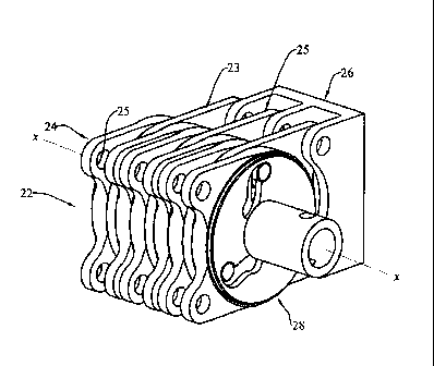
folded positions, but
is relatively large, heavy and expensive to manufacture. The F-35, with a
thinner wing,
cannot accommodate this type of hinge design due to a reduced envelope. Hence,
a spline
=
lock concept of driven hinge, such as shown in U.S. Pat. No. 6,032,418, has
been developed.
This provides a smaller-profile hinge lock, and an overall lighter design.
However, it also
requires tighter tolerances and difficult machining of the hinge actuator
parts, as well as the
mating aircraft structure.
[0005] Accordingly, it would be generally desirable to provide an
improved powered
hinge that would have an automatic locking feature at either end of the
permissible relative
CA 02658785 2013-07-04
=
63109-502
2
angular displacements of its hinge sections, that would be lighter in weight,
and that would be
less expensive to manufacture.
Disclosure of the Invention
[0006] With parenthetical reference to the corresponding parts,
portions or surfaces of
the disclosed embodiment, merely for purposes of illustration and not by way
of limitation,
some embodiments of the present invention broadly provide a powered hinge (20)
with an
automatic locking feature proximate the ends of the permissible relative
angular displacement
of the two hinge sections.
[0007] The hinge broadly includes: a stationary member (23) having a
pivotal axis
(x-x), and having a first slot (31) extending between opposite ends; a movable
member (24)
mounted for rotation about the pivotal axis relative to the stationary member,
and having a
second slot (34) extending between opposite ends; a driving member (28)
adapted to be
rotated about the pivotal axis relative to the stationary member from one
angular position to
another angular position, and having a third slot (36) extending between
opposite ends; and an
elongated pin (29) passing through the first, second and third slots, the pin
being constrained
for movement substantially parallel to the pivotal axis; the first, second and
third slots being
so configured and arranged that as the driving member is rotated from the one
angular
position to the other angular position, the pin will be moved from
substantially one end of the
each of the slots to substantially the other end of each of the slots, and the
movable member
will be rotated about the pivotal axis relative to the stationary member.
[0008] The ratio of the angular movement of the movable member to the
angular
movement of the driving member may be greater than 1:1.
[0009] The hinge may further include driving means (21) for
selectively rotating the
driving member relative to the stationary member.
[0010] Each of the members may be a plate-like element. The hinge may
include a
plurality of the stationary and movable members arranged in an alternating
series. The pin
CA 02658785 2013-07-04
63109-502
2a
may be arranged to transmit torque in double-shear. In the preferred
embodiment, there are at
least two of the driving members. A shaft (35) may connect each of the driving
members.
[0011] In the preferred form, the stationary member is provided with
a plurality of the
first slots, the movable member is provided with a plurality of second slots,
and the driving
member is provided with a plurality of third slots, and the improved hinge
further includes a
like plurality of pins.
[0012] One of the slots preferably has a recess proximate an end
thereof to function as
a detent to prevent the penetrant portion of the pin from moving in a radial
direction with
respect to the pivotal axis when the penetrant pin portion is substantially at
such slot end.
Each of the first and third slots may have this recess, and the second slot
may extend in a
radial direction.
[0012a] Another embodiment of the present invention provides a hinge,
comprising: a
stationary member having a pivotal axis, and having a first slot extending
between opposite ends;
a movable member mounted for rotation about said pivotal axis relative to said
stationary
member, and having a second slot extending between opposite ends; a driving
member adapted to
be rotated about said pivotal axis relative to said stationary member from one
angular position to
another angular position, and having a third slot extending between opposite
ends; and an
elongated pin passing through said first, second and third slots, said pin
being constrained for
movement substantially parallel to said pivotal axis; said first, second and
third slots being so
configured and arranged that as said driving member is rotated from said one
angular position to
said other angular position, said pin will be moved from substantially one end
of said each of said
slots to substantially the other end of each of said slots, and said movable
member will be rotated
about said pivotal axis relative to said stationary member.
CA 02658785 2013-07-04
63109-502
3
[0013] Better yet, the one slot may have a recess proximate each end
thereof to
function as detents to prevent the penetrant portion of the pin from moving in
a radial
direction with respect to the pivotal axis when the penetrant pin portion is
substantially at
either end of the slot. Each of the first and third slots may have the recess
proximate each end
thereof, and the second slot may be oriented in a radial direction with
respect to the pivotal
axis.
[0014] Accordingly, the general embodiment may provide a powered
hinge.
[0015] Another embodiment may provide a powered hinge having an
automatic
locking feature proximate the ends of permissible relative movement between
the two hinge
1 0 sections.
[0016] Another embodiment may provide a powered hinge having such an
automatic
locking feature, which is less expensive to manufacture and produce.
Brief Description of the Drawings
located in the middle of two hinge portions.
[0019] Fig. 2 is a greatly-enlarged isometric view of a portion of
the improved driven
hinge, this view showing the stationary members, the movable members, the
driving
members, and the pins.
[0021] Fig. 4 is an isometric view of the stationary members and pins
shown in Fig. 2.
[0022] Fig. 5 is an isometric view showing the movable members and
pins shown
in Fig. 2.
CA 02658785 2013-07-04
63109-502
3a
[0023] Fig. 6 is a schematic end view of the various members, showing
the profiles of
the first, second and third slots in the stationary, movable and driving
members, respectively,
at various angular positions of the movable member relative to the stationary
member.
[0024] Fig. 7 is an end view of the powered hinge, schematically
showing the profile
of the first, second and third slots.
[0025] Fig. 8 is a top plan view of the improved hinge, without the
driving means.
[0026] Fig. 9 is a fragmentary longitudinal sectional view of the
powered hinge, taken
generally on line 9-9 of Fig. 8, and principally showing the input shaft as
connecting the
various driving members.
CA 02658785 2009-01-23
WO 2008/024178 PCT/US2007/017037
4
Disclosure of the Preferred Embodiments
. . .
[0027] At the outset, it should be clearly understood that like reference
numerals are in-
tended to identify the same structural elements, portions or surfaces
consistently throughout
the several drawing figures, as such elements, portions or surfaces may be
further described
or explained by the entire written specification, of which this detailed
description is an inte-
gral part. Unless otherwise indicated, the drawings are intended to be read
(e.g., cross-
hatching, arrangement of parts, proportion, degree, etc.) together with the
specification, and
are to be considered a portion of the entire written description of this
invention. As used in
the following description, the terms "horizontal", "vertical", "left",
"right", "up" and "down",
as well as adjectival and adverbial derivatives thereof (e.g., "horizontally",
"rightwardly",
"upwardly", etc.), simply refer to the orientation of the illustrated
structure as the particular
. .
drawing figure faces the reader. Similarly, the terms "inwardly" and
"outwardly" generally
refer to the orientation of a surface relative to its axis of elongation, or
axis of rotation, as ap-
propriate.
[0028] The present invention broadly provides an improved powered hinge having
an
automatic locking feature proximate either end of the permissible relative
angular displace-
ment of its hinge sections. The present invention may be used on an aircraft
wingfold. How-
ever, the invention has utility far broader then this one specific
application. Accordingly, the
invention should not be regarded as being limited to this particular end use.
[0029] Referring now to the drawings, the improved powered hinge is generally
indicated
at 20. As best shown in Fig. 1, the hinge is shown as having a driving means
21 operatively
arranged in the middle of two hinge portions, severally indicated at 22. Each
hinge portion
has a plurality of axially spaced stationary members, severally indicated at
23, and movable
members, severally indicated at 24. The driving means 21 is operatively
arranged to selec-
tively rotate a shaft, described infra, by means of which the various movable
hinge members
22 may. be selectively rotated about the pivotal axis (x-x) relative to the
various stationary
hinge members 23, as described infra.
[0030] Fig. 2 is an isometric view of a portion of one of the hinge parts.
Here again, the
stationary members are indicated at 23, and the movable members are indicated
at 24. As can
be seen, the powered hinge has a pivotal axis x-x. A plurality of stationary
hinge sections 23
are spaced along axis x-x, and a plurality of movable hinge sections 24 are
positioned be-
tween the various stationary sections. Each of the stationary and movable
sections are shown
as having suitable eyes, severally indicated at 25, by means of which the
associated hinge
CA 02658785 2009-01-23
WO 2008/024178 PCT/US2007/017037
section may be attached to other structure. In Fig. 2, the stationary hinges
are depicted as be-
ing attached to a suitable support, generally indicated at 26.
[0031] As best shown in Figs. 2 and 3, the improved hinge is also shown as
further includ-
ing a plurality of driving members, severally indicated at 28, and cylindrical
pins, severally
indicated at 29.
[0032] Fig. 4 is an isometric view showing the various stationary members 23
and pins 29.
In other words, the driving members 28 and movable members 24 have been
removed from
Fig. 4 to more clearly illustrate the stationary members and the pins.
[0033] Fig. 5 is an isometric view depicting the movable members 24 and pins.
In other
words, the stationary members 23 and the driving members 28 have been removed
from Fig.
5 to more clearly illustrate the structure of the movable members and the
pins.
[0034] Adverting now to Fig. 4, each stationary member 23 is shown as being a
somewhat
plate-like member, having a central axial aperture 30, and having three
circularly-spaced spe-
cially-configured first slots, severally indicated at 31. These slots, which
are shown more
clearly in elevation of Fig. 6, have a somewhat S-shaped appearance, and have
recesses 32
proximate either end thereof. These recesses function as detents to receive
the various pins at
the ends of the permissible angular displacements of the stationary and
movable hinge mem-
bers.
[0035] Referring now to Fig. 5, the various movable members 24 are shown as
being plate-
like elements having central axial through aperture 33, and having three
radially-disposed
second slots, severally indicated at 34.
[0036] Referring now to Fig. 3, each driving member 28 is shown as having a
central axial
aperture 35, and is provided with three circularly spaced third slots,
severally indicated at 36.
As with the stationary members, slots 36 have recesses, indicated at 38
proximate either end,
that function as detents to receive and hold pins 29 proximate the end of
their permissible an-
gular displacements.
[0037] There are three pins, severally indicated at 29, that have passed
through the aligned
first, second and third slots in the stationary, movable and driving members,
respectively.
These various pins are constrained to move in the various slots and remain
substantially par-
allel to the pivotal axis x-x and all permissible locations thereof.
[0038] Fig. 6 is a schematic view showing the first, second and third slots,
and the position
of a pin therein, at both extreme positions of movement of the movable member
relative to
the stationary member, as well as at an intermediate position. In the 12
o'clock position, pin
CA 02658785 2009-01-23
WO 2008/024178 PCT/US2007/017037
6
29 is positioned at being in the recess adjacent the upper end of the third
slot, and as posi-
tioned in the recess adjacent the upper end of the first slot, and as being at
the upper end of
the second slot.
[0039] The driving means 21 may then be operated to selectively rotate the
driving mem-
bers relative to the stationary members. In the 3 o'clock position of Fig. 6,
the pin is shown
as having moved to the other and inner end of the third slot, the inner end of
the second slot
and the inner end of the first slot. More particularly, at the 3 o'clock
position, the pin is
shown as being in the recesses of the first and third slots. At the 1:30
o'clock position, the pin
is shown as being at an intermediate position between the two extremes shown
at the 12
o'clock and 3 o'clock positions, respectively.
[0040] The principal function of the recess proximate the ends of the first
and third slots is
to provide a detent to prevent the pin from moving in a radial direction
(i.e., either inwardly
or outwardly) when the hinge sections are at there extreme permissible angular
positions.
This has the feature of practically locking the two hinge sections at their
extreme positions.
[0041] Fig. 7 is a view of the powered hinge, again showing the profiles of
the first, second
and third slots and the positions of the pins therein. The position of the pin
shown in Fig. 7
corresponds to the position of the pin shown at the 12 o'clock position in
Fig. 6.
[0042] Fig. 8 is a top plan view of the driven hinge section 22, showing the
stationary and
movable members.
[0043] Fig. 9 is a fragmentary longitudinal sectional view, showing an input
shaft 35 as
being concentric with pivotal axis x-x, and is operatively connecting a
plurality of driving
members that are interspaced within the stack of the alternating stationary
and movable
members, this view also showing one of the pins.
[0044] Therefore, the present invention broadly provides an improved powered
hinge
which broadly includes a stationary member having a pivotal access and having
a first slot
extending between opposite ends; a movable member mounted for rotation about
the pivotal
access relative to the stationary member, and having a second slot extending
between oppo-
site ends; a driving member adapted to be rotated about the pivotal axis
relative to the sta-
tionary member from one angular position to another angular position, and
having a third slot
extending between the opposite ends; and an elongated pin passing through the
first, second
and third slots, the pin being constrained for movement substantially parallel
to the pivotal
access; the first, second and third slots being so configured and arranged
that, as the driving
member is rotated from one angular position to another angular position the
pin will be
CA 02658785 2013-07-04
63109-502
7
moved from substantially one end of each of the slots to substantially the
other end of each of
the slots, and the movable member will be rotated about the pivotal axis
relative to the sta-
tionary member.
[0045] In the disclosed embodiment, the ratio of angular movement of the
movable mem-
ber to the angular movement to the driving member is greater than 1:1.
Modifications
[0046J The present invention expressly contemplates that various changes and
modifica-
tions may be made. For example, while it is presently preferred that the
various stationary,
movable and driving members may be plate-like elements so that they may be
stacked as
shown in the drawings, this arrangement can be varied. The shape and
configuration of first,
second and third slots may also be varied. As used herein, the word slot is
intended to simply
define a narrow opening which defines a path of movement for the pin. The
various slots
= may or may not have recesses at either end that function as detents to
lock the pins against
radial movement at the extreme ends of the permissible movement of the hinge
sections.
[0047] Therefore, while the presently-preferred form of the improved powered
hinge has
been shown and described, and several modifications thereof discussed, persons
skilled in
this art will readily appreciate that various additional changes and
modifications may be
made without departing from the scope of the invention, as defined and
differentiated by the
following claims.