Note : Les descriptions sont présentées dans la langue officielle dans laquelle elles ont été soumises.
CA 02659776 2009-02-03
WO 2008/014557 PCT/AU2007/001081
1
"A catheter handle assembly"
Cross-Reference to Related Applications
The present application claims priority from United States of America
Provisional Patent Application No 60/835,501 filed on 4 August 2006, the
contents of
which are incorporated herein by reference.
Field
This invention relates, generally, to catheters and, more particularly, to a
modular catheter assembly, to catheter handle assembly and to components for a
modular catheter assembly.
Background
Catheters, such as those used in cardiovascular applications, are comprised of
an
elongate electrode carrying element mounted on a distal end of a handle. The
handle
has at least one connector so that a patient cable can be connected to a
proximal end of
the handle to feed signals through the handle to the electrodes. Often, these
catheters
include steering mechanisms or stylets arranged within the electrode carrying
element
to effect steering of a distal end of the electrode carrying element.
Such an arrangement results in an expensive piece of equipment particularly
the
handle which has the at least one connector and cabling. Also, because of
voids in the
electrode carrying element and in the interior of the handle, it is not
possible, generally,
to effect sufficient sterilisation of such catheters to allow them to be
reused. Thus, in
most cases, the catheters are used once only and are then disposed of.
Not only does this create a substantial expense but there is the environmental
problem of disposal of potentially hazardous items.
Summary
According to one aspect of the invention, there is provided a catheter handle
assembly which includes
a holder having a proximal end and a distal end;
an electrode sheath carrier arranged at the distal end of the holder;
a shape imparting element carrier removably mountable to the proximal end of
the holder, the shape imparting element carrier having at least one mounting
formation
for mounting at least a part of a shape imparting element; and
CA 02659776 2009-02-03
WO 2008/014557 PCT/AU2007/001081
2
a slide displaceably arranged in the holder with a distal end of the slide
mounting the electrode sheath carrier and a proximal end of the slide
terminating in
proximity to the shape imparting element carrier.
The holder may taper inwardly from its proximal end to its distal end. An
abutment may be arranged on the holder to provide purchase for a user's hand.
This
arrangement improves the balance and the ergonomics of the handle assembly.
The shape imparting element carrier may comprise a manipulating element and
a receiving member, for receiving a further part of the shape imparting
element,
slidably received in an end of the manipulating element. Further, the
manipulating
element and the receiving member may include locating formations receivable in
complementary receiving formations of the holder and the slide, respectively.
The
locating formations and receiving formations may be complementary bayonet type
fittings.
Preferably, the slide includes a guide arrangement arranged in proximity to
its
receiving formation, the guide arrangement guiding the shape imparting element
into a
proximal end of the slide. The guide arrangement may be in the fozm of a
funnel
shaped member for guiding the shape imparting element into the slide.
The slide may include a body member which supports a guide member
extending distally from the guide arrangement. The guide member may be a
primary
guide tube supported by the body.
A secondary guide member may extend proximally from the electrode sheath
carrier, the secondary guide member cooperating with the guide member of the
slide
for guiding and supporting the shape imparting element in the holder.
Likewise, the
secondary guide member may be a secondary guide tube which is slidably
received
over the primary guide tube.
A distal part of the body member may be tubular and may project from a distal
end of the holder, the electrode sheath carrier being slidably received on a
distal portion
of the tubular part. With this arrangement, the electrode sheath carried, in
use, by the
electrode sheath carrier can be extended and retracted relative to the shape
imparting
element received in a lumen of the electrode sheath. Thus, a distal end of the
electrode
sheath, the distal end carrying electrodes, can be manipulated by the
clinician to be
inserted into difficult to reach sites in a patient's body and/or to enhance
tissue/electrode contact.
The tubular part may include a proximal portion arranged in the distal end of
the
holder, the proximal portion being separated from the distal portion by a
mount, a slide
CA 02659776 2009-02-03
WO 2008/014557 PCT/AU2007/001081
3
control member being carried by the mount. For ease of moulding the slide
control
member may be a separate element which is a tight fit on the mount.
The proximal portion and the distal portion of the tubular part may each carry
a
friction inducing component for increasing friction between the slide and the
holder
and between the slide and the electrode sheath carrier respectively. The
friction
inducing components may be friction pads carried on opposed sides of the
mount.
The electrode sheath carrier may carry an adaptor which facilitates the
insertion
of the shape imparting element through the electrode sheath carrier. Further,
the
electrode sheath carrier may include an adaptor carrying a closure element for
inhibiting back flow of fluid into the holder.
The manipulating element may have a substantially paddle shaped handle
projecting axially from the holder. A proximal end of the holder and the
manipulating
element may define an access opening through which at least one of a bundle of
electrical conductors and a conduit can pass.
According to a second aspect of the invention, there is provided an electrical
lead which includes
a lumen defining member, the lumen defining member having a discontinuity
along its length to create a proximal part and a distal part;
a plurality of conductors carried on an outer surface of the lumen defining
member, the conductors being separated from the lumen defining member at the
discontinuity to enable access to be gained to a part of the lumen defined by
the distal
part, the plurality of conductors electrically bridging the discontinuity; and
at least one electrode carried on the distal part of the lumen defining
member.
The electrical lead may be intended for use with the catheter handle assembly
as
described above, a proximal end of the distal part being secured to a distal
end of the
electrode sheath carrier, the electrode sheath carrier defining a passage
through which
the proximal part of the lumen defining member and a bundle of the conductors
pass to
extend internally within the holder and to exit through the proximal end of
the holder.
Brief Description of Drawings
Fig. 1 shows a three dimensional, rear view of a catheter handle assembly, in
accordance with an embodiment of the invention;
Fig. 2 shows a three dimensional, exploded view of the handle assembly;
Fig. 3 shows a sectional plan view of the handle assembly;
Fig. 4 shows a sectional side view of the handle assembly taken along line IV-
IV in Fig. 3;
CA 02659776 2009-02-03
WO 2008/014557 PCT/AU2007/001081
4
Fig 5 shows, on an enlarged scale, the encircled part of Fig. 3;
Fig 6 shows, on an enlarged scale, the encircled part of Fig. 4;
Fig. 7 shows a sectional plan view of a shape imparting element carrier of the
handle assembly; and
Fig. 8 shows a schematic representation of an electrical lead, in accordance
with
another embodiment of the invention.
Detailed Description of Exemplary Embodiment
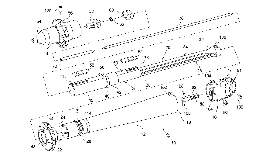
In the drawings, reference numeral 10 generally designates a catheter handle
assembly, in accordance with an embodiment of the invention. The handle
assembly
10 includes a tubular holder. An electrode sheath carrier 14 is mounted
distally of the
holder 12. A shape imparting element carrier or knob 16 is arranged at a
proximal end
18 of the holder 12. A slide 20 (Figs. 2 to 4) is received within an interior
22 of the
holder 12.
The holder 12 tapers inwardly from its proximal end 18 to a distal end 24. An
abutment 26 is arranged on the holder 12 proximally of the distal end 24 of
the holder
12 to provide purchase for a clinician's hand when manipulating the handle
assembly
10. The tapered nature of the holder 12 and the abutment 26 provide a balanced
handle
assembly 10 which facilitates manipulation by the clinician.
The slide 20 comprises a body member 28 terminating in an enlarged, tubular
part 30. A guide mechanism in the form of a funnel shaped member 32 is
arranged at a
proximal end of the body member 28. The funnel shaped member 32 assists in
inserting a shape imparting element (not shown) into the proximal end of the
slide 20.
The body member 28 has a longitudinally extending, centrally located slot 34
extending from the funnel shaped member 32. A metal tube 36, which acts as a
primary guide tube, is received in the slot 34 and is secured in position, for
example, by
an appropriate adhesive. The tube 36 projects into the tubular portion 30 as
shown in
greater detail in Figs. 3 and 4 of the drawings.
The enlarged, tubular part 30 of the body member 28 has a proximal portion 3,8
and a distal portion 40 separated by a radially raised mount 42. The mount 42
and the
distal portion 40 of the tubular part 30 of the slide 20 project from the
distal end 24 of
the holder 12. A slide control member 44 is mounted on the mount 42. For ease
of
moulding, the slide control member 44 is removably mounted on the knob 42 and
is
adhered in position. It will, however, be appreciated that, with suitable
moulding
techniques, the slide control member 44 could be moulded with the body member
28 as
a one-piece moulding.
CA 02659776 2009-02-03
WO 2008/014557 PCT/AU2007/001081
A distal end of the mount 42 defines an annular locating rib 46 which is
received
in a complementary annular groove 48 of the slide control member 44. This
serves to
locate the slide control member 44 relative to the mount 42.
It is also to be noted that the tubular part 30 of the slide 20 has flats 50
defined
5 on both the proximal portion 38 and the distal portion 40. The flats 50
carry friction-
inducing components in the form of friction pads 52. The proximal friction pad
52
induces friction between the slide 20 and the interior 22 of the holder 12 and
the distal
friction pad 52 induces friction between the slide 20 and the electrode sheath
carrier 14,
The electrode sheath carrier 14 comprises a nose cone-like element 54 which
has a control member 56 formed integrally therewith as a one-piece unit. The
electrode
sheath carrier 14 is slidably mounted on the distal portion 40 of the tubular
part 30 of
the slide 20. With this arrangement the electrode sheath carrier can be
displaced axially
with respect to the remainder of the holder 12. This allows an electrode
sheath (not
shown) carried by the electrode sheath carrier 14 to be displaced relative to
a shape
imparting element received in a lumen of the electrode sheath. The electrode
sheath is
manufactured according to the Applicant's manufacturing technique as described
in the
Applicant's International Application Number PCT/AU01/01339 dated 19 October
2001 and entitled "An electrical lead". A benefit of the manufacturing
technique is that
an electrode sheath results having an unimpeded lumen. This results from the
conductors for electrodes of the electrode sheath being helically wound about
an outer
surface of a lumen defining component of the electrical lead. In other words,
the
conductors do not extend through the lumen of the electrical lead. The shape
imparting
element can therefore be inserted into the lumen of the electrode sheath via
the
electrode sheath carrier.
A frusto-conical guide member 58 is received within the electrode sheath
carrier
14 to guide insertion of the shape imparting element through the electrode
sheath
carrier 14.
An adaptor 60 is, optionally, secured to a proximal end of the guide member
58.
The adaptor 60 is used when a catheter with which the handle assembly 10 is
used
includes irrigation. Thus, the adaptor 60 mounts a closure member in the form
of a
membrane 62. The membrane 62 is pierced by the shape imparting element when it
is
inserted through the handle assembly 10. The membrane 62 is of the type which
reseals upon withdrawal of the shape imparting element to inhibit the ingress
of fluids
into the interior of the handle assembly 10.
The guide member 58 and the adaptor 60 define grooves 64 and 66 (Figs. 3 and
5), respectively, in which a distal portion of a proximal part of an
electrical lead, a
CA 02659776 2009-02-03
WO 2008/014557 PCT/AU2007/001081
6
distal part of which forms the electrode sheath, as will be described in
greater detail
below, is received with the proximal part passing through the holder 12 to
exit through
an opening, or slot, 76 (Fig. 3) at the proximal end 18 of the holder 12. The
groove 64
opens into a central bore 67 defined through the electrode sheath carrier 14
at a junction
64.1, as shown in Fig 6 of the drawings. A proximal end of the bore 67 is
occluded by
the membrane 62 as shown most clearly in Fig 5 of the drawings.
The adaptor 60 also defines a socket 69 (Fig. 5) into which a distal end of an
irrigation tube (not shown) is inserted to be in fluid communication with the
bore 67 of
the electrode sheath carrier 14. The irrigation tube also passes through the
interior of
the holder 12 and exits the holder 12 through the opening 76.
Further, it is to be noted in Figs. 3-6 of the drawings that a proximal end of
the
guide member 58 has a funnel-shaped opening 70 which aids in inserting the
shape
imparting element through the guide member 58 to exit the electrode sheath
carrier 14.
A secondary guide tube 72 extends proximally from the electrode sheath carrier
14. In the case where the adaptor 60 is provided, the secondary guide tube 72
extends
from a proximal side of the adaptor 60. In the case where the adaptor 60 is
omitted, the
tube 72 is mounted to a proximal end of the guide member 58.
The tube 72 is slidably received over the primary guide tube 36 to assist in
maintaining accurate axial displacement of the electrode sheath carrier 14
relative to
the distal portion 40 of the tubular part 30 of the slide 20 as the electrode
sheath carrier
14 is displaced axially relative to the slide 20.
In an embodiment, the handle assembly 10 is intended for use with a shape
imparting element in the form of a steering shaft. The steering shaft is
omitted from the
drawings. The steering shaft is of the type having an outer tubular element
and an inner
actuator received in a passage of the tubular member. The actuator and the
tubular
member are fast with each other at a connection at a distal region of the
steering shaft.
The tubular member defines a bend-enhancing region proximally of the
connection of
the tubular member and the actuator so that when there is relative axial
displacement
between the tubular member and the actuator occurs, bending of the tubular
member
about the bend-enhancing region occurs. The steering shaft is described in
greater
detail in the Applicant's co-pending International Patent Application No.
PCT/AU2005/000216 dated 18 February 2005 and entitled "A steerable catheter".
Referring to Fig. 7 of the drawings, the knob 16 is described in greater
detail.
The knob 16 has a boss 74 which is received in the proximal end 18 of the
holder 12
and is generally shaped to be a snug fit within the proximal end 18 of the
holder 12.
However, as shown most clearly in Fig. 1 of the drawings, a part of the boss
74 is cut
CA 02659776 2009-02-03
WO 2008/014557 PCT/AU2007/001081
7
away to define the access opening or slot 76 through which the electrical lead
(described in greater detail below with reference to Fig. 8 of the drawings)
and the
irrigation tube, if applicable, pass.
A paddle-shaped handle 77 projects proximally from the boss 74. The paddle-
shaped handle 76 defines a passage 78 opening out into a wider passage 80 in
the boss
74. The boss 74 and the handle 77 together form a manipulating element 81.
A receiving member 82 which receives the outer, tubular member of the steering
shaft is axially, slidably received in the passage 80 of the manipulating
element 81.
The receiving member 82 defines a bore 84 within which the tubular member of
the
steering shaft fits snugly. The receiving member 82 is held slidably captive
in the
passage 80 by means of a grub screw 86 which is received through the boss 74
into an
axially extending, blind groove 88 defined in a side of the receiving member
82. As
shown more clearly in Figs. 2 to 4 of the drawings, the receiving member 82 is
of
polygonal, more particularly, square cross section, to inhibit rotation of the
receiving
member 82 relative to the manipulating element 81. Accordingly, the passage 80
is of
a corresponding polygonal cross section.
Packing 90, in the form of a plurality of nested tubes 92, 94 and 96, is
arranged
in the passage 78 and receives the actuator of the steering shaft therein. It
is to be noted
that, if desired, the packing 90 can be omitted or can be of fewer tubes to
accommodate
the actuator of the steering shaft. The packing 90 defines an annular groove
98 in
which a grub screw 100 is received for locking the actuator of the steering
shaft to the
manipulating element 16.
The proximal end 18 of the holder 12 has a pair of opposed receiving
formations, each in the form of an L-shaped slot 102. One of the slots 102 is
shown
more clearly in Figs. 1 and 2 of the drawings. The manipulating element 81 has
a pair
of opposed locating formations, in the form of opposed radially outwardly
extending
pins 104. The pins 104 are received in the slots 102 and, by turning the
manipulating
element 81 through a predetermined arc after insertion of the pins 104, the
manipulating element 81 is locked to the proximal end 18 of the holder 12.
Similarly, as shown in greater detail in Fig. 4 of the drawings, a proximal
end of
the body member 28 of the slide 20 has a pair of opposed receiving formations
each of
which, once again, is in the form of an L-shaped slot 106. One of the slots
106 is
shown in more clearly in Fig. 2 of the drawings.
The receiving member 82 carries, at its distal end, a pair of opposed locating
formations in the form of a pair of opposed outwardly extending pins 108. The
pins
108 are received in the slots 106, when the slide 20 is fully at its proximal
position
CA 02659776 2009-02-03
WO 2008/014557 PCT/AU2007/001081
8
within the holder 12. This locks the receiving member 82 to the slide 20 to
move with
the slide 20 as the slide 20 is displaced under the action of the slide
control member 44.
As described in greater detail in the Applicant's co-pending International
Application
No. PCT/AU2005/000216, referred to above, when the actuator of the steering
shaft
and the tubular element of the steering shaft are moved relative to each
other, a bending
action is effected at a distal end of the steering shaft. Thus, by relative
movement
between the receiving member 82 and the manipulating element 16 under the
effect of
the slide 20, this bending action is achieved.
The proximal friction pad 52 has a tab 110 (Fig. 4) projecting from an
operatively lower surface to be received in a groove 112 in the proximal
portion 38 of
the tubular part 30 of the slide 20. The friction pad 52 is located in
position by a grub
screw 114 and also locates the slide 20 relative to the holder 12.
Similarly, the distal friction pad 52 has a tab 116 on its lower surface which
is
received in a groove 118 in the distal portion 40 of the tubular part 30 of
the slide 20.
The distal friction pad 52 is secured relative to the electrode sheath carrier
14 via a grub
screw 120 and also locates the electrode sheath carrier 14 relative to the
distal portion
40 of the tubular part 30 of the slide 20. It will be appreciated that, with
this
arrangement, axial sliding movement of the slide 20 relative to the holder 12
is effected
and, similarly, axial sliding movement of the electrode sheath carrier 14
relative to the
slide 12 is effected. These frictionally restricted movements are governed by
the
friction pads 52.
It is intended that the handle assembly 10 will, largely, be a one-use device
which will be disposed of. However, the knob 16 comprising the manipulating
element
81 and the receiving member 82 are reused. Thus, the manipulating element 81
is of a
sterilisable or heat resistant plastics material or a metal, such as titanium
or stainless
steel, while the receiving member 82 is of a metal which can be heat treated.
The knob
16 and the receiving member 82 are re-used while the remainder of the handle
assembly 10 is disposed of after a single use,
Referring now to Fig. 8 of the drawings, an embodiment of an electrical lead
is
illustrated and is designated generally by the reference numeral 130. The
electrical
lead 130 is substantially greater in length than the length of electrode
sheath required
for use as a catheter. The electrical lead 130 has a distal part 132 which is
of the
requisite length and forms the electrode sheath of the catheter. Conductors
136 are
wound around the lumen defining member 134, for normal use. At a proximal end
of
the electrode sheath portion 132, a lumen defining member 134 of the
electrical lead is
accessed by unwinding the conductors 136 from the lumen defining member 134.
By
CA 02659776 2009-02-03
WO 2008/014557 PCT/AU2007/001081
9
unwinding the conductors 136 and separating the lumen defining member 134 to
form a
discontinuity 135 in the lumen defining member 134, access can be gained to a
lumen
138 of the lumen defining member 134 of the distal part 132. A proximal end of
the
distal part 132 is, in use, secured to a distal end of the electrode sheath
carrier 14.
The remaining, proximal part 140 of the electrical lead 130, with its
conductors
136 wound about it, forms an electrical cable of the catheter and passes via
the grooves
64 and 66 of the guide member 58 and the adaptor 60, respectively, and passes
internally through the holder 12 to exit through the slot 76 defined between
the
manipulating element 81 and the proximal end 18 of the holder 12. An
electrical
connector 142 is connected to the proximal end of the proximal part 140 of the
electrical lead 130 for connection to a patient cable or other equipment (not
shown).
It will be noted that a distal end of the distal part 132 of the electrical
lead 130
carries electrodes 144 thereon. Further, due to the construction of the guide
member 58
and, optionally, the adaptor 60, when the electrode sheath carrier 14 is
displaced
relative to the slide 20, the entire lead 130 moves together with the
electrode sheatll
carrier 14.
It is a particular advantage of the invention that a handle assembly 10 is
provided which is ergonomically sound and balanced to provide ease of use for
a
clinician. It is a further advantage of the invention that a handle assembly
10 is
provided which facilitates the passage of conductors and/or irrigation tubes
internally
through the handle assembly 10. Thus, the likelihood of these cables and/or
irrigation
tubes getting in the way are reduced. This is facilitated by the construction
of the
electrical lead 130.
It is still a further advantage of the invention that a handle assembly 10 is
provided which has a reusable part thereby reducing costs and minimising
damage to
the environment. In this regard, it is to be noted that the holder 12, the
electrode sheath
14 and the slide 20 are low-cost items which can be disposed of after one use
and, if
possible, can be recycled. These parts do not carry any electrically
conductive material
therein. This facilitates disposal of these parts and their recycling.
In addition, the absence of an electrical connector at the distal end of the
handle
assembly 10 facilitates insertion of the shape imparting element into the
lumen-defining
part 134 of the electrical lead 130 attached to the electrode sheath carrier
14. The ease
of insertion of the shape imparting element is further facilitated by the
construction of
the proximal part of the slide 20 and the guide member 58 of the electrode
sheath
carrier 14.
CA 02659776 2009-02-03
WO 2008/014557 PCT/AU2007/001081
Still further, the facility of having the electrode sheath displaceable
relative to
the shape imparting element assists a clinician to position the electrodes at
hard to
reach locations at a site in the patient's body and/or to improve
tissue/electrode contact
at the site. The fact that the part of the electrical lead witllin the holder
12 moves with
5 electrode sheath carrier 14 improves the ease of use of the handle assembly
10.
It will be appreciated by persons skilled in the art that numerous variations
and/or modifications may be made to the invention as shown in the specific
embodiments without departing from the spirit or scope of the invention as
broadly
described. The present embodiments are, therefore, to be considered in all
respects as
10 illustrative and not restrictive.