Note : Les descriptions sont présentées dans la langue officielle dans laquelle elles ont été soumises.
CA 02661560 2009-02-24
WO 2008/023187 PCT/GB2007/003229
VELOCITY DETECTOR
Field Of The Invention
This invention relates to a velocity detector for measuring the velocity of an
object
passing through a defined field of view.
Background To The Invention
In the prior art a technique known as Laser Doppler Velocimetry ("LDV") uses
the
coherent nature of laser light to focus two crossing laser beams with
identical
polarisation at a single reference point, thereby creating linear and
regularly spaced
interference fringes within a defined measurement volume. An object passing
through
the measurement volume will reflect incident light from the fringes back to a
detector
via a lens system and produce a signal that can be interpreted to deliver the
velocity of
the object. The signal frequency will relate to the fringe spacing and the
velocity of the
object. For precision laser beam geometry, fringe spacing is highly regular,
allowing
accurate velocity measurements to be made. An instrument using this technique
is
commonly known as a Velocimeter.
For two laser beams emerging from the final focussing lens of a velocimeter at
spacing
L and each having a beam diameter S, and where II is the mathematical constant
Pi
(3.14159...), the number of fringes N generated in the measurement volume at
the
crossing point of the two beams is given by the formula:
N = 4/II * L/S
For laser beams of wavelength 2 and a focusing lens of focal length f, the
diameter D of
the measurement volume is given by the formula:
D = 4/II * U/S
It will be appreciated by those skilled in the art that a focused laser beam
forms a `beam
waist' at the point of focus of finite diameter D and length.
CA 02661560 2009-02-24
WO 2008/023187 PCT/GB2007/003229
2
As an example, and to illustrate the later discussion, consider a focusing
lens of focal
length of 250mm and a pair of laser beams with a beam spacing of 45mm, beam
diameter of 2mm and a wavelength k = 780nm. The number of fringes N and the
measurement volume diameter D are thus:
N = 4/11 * L/6 D = 4/II * kf/8
N = 1.273 * 45/2.0 D = 1.273 * 780 * 10-9 * 250/2.0
N = 28 fringes D = 124 microns
This gives a fringe spacing in the measurement volume of D/N = 4.4 microns.
The orientation of the fringes in relation to a given polarisation axis of the
laser beams
is fixed, such orientation being a function of the interference effect which
creates the
fringes.
If the two laser beams do not cross precisely at their focus (known as the
"beam
waist"), the geometric regularity of the fringes will be compromised, and the
fringe
spacing will vary throughout the length of the measurement volume. An object
travelling at a constant velocity will therefore create different frequencies
as it passes
through different parts of the measurement volume, an undesirable effect. In
the above
example, the measurement volume length will be less than 1mm, and the
manufacturing
precision of the lenses and optical components used in the velocimeter must of
necessity be of a very high standard (and therefore expensive) to achieve
consistency of
fringe spacing.
Using the above example, an object passing through the measurement volume will
produce a signal with a velocity constant Fout determined by
Fout = N/D
Fout = 0.227 * 106 Hz/metres/second
As velocimetry can be used to measure the velocity of high speed particles
with very
small sizes (sometimes having sub-micron diameters), the sensitivity of the
detectors
used must be high, as the amount of light scattered by the particle as it
passes through a
fringe will be small. In order to measure high velocities, the bandwidth of
the detectors
CA 02661560 2009-02-24
WO 2008/023187 PCT/GB2007/003229
3
used must also be high. The gain-bandwidth product of the detector will
therefore be
high, increasing the cost. In a limiting case, the cost of the detector
required might be
so high as to render the use of velocimetry uneconomic for some applications.
Again in the above example, a detector with sufficient sensitivity to measure
(say) high
speed smoke and debris efflux in the 1 - 3 micron diameter range from a small
rocket
motor might only have a bandwidth of 10MHz. The maximum velocity capable of
being measured would therefore be 10/0.227 = 44 metres/second. However,
combustion efflux velocities can easily reach several hundred metres/second,
and for
very powerful rockets, velocities of several thousand metres/second can be
encountered. The bandwidth limitation would not allow the instrument to be
used.
As the direction of the passing object relative to the velocimeter might vary,
or in some
circumstances might not be known, it may be necessary to rotate the entire
velocimeter
to ensure that the orientation of the fringes is at right angles to the object
path. This
may not always be possible, or in turn might cause the laser beams to collide
with other
(unspecified) objects within the field of view of the instrument, causing
unwanted
backscatter of laser light into the instrument.
Summary of the Invention
According to a first aspect of the present invention there is provided a
method of
detecting the velocity of a moving object comprising the steps of. passing a
beam of
coherent light through an optical mask having a pattern of alternating opaque
and non-
opaque regions formed thereon, whereby an image of alternating light and dark
fringes
is projected along the light beam; causing the moving object to pass through
the
projected image such that a portion of the light beam is reflected from the
moving
object as a series of pulses; detecting the reflected light pulses and the
frequency of the
pulses; and calculating the velocity of the object as a function of the pulse
frequency
and the known separation of the fringes of the image.
The light beam may be brought to an initial focus and the optical mask is
located at or
prior to the point of the initial focus. Additionally or alternatively, the
optical mask may
be moveable along the axis of the light beam and or rotationally adjustable
about the
CA 02661560 2009-02-24
WO 2008/023187 PCT/GB2007/003229
4
axis of the light beam. The optical mask may comprises a pattern of equally or
unequally spaced lines.
According to a second aspect of the present invention there is provided
apparatus for
detecting the velocity of a moving object comprising: a coherent light source
arranged
to generate a beam of coherent light; an optical mask having a pattern of
alternating
opaque and non-opaque regions formed thereon and being arranged such that the
light
beam passes through the mask causing an image of alternating light and dark
fringes to
be projected along the light beam; and a light detector arranged to receive
light
reflected from a moving object passing through the projected image and to
detect the
frequency of pulses of reflected light, the pulse frequency being indicative
of the
velocity of the moving object.
A first lens assembly may be arranged to focus the light beam to an area of
focus,
wherein the optical mask is located between the first lens assembly and the
area of
focus. The optical mask may further be arranged to be moveable along the axis
of the
light beam and additionally or alternatively may arranged to be rotationally
adjustable
about the axis at the light beam.
The light detector may comprise a light sensor and a second lens assembly
having an
acceptance volume and arranged to focus light reflected within the acceptance
volume
onto the light sensor. Furthermore, the orientation of the light detector
relative to the
light beam may be adjustable.
The optical mask may comprise a pattern of equally or unequally spaced lines.
The coherent light source is preferably a laser generator.
Brief Description Of The Drawings
A velocity detector according to embodiments of the present invention will now
be
described, by way of illustrative example only, with reference to the
accompanying
drawings, in which:
CA 02661560 2009-02-24
WO 2008/023187 PCT/GB2007/003229
FIGURE 1 is a diagrammatic representation of velocity detector according to an
embodiment of the present invention as an object passes through a defined
field of
view;
FIGURE 2 schematically illustrates an example of the signal generated by an
object
5 passing through the measurement volume of the velocity detector of Figure 1;
and
FIGURE 3 shows one of a number of possible patterns printed onto a mask for
use with
the velocity detector of Figure 1.
Description Of The Invention
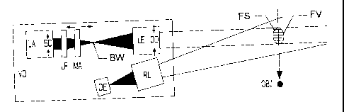
A velocity detector according to an embodiment of the present invention is
schematically illustrated in Figure 1. The velocity detector VD has a defined
field of
view FV and comprises a laser assembly LA producing a converging beam with an
initial diameter BD that passes through a mask assembly MA comprising, for
example,
a pattern of opaque lines deposited onto a glass substrate, as illustrated in
Figure 3. The
mask pattern modulates the laser beam which is then re-focussed by a lens
assembly LE
back to a parallel output beam with a beam diameter OD. This output beam will
project
the image of the mask throughout its length, such image being a pattern of
light and
dark "fringes". An object passing through the output beam will reflect light
from the
fringes FS in a series of pulses as it passes through each light fringe, the
pulses being at
a frequency determined by the object velocity and the fringe pattern. The
reflected
light is detected by an opto-electronic detector assembly DE having a
receiving lens RL
and capable of being directed and focussed onto the path of an object OBJ
passing
through the beam, the defined field of view FV being created by the
intersection of the
output beam and the acceptance volume of the receiving lens RL. The frequency
of the
detected pulses can thus be used to derive the velocity of the moving object,
i.e. the
velocity is given by frequency- velocity constant.
The laser assembly LA has a focussing means LF which allows the laser beam to
be
convergent at a point BW known as the "beam waist", the minimum diameter of
which
is a defined characteristic of the laser light at a given wavelength and known
beam
geometry. The mask assembly MA is mounted in a mask carrier which allows the
CA 02661560 2009-02-24
WO 2008/023187 PCT/GB2007/003229
6
mask to be rotated relative to the principal axis of the laser beam and moved
to occupy
any position between the laser output aperture and the beam waist.
Moving the mask carrier both in rotation and position allows the orientation
of the
fringes to change and also the number of fringes which will appear in the
output beam
to change. The lens assembly LE is focussed on its input side onto the surface
of the
mask assembly holding the defined pattern, and on its output side, creates a
collimated
output beam with diameter OD. By a combination of adjustments and selected
positions of the laser focussing means LF, the laser output aperture BD, the
mask
assembly MA and the lens assembly LE a defined pattern of light and dark
"fringes" FS
in a variety of orientations, size and scaling can be projected into the
output beam.
An object OBJ passing through the field of view FV will reflect laser light
from the
fringes FS back to the receiver lens RL. The physical surface characteristics
of the
object, and principally its roughness, will in part determine the amount of
modulated
light reflected. The ability of the instrument to readily change the fringe
parameters by
movement and rotation of the mask MA will allow a better match with a given
object,
and by so doing, will maximise the depth of modulation of the returned signal.
The receiver assembly comprising lens RL and detector DE may also be rotated
about a
fixed point in order to align the principal axis of lens RL with a point on
the laser beam
through which any object might pass, thereby maximising the returned signal
from the
object to detector DE. It will be appreciated by those skilled in the art that
other
detection schemes and arrangements may be employed. For example, an
arrangement
utilising a detector without the requirement for a receiving lens RL may be
employed in
further embodiments of the present invention.
This invention allows the generation of optical fringes within a measurement
volume in
a manner which does not rely on the precise manipulation of the crossing point
and
focussing of laser beams into a defined position, and also optionally allows
the
orientation of the fringes to be changed without having to rotate the entire
instrument.
Furthermore, the measurement volume length is not restricted to the crossing
point of
two laser beams, thereby allowing measurement of objects passing on a plane.
Finally,
CA 02661560 2011-03-15
7
the fringe spacing (and hence the fringe passing frequency) is not determined
by
interference effects, and can therefore be chosen to best suit the application
at hand.
This variability of fringe parameters will allow the use of velocimetry
techniques in a
very wide range of applications, with velocities ranging from quite slow
(mm/sec) to
very, very high (km/sec) using detector bandwidth figures in a more economic
range
than is possible with conventional LDV systems using interference fringe
generation.
For example, a measurement volume diameter of 5mm having 20 fringes will have
a
velocity constant of 4kHz/metre/sec. With a detector bandwidth of 10MHz, this
would
allow velocities of 2,500 metres/second to be measured, compared with 44
metres/sec
for the same detector in the conventional crossed beam velocimeter.
FIGURE 2 shows an example of the signal generated by an object passing through
the
measurement volume. The signal envelope is Gaussian, matching the intensity
profile
of the measurement volume, and illustrates a passing frequency of
approximately 130
kHz with a 100 line mask assembly. With a 5mm diameter mask, this would
indicate
an object velocity of 6.25 metres per second with a Doppler constant of 20.8
kHz per
metre per second.
When the mask assembly MA is printed with a regular pattern of parallel lines,
as
illustrated in Figure 3, the gaps between the lines can be considered to be a
series of
"slits". It is well known that light passing through a narrow slit creates a
diffraction
pattern, with an expanding wavefront centred on the slit and with a period
determined
by the wavelength of the light. When light passes through more than one
parallel slit
and those slits are adjacent (in relative terms), the wavefronts from each
slit interact
with each other, adding and subtracting, and in a manner which is determined
by the slit
spacing. This phenomenon creates light and dark "fringes" across the
wavefronts.
However, as this is exactly the effect required in the invention, the optical
components
and laser beam can be adjusted so as to ensure that any diffraction effects
are actually
added to the masking effect of the slit, and the two independent sets of
fringes
effectively superimpose, thereby enhancing the efficiency of the technique.
Alternately, the optical components and laser beam can be adjusted to
eliminate or
greatly reduce any diffraction effects, allowing the mask alone to generate
the projected
pattern. The use of laser light at a tightly defined wavelength and with a
high degree of
CA 02661560 2011-03-15
8
spatial and temporal coherence ensures that the quality of the fringe pattern
generated is
very high, both in geometric regularity and in light-to-dark contrast.
This method of producing fringes in a measurement volume can be implemented in
a
number of configurations, for example with either divergent or convergent
laser beams,
depending on the laser beam diameter and the diameter required for the final
measurement volume, or with a parallel laser beam, and with any configuration
of
lenses to produce the required fringes at a given working distance from the
instrument.
Additionally, the mask assembly MA may be printed with other patterns, such as
a
series of concentric circles, that produces light and dark `fringes',
depending upon the
desired application and measurements to be taken.