Note : Les descriptions sont présentées dans la langue officielle dans laquelle elles ont été soumises.
CA 02661712 2013-12-11
A. TITLE
STEERABLE MULTI-LINKED DEVICE HAVING
MULTIPLE WORKING PORTS
Inventors: Howie Choset, Brett Zubiate, Amir Degani
B.-E. NOT APPLICABLE
F. BACKGROUND
100021 This application discloses an invention that is related, generally and
in
various embodiments, to a steerable multi-linked device having multiple
working ports.
100031 There are many types of steerable multi-linked devices, and such
devices are
utilized in a number of applications. For some of the applications, it is
desirable to be able
to pass a plurality of devices (e.g., a camera, a fiber optic, a surgical
tool, etc.) from a first
end of a steerable multi-linked device to a second end of the steerable multi-
linked device.
Although some steerable multi-linked devices define a center passage which
extends from
one end of the device to the other end of the device, such center passages are
generally
configured to allow only one device to pass therethrough.
CA 02661712 2009-02-17
WO 2008/022114
PCT/US2007/075878
G. SUMMARY
[0004] In one general respect. this application discloses a steerable multi-
linked
device. According to various embodiments, the device includes a first multi-
linked
mechanism and a second multi-linked mechanism. The first multi-linked
mechanism defines
a first plurality of grooves. The second multi-linked mechanism defines a
second plurality
of grooves. The first and second pluralities of grooves cooperate to define at
least two
working ports along a length of the device. At least one of the first and
second mechanisms
are steerable.
H. DESCRIPTION OF DRAWINGS
[0005] Various embodiments of the invention are described herein by way of
example in conjunction with the following figures.
[0006] FIGS. IA and I B illustrate various embodiments of a steerable multi-
linked
device;
[0007] FIG. 2 illustrates various embodiments of a first mechanism of the
device of
FIG. I;
[0008] FIGS. 3A-3C illustrate various embodiments of a first link of the first
mechanism of FIG. 2;
[0009] FIGS. 4A-4C illustrate various embodiments of an intermediate link of
the
first mechanism of FIG. 2;
100101 FIGS. 5A-5C illustrate various embodiments of a second link of the
first
mechanism of FIG. 2;
[0011] FIG. 6 illustrates various embodiments of a second mechanism of the
device
of FIG. 1;
-2-
CA 02661712 2009-02-17
WO 2008/022114
PCT/US2007/075878
100121 FIGS. 7A-7C illustrate various embodiments of a first link of the
second
mechanism of FIG. 6;
[0013] FIGS. 8A-8C illustrate various embodiments of an intermediate link of
the
second mechanism of FIG. 6;
[0014] FIGS. 9A-9D illustrate various embodiments of a second link of the
second
mechanism of FIG. 6;
[0015] FIG. 10 illustrates various embodiments of a motion sequence of the
device
of FIG. 1; and
100161 FIG. 11 illustrates various embodiments of a steerable multi-linked
device
traversing a path having tight curvatures.
I. DETAILED DESCRIPTION
[0017] It is to be understood that at least some of the figures and
descriptions of the
invention have been simplified to focus on elements that are relevant for a
clear
understanding of the invention, while eliminating, for purposes of clarity,
other elements that
those of ordinary skill in the art will appreciate may also comprise a portion
of the invention.
However, because such elements are well known in the art, and because they do
not
necessarily facilitate a better understanding of the invention, a description
of such elements
is not provided herein.
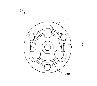
[0018] Figures IA and 113 illustrate various embodiments of a steerable multi-
linked
device 10. As used herein, the term "steerable" means that an end of the
device 10 can be
guided in a number of directions (e.g., up, down, left, right, etc.) relative
to another portion
of the device 10. Various embodiments of the device 10 may be utilized for
medical
procedures (e.g., minimally invasive procedures), for surveillance
applications, for
inspection applications, for search and rescue applications, etc. For purposes
of clarity only,
-3-
CA 02661712 2009-02-17
WO 2008/022114
PCT/US2007/075878
the utility of the device 10 will be described hereinbelow in the context of
its applicability to
medical procedures. However, a person skilled in the art will appreciate that
the device 10
can be utilized in a variety of different applications.
100191 The device 10 comprises a first mechanism 12 and a second mechanism 14.
According to various embodiments, the second mechanism 14 is structured and
arranged to
receive and surround the first mechanism 12 as shown in Figure 1B. For such
embodiments,
the first mechanism 12 may be considered the inner mechanism or the core
mechanism, and
the second mechanism 14 may be considered the outer mechanism or the sleeve
mechanism.
According to other embodiments, the first and second mechanisms 12, 14 may be
structured
and arranged to have a relationship other than a concentric relationship. For
example, one
skilled in the art will appreciate that, according to various embodiments, the
first and second
mechanisms 12, 14 may be structured and arranged to operate in a side-by-side
arrangement,
where the first mechanism 12 operates adjacent to the second mechanism 14. As
described
in more detail hereinbelow, the first mechanism 12 may operate in either a
rigid mode or a
limp mode, the second mechanism 14 may operate in either a rigid mode or a
limp mode,
and the first and second mechanisms 12, 14 may operate independent of one
another.
100201 As used herein, the term "limp" means highly flexible. Thus, when
either the
first or second mechanism 12, 14 is in the limp mode, the limp mechanism
either assumes
the shape of its surroundings or can be reshaped. It should be noted that the
term "limp" as
used herein does not denote a structure that passively assumes a particular
configuration
dependent upon gravity and the shape of its environment. Rather, when either
the first or
second mechanism 12, 14 is in the limp mode, the limp mechanism is capable of
assuming
positions and configurations that are desired by an operator of the device 10,
and are
therefore articulated and controlled rather than flaccid and passive.
-4-
CA 02661712 2009-02-17
WO 2008/022114
PCT/US2007/075878
[0021] Both the first mechanism 12 and the second mechanism 14 may be
steerable
mechanisms. Accordingly, it will be appreciated that the device 10 may be
utilized to
navigate a luminal space as well as any three-dimensional path within an
intracavity space.
The device 10 may also comprise a first cable 16, a second cable 18, a third
cable 20, and a
fourth cable 22. The first, second and third cables 16, 18, 20 may be
considered steering
cables, and the fourth cable 22 may be considered a tensioning cable.
100221 Figure 2 illustrates various embodiments of the first mechanism 12 of
the
device 10. The first mechanism 12 is a multi-linked mechanism and includes a
first end 24
and a second end 26. The first end 24 may be considered the proximal end and
the second
end 26 may be considered the distal end. The first mechanism 12 comprises a
first link 28, a
second link 30, and any number of intermediate links 32 between the first and
second links
28, 30. The first link 28 may be considered the proximal link, and the second
link 30 may be
considered the distal link.
[0023] Figures 3A-3C illustrate various embodiments of the first link 28
(inner
proximal link) of the first mechanism 12. The first link 28 includes a first
end 34 and a
second end 36, and defines a longitudinal axis 38 that passes through the
center of the first
end 34 and the center of the second end 36 as shown in Figure 3B. The first
link 28 may be
fabricated from any suitable material. According to various embodiments, the
first link 28 is
fabricated from a fiber reinforced material such as, for example, 610/FR4
Garolitet. The
first link 28 has a generally cylindrical shaped exterior and is described in
more detail
hereinbelow.
100241 The first link 28 comprises a first portion 40 and a second portion 42.
The
first portion 40 may be considered the proximal portion and the second portion
42 may be
considered the distal portion. The first portion 40 may be fabricated integral
with the second
portion 42. The first portion 40 has a cylindrical shaped exterior, and
extends from the first
-5-
CA 02661712 2009-02-17
WO 2008/022114
PCT/US2007/075878
end 34 of the first link 28 toward the second end 36 of the first link 28.
According to
various embodiments, the diameter of the first portion 40 is on the order of
approximately
6.35 millimeters.
100251 The second portion 42 has a generally cylindrically shaped exterior.
The
second portion 42 has a cylindrically shaped exterior where it contacts the
first portion 40,
and tapers toward the second end 36 of the first link 28. The second portion
42 may be
shaped in the form of a generally segmented hemisphere at the second end 36 of
the first link
28. According to various embodiments, the diameter of the second portion 42 is
on the order
of approximately 4.75 millimeters where it contacts the first portion 40.
[0026] The second portion 42 comprises a first surface 44. The first surface
44 may
be considered the outer surface of the second portion 41 The second portion 42
defines a
first groove 46 parallel to the longitudinal axis 38 along the first surface
44, a second groove
48 parallel to the longitudinal axis 38 along the first surface 44, and a
third groove 50
parallel to the longitudinal axis 38 along the first surface 44. Each of the
first, second and
third grooves 46, 48, 50 extend along the first surface 44 toward the second
end 36 of the
first link 28. The first, second and third grooves 46, 48, 50 may be semi-
tubular shaped and
may be evenly spaced about the first surface 44 of the second portion 42 of
the first link 28
as shown in Figure 3C. According to various embodiments. the first, second,
and third
grooves 46, 48, 50 may be configured in the shape of a segmented cylinder. The
size of each
of the grooves 46, 48, SO may identical to one another or may be different
from one another.
For example, according to various embodiments, the first and second grooves
46, 48 are
configured as segments of a cylinder having a diameter on the order of
approximately 1.25
millimeters, and the third groove 50 is configured as a segment of a cylinder
having a
diameter on the order of approximately 2.50 millimeters. The length of the
first link 28 may
-6-
CA 02661712 2009-02-17
WO 2008/022114
PCT/US2007/075878
be on the order of approximately 65 millimeters. However, one skilled in the
art will
appreciate that the length of the first link 28 can vary based on the
application.
[00271 The first link 28 also defines a passage 52 extending from the first
end 34 to
the second end 36 along the longitudinal axis 38 as shown in Figure 3B. The
passage 52 is
of a size sufficient to allow the fourth cable 22 to pass therethrough.
According to various
embodiments, the passage 52 is generally configured as a complex shape that
comprises a
combination of a first cylinder 54 that extends from the first end 34 toward
the second end
36, and a second cylinder 56 that extends from the first cylinder 54 toward
the second end
36. The diameter of the first cylinder 54 is larger than the diameter of the
second cylinder
56. For example, according to various embodiments, the first cylinder 54 has a
diameter on
the order of approximately 3.20 millimeters and the second cylinder 56 has a
diameter on the
order of approximately 1.50 millimeters.
100281 Figures 4A-4C illustrate various embodiments of one of the intermediate
links 32 (inner intermediate link) of the first mechanism 12. The intermediate
link 32 is
representative of the other intermediate links 32. The intermediate link 32
includes a first
end 58 and a second end 60, and defines a longitudinal axis 62 that passes
through the center
of the first end 58 and the center of the second end 60 as shown in Figure 4B.
The
intermediate link 32 may be fabricated from any suitable material. According
to various
embodiments, the intermediate link 32 is fabricated from a fiber reinforced
material such as,
for example, G10/FR4 Garolite10. The intermediate link 32 has a generally
bullet-shaped
exterior and is described in more detail hereinbelow.
100291 The intermediate link 32 comprises a first portion 64 and a second
portion 66.
The first portion 64 may be considered the proximal portion and the second
portion 66 may
be considered the distal portion. The first portion 64 may be fabricated
integral with the
second portion 66. The first portion 64 has a generally cylindrical shaped
exterior, and
-7-
CA 02661712 2009-02-17
WO 2008/022114
PCT/US2007/075878
extends from the first end 58 of the intermediate link 32 toward the second
end 60 of the
intermediate link 32. According to various embodiments, the second portion 66
has a
generally cylindrically shaped exterior where it contacts the first portion
64, and tapers
toward the second end 60 of the intermediate link 32. The exterior of the
second portion 66
is configured in the form of a generally segmented hemisphere_ According to
various
embodiments, the diameter of the intermediate link 32 is on the order of
approximately 4.75
millimeters at the first end 58 thereof. The length of the intermediate link
32 may be on the
order of approximately 5.85 millimeters. However, one skilled in the art will
appreciate that
the length of the intermediate link 32 can vary based on the application.
[0030] The intermediate link 32 also comprises a first surface 68 that extends
from
the first end 58 of the intermediate link 32 to the second end 60 of the
intermediate link 32.
The first surface 68 may be considered the outer surface of the intermediate
link 32. The
intermediate link 32 also defines a first groove 70 parallel to the
longitudinal axis 62 along
the first surface 68, a second groove 72 parallel to the longitudinal axis 62
along the first
surface 68, and a third groove 74 parallel to the longitudinal axis 62 along
the first surface
68. Each of the first, second and third grooves 70, 72, 74 extend along the
first surface 68
from the first end 58 of the intermediate link 32 toward the second end 60 of
the
intermediate link 32. The first, second and third grooves 70, 72, 74 may be
semi-tubular
shaped and may be evenly spaced about the first surface 68 of the intermediate
link 32 as
shown in Figure 4C. According to various embodiments, the first, second, and
third grooves
70, 72, 74 may be configured in the shape of a segmented cylinder. The size of
each of the
grooves 70, 72, 74 may identical to one another or may be different from one
another. For
example, according to various embodiments, the first and second grooves 70, 72
are
configured as segments of a cylinder having a diameter on the order of
approximately 1.75
millimeters at the first end 58 of the intermediate link 32, and the third
groove 74 is
-8-
CA 02661712 2009-02-17
WO 2008/022114
PCT/US2007/075878
configured as a segment of a cylinder having a diameter on the order of
approximately 2,50
millimeters at the first end 58 of the intermediate link 32. The first, second
and third
grooves 70, 72. 74 are each configured to receive and partially surround any
of a variety of
tools or instruments (e.g., ablation tools) which may pass from the first end
24 of the multi-
linked device 10 to the second end 26 of the multi-linked device 10.
100311 The intermediate link 32 also defines a passage 76 extending from the
first
end 58 to the second end 60 along the longitudinal axis 62 as shown in Figure
4B. The
passage 76 is of a size sufficient to allow the fourth cable 22 to pass
therethrough.
According to various embodiments, the passage 76 is generally configured as a
complex
shape that comprises a combination of a first segmented hemisphere 78 that
extends from the
first end 58 toward the second end 60, a second segmented hemisphere 80 that
extends from
the first segmented hemisphere 78 toward the second end 60, a cylinder 82 that
extends from
the second segmented hemisphere 80 toward the second end 60, and a third
segmented
hemisphere 84 that extends from the cylinder 82 to the second end 60 of the
intermediate
link 32. According to various embodiments, the first segmented hemisphere 78
represents a
portion of a sphere having a diameter on the order of approximately 435
millimeters, the
second segmented hemisphere 80 represents a portion of a sphere having a
diameter on the
order of approximately 2.25 millimeters, the cylinder 82 has a diameter on the
order of
approximately 1.0 millimeter, and the third segmented hemisphere 84 represents
a portion of
a sphere having a diameter on the order of approximately 2.25 millimeters.
100321 The first segmented hemisphere 78 of the passage 76 is configured to
receive
the second end 36 of the first link 28 when the first link 28 is coupled to
the intermediate
link 32. Similarly, for a given intermediate link 32, the first segmented
hemisphere 78 of the
passage 76 is configured to receive the second end 60 of another intermediate
link 32 when
the other intermediate link 32 is coupled to the given intermediate link 32.
The third
-9-
CA 02661712 2009-02-17
WO 2008/022114
PCT/US2007/075878
segmented hemisphere 84 may serve to reduce the pinching or binding of the
fourth cable 22
when one intermediate link 32 moves relative to an adjacent intermediate link
32 coupled
thereto. Similarly, when the second link 30 is coupled to a given intermediate
link 32, the
third segmented hemisphere 84 may serve to reduce the pinching or binding of
the fourth
cable 22 when the second link 30 moves relative to the given intermediate link
32.
100331 With the above described structure, the first link 28 may be coupled to
the
intermediate link 32 by seating the second end 36 of the first link 28 in the
first segmented
hemisphere 78 of the passage 76 of the intermediate link 32. As the convex
configuration of
the second end 36 of the first link 28 generally corresponds with the concave
configuration
of the first segmented hemisphere 78 of the passage 76 of the intermediate
link 32, the first
link 28 may be coupled to the intermediate link 32 such that the longitudinal
axis 38 and the
first, second and third grooves 46, 48, 50 of the first link 28 are
respectively aligned with the
longitudinal axis 62 and the first, second and third grooves 70, 72, 74 of the
intermediate
link 32. The intermediate link 32 may be moved relative to the first link 28
such that the
longitudinal axis 62 of the intermediate link 32 is not aligned with the
longitudinal axis 38 of
the first link 28. According to various embodiments, the configuration of the
first link 28
and the intermediate link 32 allows for the intermediate link 32 to be moved
relative to the
first link 28 coupled thereto such that the longitudinal axis 38 of the first
link 28 and the
longitudinal axis 62 of the intermediate link 32 are up to approximately 25
out of alignment
with one another. Similarly, one intermediate link 32 may be coupled to
another
intermediate link 32, and so on, by seating the second end 60 of one
intermediate link 32 in
the first segmented hemisphere 78 of the passage 76 of another intermediate
link 32. As the
convex configuration of the second end 60 of the intermediate link 32
generally corresponds
with the concave configuration of the first segmented hemisphere 78 of the
passage 76 of the
intermediate link 32, the intermediate links 32 may be coupled such that the
respective
-10-
CA 02661712 2009-02-17
WO 2008/022114
PCT/US2007/075878
longitudinal axes 62 and the respective first, second and third grooves 46,
48, 50 of the
intermediate links 32 are aligned. The coupled intermediate links 32 may be
moved relative
to one another such that the respective longitudinal axes 62 of the coupled
intermediate links
32 are not aligned. According to various embodiments, the configuration of the
coupled
intermediate links 32 allows for one intermediate link 32 to be moved relative
to an adjacent
intermediate link 32 coupled thereto such that the respective longitudinal
axes 62 are up to
approximately 25 out of alignment with one another.
100341 Figures 5A-5C illustrate various embodiments of the second link 30
(inner
distal link) of the first mechanism 12. The second link 30 includes a first
end 86 and a
second end 88, and defines a longitudinal axis 90 that passes through the
center of the first
end 86 and the center of the second end 88 as shown in Figure 5B. The second
link 30 may
be fabricated from any suitable material. According to various embodiments,
the second
link 30 is fabricated from a thermoplastic material such as, for example,
Delrint.
100351 The second link 30 comprises a first portion 92 and a second portion
94. The
first portion 92 may be considered the proximal portion and the second portion
94 may be
considered the distal portion. The first portion 92 may be fabricated integral
with the second
portion 94. The first portion 92 has a generally cylindrical shaped exterior,
and extends from
the first end 86 of the second link 30 toward the second end 88 of the second
link 30,
According to various embodiments, the second portion 94 has a generally
cylindrically
shaped exterior where it contacts the first portion 92, and tapers toward the
second end 88 of
the second link 30. The exterior of the second portion 64 is configured in the
form of a
generally segmented cone. According to various embodiments, the diameter of
the second
link 30 is on the order of approximately 4.75 millimeters at the first end 86
thereof, and the
taper of the second portion 94 is at an angle of approximately 30 relative to
the exterior of
the first portion 92. The length of the second link 30 may be on the order of
approximately
-11-
CA 02661712 2009-02-17
WO 2008/022114
PCT/US2007/075878
5.90 millimeters. However, one skilled in the art will appreciate that the
length of the
second link 30 can vary based on the application.
[0036] The second link 30 also comprises a first surface 96 that extends from
the
first end 86 of the second link 30 to the second end 88 of the second link 30.
The first
surface 96 may he considered the outer surface of the second link 30. The
second link 30
also defines a first groove 98 parallel to the longitudinal axis 90 along the
first surface 96, a
second groove 100 parallel to the longitudinal axis 90 along the first surface
96, and a third
groove 102 parallel to the longitudinal axis 90 along the first surface 96.
Each of the first,
second and third grooves 98, 100, 102 extend along the first surface 96 from
the first end 86
of the second link 30 toward the second end 88 of the second link 30. The
first, second and
third grooves 98, 100, 102 may be semi-tubular shaped and may be evenly spaced
about the
first surface 96 of the second link 30 as shown in Figure 5C. According to
various
embodiments, the first, second, and third grooves 98, 100, 102 may be
configured in the
shape of a segmented cylinder. The size of each of the grooves 98, 100, 102
may identical to
one another or may be different from one another. For example, according to
various
embodiments, the first and second grooves 98, 100 are configured as segments
of a cylinder
having a diameter on the order of approximately 1.25 millimeters at the first
end 86 of the
second link 30, and the third groove 102 is configured as a segment of a
cylinder having a
diameter on the order of approximately 2.50 millimeters at the first end 86 of
the second link
30. The first, second and third grooves 98, 100, 102 are each configured to
receive and
partially surround any of a variety of tools or instruments (e.g., ablation
tools) which may
pass from the first end 24 of the multi-linked device 10 to the second end 26
of the multi-
linked device 10.
[0037] The second link 30 also defines a passage 104 extending from the first
end 86
to the second end 88 along the longitudinal axis 90 as shown in Figure 58. The
passage 104
-12-
CA 02661712 2009-02-17
WO 2008/022114
PCT/US2007/075878
is of a size sufficient to allow the fourth cable 22 to pass therethrough.
According to various
embodiments, the passage 104 is generally configured as a complex shape that
comprises a
combination of a first segmented hemisphere 106 that extends from the first
end 86 toward
the second end 88, a second segmented hemisphere 108 that extends from the
first
segmented hemisphere 106 toward the second end 88, and a cylinder 110 that
extends from
the second segmented hemisphere 108 to the second end 88 of the second link
30.
According to various embodiments, the first segmented hemisphere 106
represents a portion
of a sphere having a diameter on the order of approximately 4.75 millimeters,
the second
segmented hemisphere 108 represents a portion of a sphere having a diameter on
the order of
approximately 2.50 millimeters, and the cylinder 110 has a diameter on the
order of
approximately 1.0 millimeter. The first segmented hemisphere 106 of the
passage 104 is
configured to receive the second end 60 of an intermediate link 32 when the
intermediate
link 32 is coupled to the second link 30.
100381 With the above described structure, an intermediate link 32 may be
coupled to
the second link 30 by seating the second end 60 of the intermediate link 32 in
the first
segmented hemisphere 106 of the passage 104 of the second link 30. As the
convex
configuration of the second end 60 of the intermediate link 32 generally
corresponds with
the concave configuration of the first segmented hemisphere 106 of the passage
104 of the
second link 30, the intermediate link 32 may be coupled to the second link 30
such that the
longitudinal axis 62 and the first, second and third grooves 70, 72, 74 of the
intermediate
link 32 are respectively aligned with the longitudinal axis 90 and the first,
second and third
grooves 98, 100, 102 of the second link 30. The second link 30 may be moved
relative to
the intermediate link 32 coupled thereto such that the respective longitudinal
axes 62, 90 are
not aligned. According to various embodiments, the configuration of the second
link 30
allows for an intermediate link 32 coupled thereto to be moved relative to the
second link 30
-13-
CA 02661712 2009-02-17
WO 2008/022114
PCT/US2007/075878
such that the respective longitudinal axes 62, 90 are up to approximately 250
out of
alignment with one another.
10039] Figure 6 illustrates various embodiments of the second mechanism 14 of
the
device 10. The second mechanism 14 is a multi-linked mechanism and includes a
first end
120 and a second end 122. The first end 120 may be considered the proximal end
and the
second end 122 may be considered the distal end. The second mechanism 14
comprises a
first link 124, a second link 126, and any number of intermediate links 128
between the first
and second links 124, 126. The first link 124 may be considered the proximal
link, and the
second link 126 may be considered the distal link.
10040] Figures 7A-7C illustrate various embodiments of the first link 124
(outer
proximal link) of the second mechanism 14. The first link 124 includes a first
end 130 and a
second end 132, and defines a longitudinal axis 134 that passes through the
center of the first
end 130 and the center of the second end 132 as shown in Figure 7B. The first
link 124 may
be fabricated from any suitable material. According to various embodiments,
the first link
124 is fabricated from a stainless steel material such as, for example, 316
stainless steel. The
first link 124 has a generally buIlet-shaped exterior and is described in more
detail
hereinbelow.
100411 The first link 124 comprises a first portion 136 and a second portion
138.
The first portion 136 may be considered the proximal portion and the second
portion 138
may be considered the distal portion. The first portion 136 may be fabricated
integral with
the second portion 138. The first portion 136 has a cylindrical shaped
exterior, and extends
from the first end 130 of the first link 124 toward the second end 132 of the
first link 124.
According to various embodiments, the diameter of the first portion 136 is on
the order of
approximately 12.70 millimeters.
-14-
CA 02661712 2009-02-17
WO 2008/022114
PCT/US2007/075878
100421 The second portion 138 has a generally cylindrically shaped exterior.
The
second portion 138 has a cylindrically shaped exterior where it contacts the
first portion 136,
and tapers toward the second end 132 of the first link 124. The second portion
138 may be
shaped in the form of a generally segmented hemisphere at the second end 132
of the first
link 124. According to various embodiments, the diameter of the second portion
138 is on
the order of approximately 9.50 millimeters where it contacts the first
portion 136.
100431 The second portion 138 comprises a first surface 140. The first surface
140
may be considered the outer surface of the second portion 138. The second
portion 138
defines a first groove 142 along the first surface 140, a second groove 144
along the first
surface 140, and a third groove 146 along the first surface 140. Each of the
first, second and
third grooves 142, 144, 146 are oblique relative to the longitudinal axis 134
and extend
along the first surface 140 toward the second end 132 of the first link 124.
According to
various embodiments, each of the grooves 142, 144, 146 are oriented at an
angle on the order
of approximately 15 relative to the longitudinal axis 134. As shown in Figure
7C, the first,
second and third grooves 142, 144, 146 may be evenly spaced about the first
surface 140 of
the first link 124. According to various embodiments, the first, second, and
third grooves
142, 144, 146 may be configured in the shape of a segmented cylinder. The size
of each of
the grooves 142, 144, 146 may identical to one another or may be different
from one
another. For example, according to various embodiments, each of the grooves
142, 144, 146
are configured as segments of respective cylinders having diameters on the
order of
approximately 3.0 millimeters. The first, second and third grooves 142, 144,
146 are each
configured to facilitate the introduction various tools or instruments (e.g.,
ablation tools) into
the multi-linked device 10. The length of the first link 124 may be on the
order of
approximately 18.5 millimeters. However, one skilled in the art will
appreciate that the
length of the first link 124 can vary based on the application.
-15-
CA 02661712 2009-02-17
WO 2008/022114
PCT/US2007/075878
100441 The first link 124 also defines a passage 148 extending from the first
end 130
to the second end 132 along the longitudinal axis 134 as shown in Figure 713.
The passage
148 is of a size sufficient to allow the first mechanism 12 to pass
therethrough. According to
various embodiments, the passage 148 is generally configured as a complex
shape that
comprises a combination of a segmented cone 150 that extends from the first
end 130 toward
the second end 132, and a cylinder 152 that extends from the segmented cone
150 to the
second end 132 of the first link 124. According to various embodiments, the
segmented
cone 150 has a diameter on the order of approximately 7.0 millimeters at the
first end 130 of
the first link 124, and is tapered at an angle on the order of approximately
450 relative to the
longitudinal axis 134. The cylinder 152 has a diameter on the order of
approximately 5.50
millimeters.
[0045] The first link 124 also defines a first through-hole 154, a second
through-hole
156, and a third through-hole 158. (See Figure 7C). The first through-hole 154
is
substantially parallel to the longitudinal axis 134, extends from the first
portion 136 toward
the second end 132, and is positioned between the passage 148 and the first
surface 140.
The second through-hole 156 is substantially parallel to the longitudinal axis
134, extends
from the first portion 136 to the second end 132, and is positioned between
the passage 148
and the first surface 140. The third through-hole 158 is substantially
parallel to the
longitudinal axis 134, extends from the first portion 136 to the second end
132, and is
positioned between the passage 148 and the first surface 140. The first,
second and third
through-holes 154, 156, 158 are generally cylindrically shaped. According to
various
embodiments, the through-holes 154, 156, 158 are evenly spaced from one
another as shown
in Figure 7C. The size of each of the through-holes 154, 156, 158 may be
identical to one
another or may be different from one another. For example, according to
various
embodiments, the respective diameters associated with the through-holes 154,
156, I58 may
-16-
CA 02661712 2009-02-17
WO 2008/022114
PCT/US2007/075878
each be on the order of approximately 1.20 millimeters. The first through-hole
154 is
configured to receive and surround the first cable 16. The second through-hole
156 is
configured to receive and surround the second cable 18. The third through-hole
158 is
configured to receive and surround the third cable 20. The first, second and
third through-
holes 154, 156, 158 may serve as guidepaths for movement of the first, second
and third
cables 16, 18, 20.
100461 Figures 8A-8C illustrate various embodiments of one of the intermediate
links 128 (outer intermediate link) of the second mechanism 14. The
intermediate link 128
is representative of the other intermediate links 128. The intermediate link
128 includes a
first end 160 and a second end 162, and defines a longitudinal axis 164 that
passes through
the center of the first end 160 and the center of the second end 162 as shown
in Figure 8B.
The intermediate link 128 may be fabricated from any suitable material.
According to
various embodiments, the intermediate link 128 is fabricated from a polymer
thermosplastic
material such as, for example, polysulfone. The intermediate link 128 has a
generally bullet-
shaped exterior and is described in more detail hereinbelow.
109471 The intermediate link 128 comprises a first portion 166 and a second
portion
168. The first portion 166 may be considered the proximal portion and the
second portion
168 may be considered the distal portion. The first portion 166 may be
fabricated integral
with the second portion 168. The first portion 166 has a generally cylindrical
shaped
exterior, and extends from the first end 160 of the intermediate link 128
toward the second
end 162 of the intermediate link 128. According to various embodiments, the
second portion
168 has a generally cylindrically shaped exterior where it contacts the first
portion 166, and
tapers toward the second end 162 of the intermediate link 128. The exterior of
the second
portion 168 is configured in the form of a generally segmented hemisphere.
According to
various embodiments, the diameter of the intermediate link 128 is on the order
of
-17-
CA 02661712 2009-02-17
WO 2008/022114
PCT/US2007/075878
approximately 9.65 millimeters at the first end 160 thereof. The length of the
intermediate
link 128 may be on the order of approximately 8.40 millimeters. However, one
skilled in the
art will appreciate that the length of the intermediate link 128 can vary
based on the
application.
100481 The intermediate link 128 also comprises a first surface 170 that
extends from
the first end 160 of the intermediate link 128 to the second end 162 of the
intermediate link
128, and a second surface 170 that extends from the first end 160 of the
intermediate link
128 to the second end 162 of the intermediate link 128. The first surface 170
may be
considered the outer surface of the intermediate link 128, and the second
surface 172 may be
considered the inner surface of the intermediate link 128. The intermediate
link 32 also
defines a first groove 174 substantially parallel to the longitudinal axis 164
along the second
surface 172, a second groove 176 substantially parallel to the longitudinal
axis 164 along the
second surface 172, and a third groove 178 substantially parallel to the
longitudinal axis 164
along the second surface 172. Each of the first, second and third grooves 174,
176, 178
extend along the second surface 172 toward the second end 162 of the
intermediate link 128.
The first, second and third grooves 174, 176, 178 may be semi-tubular shaped
and may be
evenly spaced about the second surface 172 of the intermediate link 128 as
shown in Figure
8C. According to various embodiments, the first, second, and third grooves
174, 176, 178
may be configured in the shape of a segmented cylinder. The size of each of
the grooves
174, 176, 178 may identical to one another or may be different from one
another. For
example, according to various embodiments, the first and second grooves 174,
176 are
configured as segments of cylinders having diameters on the order of
approximately 1.75
millimeters at the first end 160 of the intermediate link 128, and the third
groove 178 is
configured as a segment of a cylinder having a diameter on the order of
approximately 150
millimeters at the first end 160 of the intermediate link 128. The first,
second and third
-18-
CA 02661712 2009-02-17
WO 2008/022114
PCT/US2007/075878
grooves 174, 176, 178 are each configured to receive and partially surround
any of a variety
of tools or instruments (e.g., ablation tools) which may pass from the first
end 24 of the
multi-linked device 10 to the second end 26 of the multi-linked device 10.
100491 The intermediate link 128 also defines a passage 180 extending from the
first
end 160 to the second end 162 along the longitudinal axis 164 as shown in
Figure 8B. The
passage 180 is of a size sufficient to allow the first mechanism 12 to pass
therethrough.
According to various embodiments, the passage 180 is generally configured as a
complex
shape that comprises a combination of a segmented hemisphere 182 that extends
from the
first end 160 toward the second end 162, a first segmented cone 184 that
extends from the
segmented hemisphere 182 toward the second end 162, a cylinder 186 that
extends from the
first segmented cone 184 toward the second end 162, and a second segmented
cone 188 that
extends from the cylinder 186 to the second end 162 of the intermediate link
128. According
to various embodiments, the segmented hemisphere 182 represents a portion of a
sphere
having a diameter on the order of approximately 9.65 millimeters, the first
segmented cone
184 is tapered at an angle on the order of approximately 15 relative to the
longitudinal axis
164, the cylinder 186 has a diameter on the order of approximately 5.50
millimeters, and the
second segmented cone 188 is tapered at an angle on the order of approximately
15 relative
to the longitudinal axis 164. The segmented hemisphere 182 of the passage 180
is
configured to receive the second end 132 of the first link 124 when the first
link 124 is
coupled to the intermediate link 128. Similarly, for a given intermediate link
128, the
segmented hemisphere 182 of the passage 180 is configured to receive the
second end 162 of
another intermediate link 128 when the other intermediate link 128 is coupled
to the given
intermediate link 128.
100501 The intermediate link 128 also defines a first through-hole 190, a
second
through-hole 192, and a third through-hole 194. (See Figure 8C). The first
through-hole
-19-
CA 02661712 2009-02-17
WO 2008/022114
PCT/US2007/075878
190 is substantially parallel to the longitudinal axis 164, extends from the
first portion 166
toward the second end 162, and is positioned between the passage 180 and the
first surface
170. The second through-hole 192 is substantially parallel to the longitudinal
axis 164,
extends from the first portion 166 to the second end 162, and is positioned
between the
passage 180 and the first surface 170. The third through-hole 194 is
substantially parallel to
the longitudinal axis 164, extends from the first portion 166 to the second
end 162, and is
positioned between the passage 180 and the first surface 170. The first,
second and third
through-holes 190, 192, 194 are generally cylindrically shaped. According to
various
embodiments, the through-holes 190, 192, 194 are evenly spaced from one
another. The size
of each of the through-holes 190, 192, 194 may be identical to one another or
may be
different from one another. For example, according to various embodiments, the
respective
diameters associated with the through-holes 190, 192, 194 may each be on the
order of
approximately 1.25 millimeters. The first through-hole 190 is configured to
receive and
surround the first cable 16. The second through-hole 192 is configured to
receive and
surround the second cable 18. The third through-hole 194 is configured to
receive and
surround the third cable 20. The first, second and third through-holes 190,
192, 194 may
serve as guidepaths for movement of the first, second and third cables 16, 18,
20.
100511 As shown in Figure 8C, the intermediate link 128 also defines first,
second
and third indents 196, 198, 200 at the second end 162 thereof resulting, in
part, from the
combination of the taper associated with the second portion 168 and the
configuration and
orientation of the first, second, and third grooves 174, 176, 178. The first,
second and third
indents 196, 198, 200 may be evenly spaced about the second end 162 of the
intermediate
link 128 as shown in Figure 8C. The first, second and third indents 196, 198,
200 may serve
to reduce the pinching or binding of various tools or instruments (e.g.,
ablation tools) when
-20-
CA 02661712 2009-02-17
WO 2008/022114
PCT/US2007/075878
one intermediate link 128 of the second mechanism 14 is moved relative to
another
intermediate link 128 coupled thereto.
10052] The intermediate link 128 also defines fourth, fifth and sixth indents
202,
204, 206 at the second end 162 thereof resulting from the combination of the
taper
associated with the second portion 168 and the configuration and orientation
of the first,
second, and third through-holes 190, 192, 194. The fourth, fifth and sixth
indents 202, 204,
206 may be evenly spaced about the second end 162 of the intermediate link
128, and may
be evenly spaced from the first, second and third indents 196, 198, 200 as
shown in Figure
8C. The fourth, fifth and sixth indents 202, 204, 206 may serve to reduce the
pinching or
binding of the first, second and third cables 16, 18, 20 when one intermediate
link 128 of the
second mechanism 14 is moved relative to another intermediate link 128 coupled
thereto.
[00531 According to various embodiments, an intermediate link 128 may also
define
an opening (not shown) that extends from the second surface 172 or from one of
the grooves
174, 176, 178 to the first surface 170 of the intermediate link 128. The
intermediate link 128
may have any number of such openings, and any number of the intermediate links
128 may
have such openings. The opening may be utilized as an exit point for a tool or
instrument
which may pass from the first end 24 of the multi-linked device 10 toward the
second end 26
of the multi-linked device 10. For such embodiments, the respective
intermediate link 128
may be positioned proximate the second link 126 of the second mechanism 14.
The opening
may be oriented at any angle relative to the longitudinal axis 134 of the
intermediate link
128. When the first mechanism 12 is removed from the second mechanism 14, and
a
relatively large tool or instrument is advanced from the first end 120 of the
second
mechanism 14 to the second end 122 of the second mechanism 14, sufficient room
may not
exist for a second tool or instrument (e.g., fiber optic cable) to pass
through the second end
-2 I -
CA 02661712 2009-02-17
WO 2008/022114
PCT/US2007/075878
122 of the second mechanism 14. For such instances, the second tool or
instrument may exit
through an opening of one of the intermediate links 128.
100541 With the above described structure, the first link 124 may be coupled
to the
intermediate link 128 by seating the second end 132 of the first link 124 in
the segmented
hemisphere 182 of the passage 180 of the intermediate link 128. As the convex
configuration of the second end 132 of the first link 124 generally
corresponds with the
concave configuration of the segmented hemisphere 182 of the passage 180 of
the
intermediate link 128, the first link 124 may be coupled to the intermediate
link 128 such
that the longitudinal axis 134, the first, second and third grooves 142, 144,
146, and the first,
second and third through-holes 154, 156, 158 of the first link 124 are
respectively aligned
with the longitudinal axis 164, the first, second and third grooves 174, 176,
178, and the
first, second and third through-holes 190, 192, 194 of the intermediate link
128. The
intermediate link 128 may be moved relative to the first link 124 such that
the longitudinal
axis 164 of the intermediate link 128 is not aligned with the longitudinal
axis 134 of the first
link 124. According to various embodiments, the configuration of the first
link 124 and the
intermediate link 128 allows for the intermediate link 128 to be moved
relative to the first
link 124 coupled thereto such that the longitudinal axis 134 of the first link
124 and the
longitudinal axis 164 of the intermediate link 128 are up to approximately 100
out of
alignment with one another. Similarly, one intermediate link 128 may be
coupled to another
intermediate link 128, and so on, by seating the second end 162 of one
intermediate link 128
in the segmented hemisphere 182 of the passage 180 of another intermediate
link 128. As
the convex configuration of the second end 162 of the intermediate link 128
generally
corresponds with the concave configuration of the segmented hemisphere 182 of
the passage
180 of the intermediate link 128, the intermediate links 128 may be coupled
such that the
respective longitudinal axes 164, the respective first, second and third
grooves 174, 176,
-22-
CA 02661712 2009-02-17
WO 2008/022114
PCT/US2007/075878
178, and the respective first, second and third through-holes 190, 192, 194 of
the
intermediate links 128 are aligned. The coupled intermediate links 128 may be
moved
relative to one another such that the respective longitudinal axes 164 of the
coupled
intermediate links 128 are not aligned. According to various embodiments, the
configuration of the coupled intermediate links 128 allows for one
intermediate link 128 to
be moved relative to another intermediate link 128 coupled thereto such that
the respective
longitudinal axes 164 are up to approximately 100 out of alignment with one
another.
100551 Figures 9A-9D illustrate various embodiments of the second link 126
(outer
distal link) of the second mechanism 14. The second link 126 includes a first
end 208 and a
second end 210, and defines a longitudinal axis 212 that passes through the
center of the first
end 208 and the center of the second end 210 as shown in Figure 9C. The second
link 126
may be fabricated from any suitable material. According to various
embodiments, the
second link 126 is fabricated from a thermoplastic material such as, for
example, Delrin .
[00561 The second link 126 comprises a first portion 214 and a second portion
216.
The first portion 214 may be considered the proximal portion and the second
portion 216
may be considered the distal portion. The first portion 214 may be fabricated
integral with
the second portion 216. The first portion 214 has a generally cylindrical
shaped exterior, and
extends from the first end 208 of the second link 126 toward the second end
210 of the
second link 126. According to various embodiments, the diameter of the first
portion 214 is
on the order of approximately 4.80 millimeters.
100571 According to various embodiments, the second portion 216 has a
generally
cylindrically shaped exterior where it contacts the first portion 214, and
tapers toward the
second end 210 of the second link 126. The exterior of the second portion 216
is configured
in the form of a generally segmented cone. According to various embodiments,
the exterior
of the second portion 216 tapers from the first portion 214 to the second end
210 of the
-23-
CA 02661712 2009-02-17
WO 2008/022114
PCT/US2007/075878
second link 126 at an angle on the order of approximately 20 relative to the
exterior of the
first portion 214. The length of the second link 126 may be on the order of
approximately
15 millimeters. However, one skilled in the art will appreciate that the
length of the second
link 126 can vary based on the application.
[0058] The second link 126 also comprises a first surface 218 that extends
from the
first end 208 of the second link 126 to the second end 210 of the second link
126, and a
second surface 220 that extends from the first end 208 of the second link 126
toward the
second end 210 of the second link 126. The first surface 218 may be considered
the outer
surface of the second link 126, and the second surface 220 may be considered
the inner
surface of the second link 126.
[0059] The second link 126 also defines a first port 222, a second port 224,
and a
third port 226. (See Figure 9B). The first port 222 extends from the second
surface 220 to
the first surface 218 and is substantially parallel to the longitudinal axis
212. The second
port 224 extends from the second surface 220 to the first surface 218 and is
substantially
parallel to the longitudinal axis 212. The third port 226 extends from the
second surface 220
to the first surface 218 and is substantially parallel to the longitudinal
axis 212. The first,
second and third ports 222, 224, 226 may be cylindrical shaped and may be
evenly spaced
about the longitudinal axis 212 of the second link 126 as shown in Figure 9D.
The size of
each of the ports 222, 224, 226 may identical to one another or may be
different from one
another. For example, according to various embodiments, the first and second
ports 222,
224 are configured as cylinders having diameters on the order of approximately
1.50
millimeters, and the third port 226 is configured as a cylinder having a
diameter on the order
of approximately 2.50 millimeters. The first, second and third ports 222, 224,
226 are each
configured to receive and surround any of a variety of tools or instruments
(e.g., ablation
-24-
CA 02661712 2009-02-17
WO 2008/022114
PCT/US2007/075878
tools) which may pass from the first end 24 of the multi-linked device 10 to
the second end
26 of the multi-linked device 10.
100601 The second link 126 also defines a first through-hole 228, a second
through-
hole 230, and a third through-hole 232. (See Figure 9B). The first through-
hole 228 extends
from the second surface 220 to the first surface 218 and is substantially
parallel to the
longitudinal axis 212. The second through-hole 230 extends from the second
surface 220 to
the first surface 218 and is substantially parallel to the longitudinal axis
212. The third
through-hole 232 extends from the second surface 220 to the first surface 218
and is
substantially parallel to the longitudinal axis 212. The first, second and
third through-holes
228, 230, 232 are generally cylindrically shaped. According to various
embodiments, the
through-holes 228, 230, 232 are evenly spaced from one another as shown in
Figure 9D.
The size of each of the through-holes 228, 230, 232 may be identical to one
another or may
be different from one another. For example, according to various embodiments,
the
respective diameters associated with the through-holes 228, 230, 232 may each
be on the
order of approximately 1.25 millimeters. The first through-hole 228 is
configured to receive
and surround the first cable 16. The second through-hole 230 is configured to
receive and
surround the second cable 18. The third through-hole 232 is configured to
receive and
surround the third cable 20.
10001 The second link 126 also defines a recess 234 that extends from the
first end
208 toward the second end 210 along the longitudinal axis 212 as shown in
Figure 9C.
According to various embodiments, the recess 234 is generally configured as a
complex
shape that comprises a combination of a first segmented hemisphere 236 that
extends from
the first end 208 toward the second end 210, and a second segmented hemisphere
238 that
extends from the first segmented hemisphere 236 toward the second end 210 of
the second
link 126. According to various embodiments, the first segmented hemisphere 236
represents
-25-
CA 02661712 2009-02-17
WO 2008/022114
PCT/US2007/075878
a portion of a sphere having a diameter on the order of approximately 9.50
millimeters, and
second segmented hemisphere 238 represents a portion of a sphere having a
diameter on the
order of approximately 7.0 millimeters. The first segmented hemisphere 236 of
the recess
234 is configured to receive the second end 162 of an intermediate link 128
when the
intermediate link 128 is coupled to the second link 126.
[00621 With the above described structure, an intermediate link 128 may be
coupled
to the second link 126 by seating the second end 162 of the intermediate link
128 in the first
segmented hemisphere 236 of the recess 234 of the second link 126. As the
convex
configuration of the second end 162 of the intermediate link 128 generally
corresponds with
the concave configuration of the first segmented hemisphere 236 of the recess
234 of the
second link 126, the intermediate link 128 may be coupled to the second link
126 such that
the longitudinal axis 164, the first, second and third grooves 174, 176, 178,
and the first,
second and third through-holes 190, 192, 194 of the intermediate link 128 are
respectively
aligned with the longitudinal axis 212, the first, second and third ports 222,
224, 226, and the
first, second and third through-holes 228, 230, 232 of the second link 126.
The second link
126 may be moved relative to the intermediate link 128 coupled thereto such
that the
respective longitudinal axes 164, 212 are not aligned. According to various
embodiments,
the configuration of the second link 126 allows for an intermediate link 128
coupled thereto
to be moved relative to the second link 126 such that the respective
longitudinal axes 164,
212 are up to approximately 10 out of alignment with one another.
100631 When the first mechanism 12 is inserted into the second mechanism 14,
the
first second and third grooves 70, 72, 74 of the intermediate links 32 of the
first mechanism
12 may be substantially aligned with the first, second and third grooves 174,
176, 178 of the
intermediate links 128 of the second mechanism 14, and the first, second and
third grooves
98, 100, 102 of the second link 30 of the first mechanism 12 may be
substantially aligned
-26-
CA 02661712 2009-02-17
WO 2008/022114
PCT/US2007/075878
with the first, second and third ports 222, 224, 226 of the second link 126 of
the second
mechanism 14. The combination of the first grooves 70 of the intermediate
links 32 of the
first mechanism 12 aligned with the first grooves 174 of the intermediate
links 128 of the
second mechanism 14 allows the respective first grooves 70, 174 to
collectively serve as a
first working port that is substantially aligned with the first port 222 of
the second link 126
of the second mechanism 14. As used herein, the term "working port" means a
passageway
through which a device (e.g., a camera, a fiber optic, an ablation tool, a
surgical instrument,
etc.) can pass. The first groove 70 may be considered the inner portion of the
first working
port and the first groove 174 may be considered the outer portion of the first
working port.
[0064] Similarly, the combination of the second grooves 72 of the intermediate
links
32 of the first mechanism 12 aligned with the second grooves 176 of the
intermediate links
128 of the second mechanism 14 allows the respective second grooves 72, 176 to
collectively serve as a second working port that is substantially aligned with
the second port
224 of the second link 126 of the second mechanism 14, and the combination of
the third
grooves 74 of the intermediate links 32 of the first mechanism 12 aligned with
the third
grooves 178 of the intermediate links 128 of the second mechanism 14 allows
the respective
third grooves 74, 178 to collectively serve as a third working port that is
substantially
aligned with the third port 226 of the second link 126 of the second mechanism
14. The
second groove 72 may be considered the inner portion of the second working
port and the
second groove 176 may be considered the outer portion of the second working
port. The
third groove 74 may be considered the inner portion of the third working port
and the third
groove 178 may be considered the outer portion of the third working port. The
first, second
and third working ports may be utilized to pass various tools or instruments
(e.g., ablation
tools) from the first end 24 of the multi-linked device 10 to the second end
26 of the multi-
linked device 10. For the exemplary sizes described hereinabove, the third
working port is
-27-
CA 02661712 2009-02-17
WO 2008/022114
PCT/US2007/075878
larger than the first and second working ports. Accordingly, the third working
port may be
utilized to carry a particular tool or instrument that is too large to be
carried by the first or
second working ports.
100651 When the respective grooves 70, 72, 74, 174, 176, 178 of the respective
intermediate links 32, 128 are aligned and collectively surround the various
tools and
instruments, the combination of the grooves 70, 72, 74, 174, 176, 178 and the
tools and
instruments may serve to limit or prevent the rotation of the first mechanism
12 relative to
the second mechanism 14.
100661 As the diameter of the passage 180 of the intermediate link 128 of the
second
mechanism 14 is larger than the diameter of any portion of the first mechanism
12, a three-
dimensional space 240 exists between the first mechanism 12 and the second
mechanism 14
when the first mechanism 12 is received by the second mechanism 14 (See Figure
1B).
According to various embodiments, the space 240 may be utilized to carry
wiring, tools,
instruments, etc. from the first end 24 of the multi-linked device 10 toward
the second end
26 of the multi-linked device 10.
[00671 The first, second and third cables 16, 18, 20 may be fabricated from
any
suitable material. For example, according to various embodiments, the cables
16, 18, 20
may be fabricated from a polyethylene fiber cable such as, for example,
Spectraill. The
cables 16, 18, 20 may be utilized to control the movement of the multi-linked
device 10. For
example, by applying a substantially equal tension to each of the cables 16,
18, 20, the first
mechanism 12 and/or second mechanism 14 may be steered in a direction such
that the
respective longitudinal axes 38, 62, 90, 134, 164, 212 of each of the links
28, 30, 32, 124,
126, 128 are all aligned. By applying a different tension to one or more of
the cables 16, 18,
20, the first mechanism 12 and/or the second mechanism 14 may be steered in a
direction
such that the respective longitudinal axes 38, 62, 90, 134, 164, 212 of each
of the links 28,
-28-
CA 02661712 2009-02-17
WO 2008/022114
PCT/US2007/075878
30, 32, 124, 126, 128 are not all aligned. The cables 16, 18, 20 may also be
utilized to
control the relative state of the second mechanism 14. For example, when a
uniform tension
is applied to the cables 16, 18, 20, the second mechanism 14 is placed in a
"rigid" state, and
when a tension is removed from the cables 16, 18, 20, the second mechanism 14
is placed in
a "limp" state. According to various embodiments, the cables 16, 18, 20 may be
attached at
the first end 130 of the first link 124 of the second mechanism 14 to
respective pullies (not
shown) by, for example, respective stopper knots. The cables 16, 18, 20 may be
attached to
the second end 132 of the second link 126 of the second mechanism 14 by, for
example,
respective stopper knots. One skilled in the art will appreciate that,
according to other
embodiments, the "rigid" and "limp" states may be achieved by subjecting the
first and/or
second mechanisms 12, 14 to a twisting force, or by any other manner known in
the art.
100681 The fourth cable 22 may be fabricated from any suitable material. For
example, according to various embodiments, the cable 22 may be fabricated from
a
polyethylene fiber cable such as, for example, Spectra . The fourth cable 22
may be
utilized to control the relative state of the first mechanism 12. For example,
when the fourth
cable 22 is drawn tight, the first mechanism 12 is placed in a "rigid" state,
whereas when the
fourth cable 22 is let loose, the first mechanism 12 is placed in a "limp"
state. According to
various embodiments, the fourth cable 22 may be attached at the first end 34
of the first fink
28 of the first mechanism 12 to a pully (not shown) by, for example, a stopper
knot. The
fourth cable 22 may be attached to the second end 88 of the second link 30 of
the first
mechanism 12 by, for example, a stopper knot,
10069) Figure 10 illustrates various embodiments of a motion sequence of the
steerable multi-linked device 10. At the start of the sequence, the second
mechanism 14
surrounds the first mechanism 12 as shown in step "a" of Figure 10, the
longitudinal axes 38,
62, 90 of the links 28, 30, 32 of the first mechanism 12 are substantially
aligned with the
-29-
CA 02661712 2009-02-17
WO 2008/022114
PCT/US2007/075878
respective longitudinal axes 134, 164, 212 of the links 124, 126, 128 of the
second
mechanism, and the second end 26 of the first mechanism 12 is at substantially
the same
position as the second end 122 of the second mechanism 14. The fourth cable is
pulled tight,
thereby placing the first mechanism 12 in the rigid mode. The cables 16, 18,20
are not
pulled tight, thereby placing the second mechanism 14 in the limp mode.
[0070] The second mechanism 14 is then advanced so that its second link 126 is
positioned approximately one link ahead of the second end 24 of the first
mechanism 12 as
shown in step "b" of Figure 10. The cables 16, 18, 20 may be utilized to
orient the second
link 126 to a particular orientation, where the longitudinal axis 134 of the
first link 124 is no
longer aligned with the longitudinal axes 164 of the intermediate links 128 of
the second
mechanism 14 or the longitudinal axis 90 of the second link 30 of the first
mechanism 12.
After the second link 126 is in the desired position and orientation, the
cables 16, 18, 20 are
pulled with identical force in order to place the second mechanism 14 in the
rigid mode,
thereby preserving the position and orientation of the second mechanism 14.
[0071] The pulling force of the fourth cable 22 is then released to place the
first
mechanism 12 the limp mode. After the first mechanism 12 is placed in the limp
mode, the
first mechanism 12 is advanced so that its second link 30 is at substantially
the same position
as the second end 122 of the second mechanism 14 as shown in step "c" of
Figure 10. After
the second link 30 of the first mechanism 12 is in the desired position and
orientation, the
fourth cable 22 is pulled tight to place the first mechanism 12 back in the
rigid mode,
thereby preserving the position and orientation of the first mechanism 12.
[0072] The pulling forces of the cables 16, 18,20 are then released to place
the
second mechanism 14 back in the limp mode. After the second mechanism 14 is
placed
back in the limp mode, the second mechanism 14 is advanced so that its second
link 126 is
once again positioned approximately one link ahead of the second end 26 of the
first
-30-
CA 02661712 2009-02-17
WO 2008/022114
PCT/US2007/075878
mechanism 12 as shown in step "d" of Figure 10. After the second link 126 is
in the desired
position and orientation, the cables 16, 18, 20 are pulled with identical
force in order to place
the second mechanism 14 in the rigid mode, thereby preserving the position and
orientation
of the second mechanism 14.
!NM] The pulling force of the fourth cable 22 is then released to place the
first
mechanism 12 back in the limp mode. After the first mechanism 12 is placed
back in the
limp mode, the first mechanism 12 is advanced so that its second link 30 is
once again at
substantially the same position as the second end 122 of the second mechanism
14 as shown
in step "e" of Figure 10. After the second link 30 of the first mechanism 12
is in the desired
position and orientation, the fourth cable 22 is pulled tight to place the
first mechanism 12
back in the rigid mode, thereby preserving the position and orientation of the
first
mechanism 12. The general motion sequence described hereinabove, may be
repeated any
number of times, and the second link 126 of the second mechanism 14 may be
advancing in
any direction and orientation. One skilled in the art will appreciate that any
number of
motion sequences may be utilized with the multi-linked device 10. For example,
according
to various embodiments, the second mechanism 14 may advance any number of
links ahead
of the first mechanism 12.
100741 The exemplary sizes described hereinabove are generally relative to
each
other, and one skilled in the art will appreciate that the multi-linked device
10 can be scaled
up or scaled down. For example, although the diameter at the largest portion
of the
intermediate link 128 of the multi-linked device 10 is on the order of
approximately 9.65
millimeters for the embodiments described hereinabove, one skilled in the art
will appreciate
that, for other embodiments, the intermediate link 128 can be scaled down such
that the
diameter at the largest portion of the intermediate link 128 of the multi-
linked device 10 is
-31..
CA 02661712 2015-07-06
on the order of approximately 1.0 millimeter. For such embodiments, each of
the other
components of the multi-linked device 10 would also be proportionally scaled
down.
100751 The combination of the unique configuration of the respective links 28,
30, 32
which comprise the first mechanism 12 and the unique configuration of the
respective links
124, 126, 128 which comprise the second mechanism 14 provides the multi-linked
device 10
with the ability to traverse a path defined by the circumference of a circle
having a relatively
small radius. For example, for the exemplary sizes described hereinabove, the
multi-linked
device 10 can traverse a path defined by the circumference of a circle having
a radius on the
order of approximately 40 millimeters. An example of the multi-linked device
10 navigating
such tight curvatures is shown in Figure 11. For embodiments, where the
largest portion of
the intermediate link 128 of the multi-linked device 10 is on the order of
approximately 1.0
millimeter, the multi-linked device 10 can traverse a path defined by the
circumference of a
circle having a radius significantly smaller than 45 millimeters (e.g., on the
order of
approximately 4.0 millimeters). Stated differently, the multi-linked device 10
can traverse a
path defined by a circumference of a circle having a radius which is
approximately four
times the outer diameter of the device 10. One skilled in the art will
appreciate that the
ability to navigate such tight curvatures makes the multi-linked device 10
suitable for use in
a number of different minimally invasive procedures, both in luminal spaces
and in
intracavity spaces.
100761 While several embodiments of the invention have been described herein
by
way of example, those skilled in the art will appreciate that various
modifications,
alterations, and adaptions to the described embodiments may be realized
without departing
from the scope of the invention defined by the appended claims. For example,
one skilled in
the art will appreciate that the multi-linked device 10 may comprise any
number
-32-
CA 02661712 2009-02-17
WO 2008/022114
PCT/US2007/075878
any number of working ports. Also, the first mechanism 12 may further comprise
through-
holes and cables in lieu of the fourth cable 22 such that the first mechanism
12 is steerable.
-33-