Note : Les descriptions sont présentées dans la langue officielle dans laquelle elles ont été soumises.
CA 02661854 2009-02-25
WO 2008/028007 PCT/US2007/077182
TWO BOLT ADJUSTABLE CENTERING SYSTEM
RELATED APPLICATIONS
[00011 The present application claims priority to co-pending U.S. Provisional
Patent
Application Serial No. 60/824,300, filed September 1, 2006, the entire
contents of which is
hereby incoiporated by reference.
FIELD OF THE DISCLOSURE
100021 This disclosure is related to power machines. More particularly, this
disclosure is
related to power machines having a hydraulic drive system.
SUMMARY
(0003] Power machines can utilize a hydraulic system (sometimes known as a
hydrostatic
system) to supply power to drive the power machine. For example, a
conventional skid steer
loader has a hydraulic pump that provides hydraulic oil to a hydraulic drive
motor causing the
hydraulic drive motor to be actuated. The hydraulic drive motor has an output
that is transmitted
to one or more axles to drive wheels that cause the power machine to move. One
type of power
machine, a skid steer loader, has a pair of hydraulic pumps, one for each side
of the machine, to
provide drive power to each side of the machine independently.
[0004] The conventional hydraulic pump of the type implemented in a power
machine has an
input or pintle shaft that extends from a pump housing and is coupled to an
internal mechanism
such as a swash plate located within the pump housing. The input shaft is
actuable to cause the
internal mechanism or swash plate to move within the hydraulic pump. The swash
plate has a
neutral or center position. When the swash plate is in the neutral position,
the hydraulic pump is
not providing any hydraulic oil to the hydraulic motor.
(0005] An operator has access to drive control actuators that are operably
coupled to the
input shafts of the hydraulic pumps. When the operator engages the drive
control actuator, the
input shaft of the hydraulic motor is actuated, causing the internal mechanism
or swash plate to
move from the neutral position, thereby allowing the hydraulic oil to be
pumped out of the
1
CA 02661854 2009-02-25
WO 2008/028007 PCT/US2007/077182
hydraulic pump to the hydraulic motor. When the drive control actuators are
not engaged, the
input shaft is urged to the neutral position by a pump centering mechanism
that engages the input
shaft.
[0006] Puinp centering mechanisms can be adjusted to ensui-e that the input
shaft retums to
the neut2-al position, as opposed to returning to a position that is slightly
off of the neutral
position. In such a case, the power machine may creep in a foi-ward or reverse
direction when
the operator is not engaging the drive control actuators. Adjustments to the
pump centering
mechanism may be relatively small and can be difficult to make.
10007] Because it may be necessary to adjust the pump centering mechanism,
what is needed
is a pump centering mechanism that is easy to adjust. Such a mechanism should
be easy to
access when the hydraulic pump has been installed within the power machine and
should be
capable of accepting minor adjustments in a consistent manner.
100081 In some independent aspects, the invention provides a centering
mechanism for a
hydraulic pump. The pump generally includes a pump housing and an input shaft
extending
along an axis, the pump having a neutral condition in which hydraulic fluid
does not flow
through the pump, a control arm being connected to the shaft, movement of the
control aim
controlling operation of the pump. The centering mechanism may generally
include a bracket
assembly and biasing structure operable to return the control ann to a
centered position when an
operating force is not applied to the control ann. The bracket assembly may
include a first
bracket fixable to the housing and defining threaded holes, a second bracket
adjustably fixable to
the first bracket member, the second bracket defining slots associated and
partially alignable with
the threaded holes, and adjusting fasteners, each adjusting fastener extending
through an
associated slot and threadable in an associated threaded hole to adjustably
fix the second bracket
to the first bracket. The second bracket is adjustable relative to the first
bracket such that the
centered position corresponds to the neutral condition of the pump, the second
bracket being
fixable in the position by the adjusting fasteners.
(0009) In some independent aspects, the invention provides a hydraulic pump
assembly. The
pump assembly generally includes a hydraulic pump, a control arm, and a
centering mechanism.
The pump generally includes a pump housing, a pump mechanism operable to
control a flow of
2
CA 02661854 2009-02-25
WO 2008/028007 PCT/US2007/077182
hydraulic fluid through the housing, the pump mechanism having a neutral
condition in which
fluid does not flow through the housing, a trunnion cap connectable to the
housing, the trunnion
cap and the housing cooperating to house the pump mechanism, and an input
shaft extending
along an axis and through the trunnion cap, the shaft being rotatable to
operate the pump
mechanism. The control ann is connected to the shaft, and movement of the
control arm causes
rotation of the shaft.
[0010J In such aspects, the centering mechanism may generally include a first
bracket fixable
to the housing, a second bracket adjustably fixable to the first bracket, and
biasing structure
operable to return the control ann to a centered position when an operating
force is not applied to
the control ann. The second bracket is adjustable relative to the first
bracket to an adjusted
position such that the centered position corresponds to the neutral condition
of the pump
mechanism, the second bracket being fixable in the adjusted position.
Fasteners fix the first
bracket and the trunnion cap to the pump housing.
[00111 In some independent aspects, the invention provides a method of
assembling a
hydraulic pump assembly. The pump assembly generally includes a hydraulic
pump, a control
ann, and a centering mechanism. The pump includes a pump housing, a pump
mechanism
operable to control a flow of hydraulic fluid through the housing, the pump
mechanism having a
neutral condition in which fluid does not flow through the housing, a trunnion
cap, and an input
shaft extending along an axis, the shaft being rotatable to operate the pump
mechanism.
Movement of the control ann causes rotation of the shaft. The centering
mechanism generally
includes a first bracket, a second bracket, and biasing structure operable to
return the control arm
to a centered position when an operating force is not applied to the control
ann.
[0012J In such aspects, the method may generally include the acts of
positioning the pump
mechanism at least partially in the housing; positioning the trunnion cap on
the housing to
substantially enclose the pump mechanism; providing fixing fasteners; with the
fixing fasteners,
fixing the first bracket and the trunnion cap to the housing, the shaft
extending through the
trunnion cap; providing adjusting fasteners; with the adjusting fasteners,
connecting the first
bracket and the second bracket; connecting the control ann to the shaft;
loosening the adjusting
fasteners to unfix the second bracket from the first bracket; moving the
second bracket relative to
3
CA 02661854 2009-02-25
WO 2008/028007 PCT/US2007/077182
the first bracket to an adjusted position such that the centered position cor-
responds to the neutral
condition of the pump; and tightening the adjusting fasteners to thereby fix
the second bracket to
the first bracket in the adjusted position.
BRIEF DESCRIPTION OF THE DRAWINGS
[0013] FIG. I is a perspective view of a power machine of the type in which
the present
disclosut-e inay be implemented illustrating a side and rear view of the power
machine.
[0014] FIG. 2 is a perspective view of the power machine of FIG. I
illustrating a front and
side view of the power machine.
100151 FIG. 3 is a block diagram illustrating a hydraulic drive system of the
type
iinplemented in the power machine of FIG. 1.
100161 FIG. 4 is a perspective view of a tandem hydraulic pump assembly
illustrating a
centering mechanism of one illustrative embodiment coupled to an input shaft
of one of the
hydraulic pumps.
[0017] FIG. 5 is another perspective view of the tandem hydraulic pump
assembly of FIG. 4.
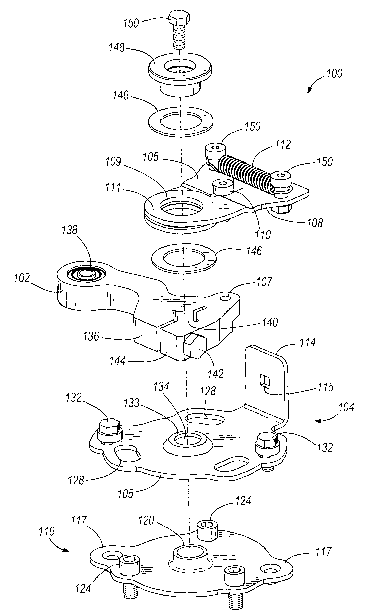
[0018] FIG. 6 an exploded diagram illustrating the centering mechanism of FIG.
4.
[0019] FIG. 7A is a plan view of an illustrative embodiment of a first bracket
of the
centering mechanism of FIG. 6.
100201 FIG. 7B is a cross-sectional view of the first bracket of FIG. 7A taken
along line
7B-7B.
[0021] FIG. 7C is a side elevational view of the first bracket of FIG. 7A with
a cross-
sectional view of a feature configured to accept a threaded fastener.
[0022] FIG. 8A is a plan view of the second bracket of the centering mechanism
of FIG. 6,
which is configured to engage the first bracket.
[0023] FIG. 8B is a cross-sectional view of the second bracket of FIG. 8A
taken along line
8B-8B.
4
CA 02661854 2009-02-25
WO 2008/028007 PCT/US2007/077182
100241 FIG. 8C is a side elevational view of the second bracket of FIG. 8A
viewed fi-om line
8C-8C.
[00251 FIG. 9A is a plan view of a conti-ol arm that is configured to engage
the input shaft of
the hydraulic pump of FIG. 4.
[0026] FIG. 9B is a side elevation view of the control arm of FIG. 9A viewed
from line 9B-
9B, illustrating an aperture configured to accept a threaded fastener.
[0027] FIG. 10 is a cross-sectional view of the right drive puinp of the
tandem hydraulic
pump assembly of FIG. 4 taken along a centerline axis of the input shaft and
illustrating the
positioning of the centering mechanism and control an-n relative to the input
shaft of the right
drive pump.
[0028] FIG. 1 IA is a plan view of a centering ann of the centering mechanism
of FIG. 6.
[0029] FIG. I 1 B is a perspective view of the centeiing arm of FIG. 11 A.
[0030) FIG. 11C illustrates a pair of centering arms positioned adjacent one
another as in the
centering mechanism of FIG. 6.
[0031] FIG. 12 is a perspective view of a tandem hydraulic pump assembly
illustrating a
centering mechanism of an alternative illustrative embodiment coupled to an
input shaft of one
of the hydraulic puinps.
[0032] FIG. 13 is another perspective view of the tandem hydraulic pump
assembly of FIG.
12.
[00331 FIG. 14 an exploded diagram illustrating the centering mechanism of
FIG. 12.
[0034] FIG. 15 is a plan view of an alternative illustrative embodiment of a
second bracket of
the centering mechanism of FIG. 14.
[0035] FIG. 16 is a plan view of an alternative illustrative einbodiment of a
first bracket of
the centering mechanism of FIG. 14.
CA 02661854 2009-02-25
WO 2008/028007 PCT/US2007/077182
[0036) Before any featui-es and at least one embodiment of the invention are
explained in
detail, it is to be understood that the invention is not limited in its
application to the details of
construction and the aiTangements of the components set foi-th in the
following description and
claims or illustrated in the drawings. The invention is capable of other
embodiments and of
being practiced or being carried out in various ways. Also, it is understood
that the phraseology
and terminology used herein is for the puipose of description and should not
be regarded as
limiting.
100371 The use of "including", "having", and "comprising" and variations
thereof herein is
meant to encompass the items listed thereafter and equivalents thereof as well
as additional
items. The use of letters to identify elements of a method or process is
simply for identification
and is not meant to indicate that the elements should be perfonned in a
particular order.
DETAILED DESCRIPTION
100381 A power machine 10, of the type in which incorporation of the present
disclosure is
useful, is illustrated generally in FIGs. 1 and 2. As shown, power machine 10
includes a main
frame assembly 16, lift ai-in assembly 30 and operator coinpartment 40. A pair
of wheels 12,
which are mounted to stub axles 14, extend from both sides of main frame 16.
[00391 Lift ann assembly 30 is mounted to upright members 20 of main frame
assembly 16.
As shown, lift artn assembly 30 includes a pair of lift arms 32, which overlie
wheels 12. Lift
anns 32 are attached to each other by a cross member 33, and are pivotally
mounted at a
rearward end to upright members 20. Lift ann assembly 30 is configured to be
pivotally attached
to an attachment such as bucket 34. Lift arm assembly 30 is raised and lowered
with respect to
main frame assembly 16 by actuating a pair of lift cylinders 36. Each of the
lift cylinders 36 has
a first end pivotally mounted to one of upright members 20 and a second end
pivotally mounted
to one of lift anns 32. Bucket 34 is rotated with respect to lift ai-ms 32 in
a known manner by
actuating one or more bucket tilt cylinders (not shown).
100401 Operator compartment 40 is defined and partially enclosed by a cab 42.
Cab 42
includes side panels 44, overhead panel 46, rear panel 48, and seat pan 52
upon which seat 54 is
mounted. Cab 42 is an integral unit and is pivotally mounted at its rear to
main frame assembly
16. Cab 42 is positioned above an engine compartment (not shown) that is
located within the
6
CA 02661854 2009-02-25
WO 2008/028007 PCT/US2007/077182
main frame assembly 16. Drive control actuators 58, which, in the illustrated
embodiment are
pivotable levers, are positioned within the operator compartment 40. By
manipulating each of
the drive control actuators 58, such as by moving them in a forward or
rearward direction, the
operator can control a hydraulic drive system, located in the engine
compartment and described
in more detail below. The hydraulic drive system causes the power machine 10
to move in a
forward or reverse direction.
[0041] In the illustrative embodiment, shown in FIGs. I and 2, power machine
10 is a skid
steer loader, and an operator uses drive control actuators 58 to control both
the movement and
the steering of the power machine 10. Power machine 10 is not limited by any
particular feature
of the skid steer loader shown in FIGs. 1 and 2. As one example, the drive
control actuators 58
need not be pivotable levers but can be any type of actuation device. In
addition, power machine
can be any type of vehicle that incorporates a hydraulic drive system, such as
a mini
excavator, a wheeled loader, a utility vehicle, to name a few non-limiting
examples.
[0042] FIG. 3 is a block diagram illustrating a hydraulic drive system 80
suitable for use in
power machine 10. Hydraulic drive system 80 includes a hydraulic pump assembly
60, which, in
the illustrative embodiment, includes a left drive pump 62 and a right drive
pump 64. For the
purposes of this disclosure, the left drive pump 62 powers the drive on the
left hand side of the
power machine 10, and the right drive pump 64 powers the drive on the right
hand side of the
power machine 10. A drive control actuator 58, located in the operator
compartment 40 (shown
in FIG. 2), is coupled to each of the left drive pump 62 and the right drive
puinp 64 via links 22.
Links 22, in the illustrated embodiment, include a rigid link operably coupled
to both the drive
control actuator 58 and one of the left and right drive pumps 62 and 64.
Actuation of one of the
drive control actuators 58 in a forward or reverse direction is communicated
via one of the links
22 to left drive pump 62 or to right drive pump 64.
[0043] When the left drive pump 62 has been actuated by its corresponding
drive control
actuator 58, the left drive puinp 62 pumps hydraulic oil into the hydraulic
motor 66A via a
hydraulic link 70 such as a hose. Hydraulic motor 66A is operatively coupled
to a transfer
mechanism 68, which in turn is coupled to a pair of axles 14A and 14B. Oil
flow into the
hydraulic motor 66A causes the hydraulic motor 66A to provide a rotational
force to the transfer
7
CA 02661854 2009-02-25
WO 2008/028007 PCT/US2007/077182
mechanism 68. Transfer mechanism 68, in turn, causes the axles 14A and 14B to
rotate in a
forward or reverse direction depending upon the direction of the oil flow into
the hydraulic
motor 66A. Axles 14A and 14B are coupled to wheels 12A and 12B, which turn
with the axles
14A and 14B to cause the power machine 10 to move.
[00441 Transfer mechanism 68 can be any suitable structure capable of
transmitting an
output of the hydraulic inotor 66A to the axles 14A and 14B. For example, the
transfer
mechanism 68 can include an assembly of gears and chains configured to
operably couple both
of the axles 14A and 124B to the output of hydraulic motor 66A to drive the
axles 14A and 14B
in tandem. Alternatively, any other structure can be provided to transfer the
output of the
hydraulic motor 66A to either axle 14A or axle 14B, or both.
100451 Similarly, the right drive pump 64 is coupled to a hydraulic motor 66B
via a hydraulic
link 72. Hydraulic motor 66B has an output that is coupled to a transfer
mechanism 69. Transfer
mechanism 69, in turn, is coupled to axles 14C and 14D. Axles 14C and 14D are
coupled to
wheels 12C and 12D. Thus, actuation of the drive control actuator 58 in
communication with
right drive pump 64 causes oil to be pumped, via hydraulic link 72, into
hydraulic motor 66B.
Depending on the direction of oil pumped into hydraulic motor 66B, the wheels
12C and 12D
will be driven in a forward or reverse direction. Transfer mechanism 69 can
also be any suitable
structure capable of transmitting an output of the hydraulic motor 66B to the
axles 14C and 14D.
(0046] The drive system 80 illustrated in FIG. 3 is shown for illustrative
purposes only.
Other drive systems may be incorporated into power machine 10. For example,
power machine
can include a hydraulic motor dedicated to each of the wheels on the machine.
Thus, each
wheel can be independently driven by one of the left and right drive pumps.
Similarly, the
hydraulic pump assembly can have a single hydraulic drive pump that controls
either the front
two or rear two wheels for a two-wheel drive power machine 10. Aiternatively
still, the front
wheels and rear wheels can each be driven together by a hydraulic puinp
assembly having a
single hydraulic drive pump or tandem hydraulic drive pumps to provide four-
wheel drive.
100471 FIGs. 4 and 5 illustrate a hydraulic pump assembly 60 of the type
described above
with respect to FIG. 3. Hydraulic pump assembly 60 includes left drive pump 62
and right drive
pump 64. A front side 61 of the hydraulic pump asseinbly 60 is shown in FIG.
4, and a back side
8
CA 02661854 2009-02-25
WO 2008/028007 PCT/US2007/077182
63 of the hydraulic pump assembly 60 is shown in FIG. 5. Each of the left
drive pump 62 and
right drive pump 64 has a housing 67 with a pair of ports 92 therein, which
are configured to be
coupled via hydraulic links 70 and 72 to hydraulic motors 66A and 66B,
respectively, as is
shown in FIG. 3. Hydraulic oil is pumped under pressure through ports 92 from
each of the left
drive pump 62 and the right drive pump 64 to their respective hydraulic motors
66A and 66B.
The direction of the hydraulic flow from the ports 92 depends on whether the
respective drive
pump has been actuated in a forward or reverse direction.
[0048] On the back side 63 of the hydraulic drive pump systein 60, a port 94
is shown
between the left drive pump 62 and the right drive pump 64. Port 94 is an
inlet, which is
configured to be coupled to a hydraulic oil supply (not shown). The hydraulic
oil supply
provides oil to each of the left drive pump 62 and the right drive pump 64. In
addition, a pair of
ports 96 is shown. Each of the ports 96 are adapted to be coupled to a
hydraulic reservoir (not
shown) to return oil from the respective hydraulic drive pumps to the
reservoir.
(0049] Left drive pump 62 has a pintle ann or input shaft 88 that extends
through a trunnion
cap 95 that is fastened to the housing 67 of the left drive pump 62. Input
shaft 88 engages an
internal mechanism such as a swash plate (not shown) located inside the
housing 67. The input
shaft 88 is rotatable to cause the internal mechanism to move and direct oil
within the left drive
pump 62. Input shaft 88 has a centered or neutral position. In the neutral
position, the swash
plate is positioned so that no oil is pumped out of the ports 92, and thus,
the wheels 12A and 12B
are not driven by the left drive pump 62. In one illustrative embodiment,
rotating the input shaft
88 in a clockwise direction will cause the internal mechanism to move and
direct oil through the
ports 92 to hydraulic motor 66A to cause wheels 12A and 12 B to move in a
forward direction.
Rotating the input shaft 88 in a counter-clockwise direction will cause the
wheels 12A and 12B
to move in a reverse direction.
[0050] Right drive pump 64 is similarly configured with an input shaft 88
(FIG. 10) that
extends through a trunnion cap 95 and is coupled to an internal mechanism such
as a swash plate
(not shown). Right drive pump 64 is shown in FIGs. 4 and 5 with a pintle lever
or control ann
102 attached to the input shaft 88. Control ar-m 102 is also adapted to be
coupled to link 22 (FIG.
3). Control arm 102 thus transfers an operating force transmitted from the
drive control actuator
9
CA 02661854 2009-02-25
WO 2008/028007 PCT/US2007/077182
58 through link 22 to the input shaft 88 to cause the input shaft 88 to rotate
when such a force is
applied.
[0051] A centering mechanism 100 is attached to the right drive pump 64.
Centering
mechanism 100 engages the control arm 102 to provide a centering force to
assist the control ai-in
102 to move the input shaft 88 to the neutr-al position when no operating
force is applied to the
control arnl 102 from the drive control actuator 58. It is to be understood
that a control aim 102
and centei-ing mechanism 100 of the type attached to the right drive puinp 64
is also to be
attached to the left drive pump 62. The hydraulic pump assembly 60 is shown in
FIGs. 4 and 5
with just one centering mechanism 100 for illustrative puiposes only.
100521 Each centering mechanism 100 includes a first bracket 116. The first
bracket 116 is
adapted to be fixedly attached to the trunnion cap 95. Each of the left drive
pump 62 and the
right drive pump 64 have a trunnion cap 95, and thus a first bracket 116 is
attached to each
trunnion cap 95. Fasteners 98, which are engaged with the puinp housing 67 to
secure the
trunnion cap 95 to the pump housing 67, are removed, and first bracket 116 is
positioned upon
the trunnion cap 95. Both the trunnion cap 95 and the first bracket 116 are
then secured to the
housing 67 by a plurality of fixing fasteners 124 that extend through
apertures 122 in the first
bracket 116 as well as through the trunnion cap 95.
(0053) A second bracket 104 is mounted onto the first bracket 116. Second
bracket 104 is
rotatably adjustable with respect to the first bracket 116. Second bracket 104
includes a
generally planar body or primary portion 105 and a tab 114, which extends
angularly away from
the generally planar primary portion 105. Primary portion 105 is aligned so
that when the
second bracket 104 is mounted onto the first bracket 116, the primary portion
105 is positioned
adjacent to the first bracket 116, and the tab 114 extends away from the first
bracket 116.
Second bracket 104 has a pair of slots 130 that extend through the primary
portion 105 and
though each of which an adjusting fastener 132 extends to engage the first
bracket 116 to secure
the second bracket 104 to the first bracket 116. The slots 130 allow for some
adjustment of the
second bracket 104 with respect to the first bracket 116 when the fasteners
132 are not finnly in
place. When the fasteners 132 are firmly in place, the second bracket 104 is
securely fastened to
the first bracket 116.
CA 02661854 2009-02-25
WO 2008/028007 PCT/US2007/077182
100541 Control ann 102 is configured to be positioned adjacent to the second
bracket 104 and
be secured to the input shaft 88. First centering ai-i-n 106 and second
centering arm 108 are
positioned adjacent the control ann 102. A bushing 148, which is fastened by a
fastener 150 to
the input shaft 88, captures the first and second centering aims 106 and 108
between the bushing
148 and the control arm 102. The bushing 148 also provides a rotating fulcrum
for the first and
second centering arms 106 and 108 so that they are rotatable with respect to
the input shaft 88.
[0055] Each of the first centering ai-rn 106 and the second centering ai-in
108 extend away
from the input shaft 88 and are positioned so that they are on opposite sides
of tab 114. A coil
spring 112 is attached to each of the fist centering arm 106 and the second
centering arm 108.
The coil spring 112 exerts a force on each of the first centering ann 106 and
the second centering
ann 108 that tends to pull the two centering anns 106 and 108 together. When
no other force is
acting upon the first centering arm 106 and the second centering ann 108, they
are pulled
together until each of the centering anns 106 and 108 engages tab 114.
100561 A fastener 110 extends into the control arm 102 so that it is
positioned between and is
capable of engaging the first and second centering anns 106 and 108. When the
control ai-i-n 102
moves from the neutral or centered position, for example, towards the front
side 61 of hydraulic
puznp assembly 60, the fastener 110 rotates with the control arm 102 in a
clockwise direction and
engages centering ann 108. The force applied by the coil spring 112 against
centering ann 108
is overcome and the centering ai-in 108 is rotated away from the tab 114 along
with the control
arm 102. When forces, such as the actuation of the drive control actuator 58
that can act on the
control ai-i-n 102, are removed, the coil spring 112 urges the second
centering arm 108 toward the
first centering ann 106 until the second centering arm 108 engages tab 114.
100571 When tab 114 is properly positioned and the first centering arm 106 and
the second
centering ann 108 are positioned to engage the tab 114, the centering arins
106 and 108 urge the
control ann 102 to move the input shaft 88 into the neutral position.
Adjustment of the second
bracket 104 with respect to the first bracket 116, therefore, rotates tab 114,
which defines the
position of the input shaft 88 when no other force is acting upon the control
ann 102. Thus, if
the tab 114 is properly adjusted, the input shaft 88 will return to the
neutral position when no
other force is acting upon the control ai-i-n 102. As described above, the
second bracket 104 can
11
CA 02661854 2009-02-25
WO 2008/028007 PCT/US2007/077182
be adjusted with respect to the first bracket 116 to position the tab 114 so
that it is properly
positioned.
100581 FIG. 6 is an exploded view of centering mechanism 100 and control ann
102. First
bracket 116 (also shown in FIGs. 7A-7C) has a plurality of apertures 122,
which are positioned
to be aligned with similar apertures in the trunnion cap 95 so that fasteners
124 can extend
through the first bracket 116 and the trunnion cap 95 to secure both
components to the housing
67. First bracket 116 includes a pair of flanges 117, which are positioned to
extend beyond the
outer perimeter of trunnion cap 95. A boss 118 extends into each of the
flanges 117. Each boss
118 is adapted to accept a threaded fastener 132 to secure the second bracket
104 to the first
bracket 116. In one illustrative embodiment, boss 118 is extruded into the
first bracket 118 and
is provided with a thread to accept threaded fastener 132. However, the boss
118 can be formed
in any manner and need not be provided with threads.
(00591 First bracket 116 also includes a formation 120 with an aperture 119
extending
therethrough to allow the first bracket 116 to be fitted over the input shaft
88. The aperture 119
is large enough so that the first bracket 116 does not engage the input shaft
88. The formation
120 includes a lip 121, which is shaped to engage the second bracket 104 so
that the second
bracket 104 can be positioned properly with respect to the first bracket 116
and the input shaft
88.
(0060] The second bracket 104 (also shown in FIGs. 8A-8C) is configured to be
positioned
adjacent and be attached to the first bracket 116. Second bracket 104 includes
a protrusion 133
fonned into the generally planar primary portion 105 of the second bracket
104. Protrusion 133
can be exti-uded into the second bracket 104 and includes an aperture 134 that
is sized so that the
proti-usion 133 fits over the feature 120 and engages the lip 121 on the first
bracket 116. The
second bracket 104 is thus centered on the first bracket 116 and is capable of
rotating on the
feature 120. The relationship between the lip 121 and the proti-usion 133
(shown in FIG. 10)
centers the second bracket 104 relative to the first bracket 116 and the input
shaft 88, thereby
preventing the second bracket 104 from moving off center when it is being
adjusted.
100611 The second bracket 104 further includes a plurality of slotted
apertures 128. The
slotted apertures 128 are positioned to fit over the fasteners 124, which hold
the first bracket 116
12
CA 02661854 2009-02-25
WO 2008/028007 PCT/US2007/077182
to the housing 67. This allows the second bracket 104 to be able to rotate
with respect to the first
bracket 116 without any intei-ference from the fasteners 124.
100621 Second bracket 104 further includes a pair of slots 130 each of which
are sized to
accept a fastener 132. Fasteners 132 are also configured to engage threaded
boss 118 in the first
bracket 116 to secure the second bracket 104 to the first bracket 116. When
the fasteners 132 are
not snuggly fitted onto the second bracket 104, the second bracket 104 is
capable of rotating with
respect to the first bracket 116 within the confines of slots 130 to properly
position tab 114.
When the fasteners 132 are snuggly tightened, the second bracket 104 is fii-
mly lleld in position
with respect to the first bracket 116.
[0063] Tab 114 includes an aperture 115 extending therethrough. Aperture 115
is configured
to accept a tool such as a screwdriver or other similar instrument. By
inserting an instrument
into the aperture 115 when the fasteners 132 are not snugly tightened to the
second bracket 104,
the second bracket 104 can be easily rotated in one direction or the other to
find a proper position
for the tab 114.
100641 Control ann 102 (also illustrated in FIGs. 9A-9B) is positioned
adjacent the second
bracket 104. Control ann 102 includes an aperture 140 that is sized and shaped
to accept and be
engaged with the input shaft 88. Control arm 102 also includes a slot 144 that
extends from
aperture 140 to an outer surface 136 of the control ann 102. Slot 144 divides
a portion of the
control ann 102 into first and second fingers 160 and 162, respectively. A
cross bore 164
extends through first finger 160 and into second finger 162. Cross bore 164 is
configured to
accept a fastener 142. Fastener 142 is capable of engaging the cross bore 164
so that it is fixedly
attached to the control aim 102. When fastener 142 is engaged with control ai-
m 102, tightening
the fastener 142 causes the control ann 102 to defonn slightly at the slot 144
to snuggly fit the
control ann 102 onto the input shaft 88. Control ann 102 also includes a
linkage engagement
member 138, which is configured to accept and be attached to link 22.
100651 Control ann 102 is thus rotatable with respect to the first and second
brackets 116 and
104. When a force from the drive control actuator 58 is transmitted via link
22 to the control arm
102, the control arm 102 rotates towards the forward direction 61 or the
reverse direction 63.
The control ann 102 thus rotates the input shaft 88 with respect to the
casting 67, causing the
13
CA 02661854 2009-02-25
WO 2008/028007 PCT/US2007/077182
internal mechanism to move and direct oil to the particular hydraulic motor
through the orifices
92.
100661 First and second centering anns 106 and 108 are positioned adjacent the
control ann
102. Each of the first and second centering arms 106 and 108 has an aper-ture
109 extending
through a first end 111 of the respective arms. The aperture 109 in each of
the first and second
centering ai-ms 106 and 108 is large enough to fit over the input shaft 88
without engaging the
input shaft 88. Bushing 148 provides a retaining force onto the first and
second centering anns
106 and 108 to hold the centering arms 106 and 108 in position with i-espect
to the control arm
102. Spacers 146 are positioned between the control arm 102 and the first
centering ann 106 as
well as between the first centering ann 106 and the second centering arm 108.
Another spacer
146 is positioned between the second centering ann 108 and the bushing 148.
Spacers 146
prevent metal-to-metal contact between the control arm 102, first and second
centering anns 106
and 108 and bushing 148.
[0067] Returning again to FIG. 6, each of the first and second centering anns
106 and 108
has a member 150 on a second end of the centering ann 106 and 108 adapted to
accept and
secure coil spring 112. Spring 112 is positioned between the first and second
centering anns 106
and 108 and acts to pull the first and second centering anns 106 and 108
toward each other. A
fastener I 10 is fitted into the control arm 102 at an aperture 107. The
fastener 110 is positioned
so that it is capable of engaging either the first centering ann 106 or the
second centering ann
108 when the control aim 102 rotates with respect to the first and second
brackets 116 and 104.
Thus, the fastener 110, which moves with the control ann 102 acts against the
spring 112 to
separate the first centering ann 106 from the second centering ann 108.
[0068) When a force from the drive control actuator 58 is removed, the spring
112 tends to
pull the first centering ann 106 and the second centering ann 108 together
until they are both
engaging the tab 114 of the second bracket 104. It is to be understood that
depending on the
direction of rotation of control ann 102, fastener 110 will engage either the
first centering a1-in
106 or the second centering ann 108.
[00691 FIGs. 11 A-11 C illustrate the first and second centering ai-ms 106 and
108 in more
detail. In the illustrative embodiment, the first center-ing arin 106 and the
second centering ann
14
CA 02661854 2009-02-25
WO 2008/028007 PCT/US2007/077182
108 are identical or nearly identical. The first and second centering arms 106
and 108 include an
aperture 166 on a second end that is capable of accepting membei- 150 to
provide an attachment
point on each of the first and second centering arms 106 and 108 for coil
spring 112. As shown
in FIG. 6, member 150 can be a fastener system, such as a nut and bolt ai-
rangement, that is
attached at the aperture 166. The first and second centering ai-ms 106 and 108
are shown aligned
together in FIG. 11 C.
[0070) FIGs. 12-16 illustrate an alternative illustrative embodiment of a
portion of the
centering mechanism 100. In FIGs. 12-16, the pump assembly 60 and the
centering mechanism
100 are similar to that described above with respect to FIGs. 1-11 C. Common
elements have the
same reference number, and modified elements have the same reference number
""'.
100711 FIG. 15 illustrates an alternative construction of the second bracket
104', and FIG. 16
illustrates an alternative construction of the first bracket 116'. In the
alternative construction, the
second bracket 104' defines three adjusting slots 130', and the first bracket
116' correspondingly
defines three bosses 118'. As shown in FIG. 14, three adjusting fasteners 132'
are provided to
adjustably connect the second bracket 104' to the first bracket 116'.
[0072] In the illustrated alternative embodiment, the tab 114' of the second
bracket 104'
defines a pair of apertures 115'. A tool (or more than one tool) may engage
one or both of the
apertures 115' and be used to adjust the second bracket 104' relative to the
first bracket 116'.
[0073] In the illustrated alternative embodiment, the bosses 118' defined in
the first bracket
116' do not depend below the lower surface of the first bracket 116'. Also, in
the illustrated
alternative embodiment, the second bracket 104' and the first bracket 116' are
not provided with
the cooperating protrusion 133 and lip 121, described above. It should be
understood, however,
that such structure may be provided for this alternative embodiment. With
these modifications,
the first bracket 116' and the second bracket 104' (with the exception of the
tab 114') are
substantially planar.
[0074) The illustrative embodiments provide for a centering system on a
hydraulic drive
pump that is easy to adjust. Merely by teinporarily loosening fasteners 132
and engaging
aperture 115 to move or rotate the second bracket 104 with respect to the
first bracket 116, the
CA 02661854 2009-02-25
WO 2008/028007 PCT/US2007/077182
centering mechanism 100 can be easily adjusted so that that it is pi-operly
positioned. Thus,
when there is no force applied on the control arm 102 by the operator through
drive control
actuators 58, the centering mechanism 100 will urge the input shaft 88 to a
neutral position. The
arrangement allows for an easily adjustable centering mechanism that is
amenable to small
adjustments.
[0075] Although the present disclosure has been described with reference to
the preferred
embodiments, workers skilled in the art will recognize that changes may be
made in form and
detail without departing from the spirit and scope of the disclosure.
16