Note : Les descriptions sont présentées dans la langue officielle dans laquelle elles ont été soumises.
CA 02665219 2009-04-01
WO 2009/020464
PCMS2007/078918
CONDUCTIVE PATTERNS AND METHODS OF USING THEM
HELD OF THE TECHNOLOGY
[0001] Embodiments of the technology disclosed herein relate generally to
conductive
patterns and methods of using and printing them. More particularly, certain
embodiments
relate to electronic devices, such as printed circuit boards, that include one
or more
conductive patterns as disclosed herein.
BACKGROUND
[0002] Electronic devices include numerous connected electrical circuits. As
the footprint of
devices becomes smaller, the circuitry of the devices must be reduced to
accommodate a
desired footprint. Current methods uscd to producc circuits and conductors do
not provide
the precision to create narrow and thin conductors for use in many small
electronic devices.
SUMMARY
[0003] In accordance with a first aspect, a device comprising at least one
conductive pattern
is disclosed. In certain embodiments, the conductive pattern may take the form
of one or
more conductive lines which may be electrically coupled to one or more other
conductive
lines. In certain examples, the conductive pattern may be produced by
disposing a support on
a substrate, disposing a conductive material between the support, and removing
the support.
Conductive patterns produced using such a method are referred to in some-
instances herein as
high-aspect ratio conductive patterns. In some examples the conductive
material may be a
metal particles, such as the capped metal particles described herein.
[0004] ln accordance with an additional aspect, a substrate comprising at
least one high-
aspect ratio conductive pattern is provided. In certain examples, the
substrate may be part of
a printed circuit board. In some examples, the substrate may be formed from
one or more
pre-pregs that have been thermally treated. In other examples, the substrate
may take the
form of a laminate or a molded article. In certain embodiments, the conductive
pattern may
include one or more conductive lines which may be electrically coupled to one
or more other
conductive lines. The conductive pattern may be disposed horizontally along
the plane of the
substrate, vertically and substantially perpendicular to the plane of the
substrate or at any
angle to the plane of the substrate. In certain configuration a first high-
aspect ratio
conductive pattern may be electrically coupled to another conductor, which may
be a high-
aspect ratio conductive pattern, on an opposite or other face of the
substrate.
- 1 -
CA 02665219 2016-07-05
56222-1
[0005] In accordance with another aspect, a printed circuit board comprising
at least one high
aspect ratio conductive line is provided. In certain examples, the printed
circuit board rnay bc
formed from one or more prepregs that include at least one high-aspect ratio
conductive
pattern disposed on one of the prepregs.
[0006] In accordance with another aspect, a method of producing a high-aspect
ratio
conductive pattern is disclosed. In certain examples, the method includes
disposing a
conductive material between a solid support. In certain examples, the solid
support may
include a defined spacing to provide a conductive pattern with a desired
geometry, thickness
or width. The method may also include removing the solid support to provide a
high-aspect
ratio conductive pattern. In certain examples, the solid support may be
removed by thermal
treatment, chemical treatment or other methods that may remove the solid
support without
damage to the conductive pattern. In certain examples, the solid support may
include a anti-
wetting coating to prevent or reduce the tendency of the ink to spread.
[0007] In accordance with another aspect, a method of producing a printed
circuit board
comprising at least one high-aspect ratio conductive pattern is provided. In
certain examples,
the method includes disposing a conductive material between a solid support on
a
prepreg ,and removing the solid support from the prepreg to provide a high-
aspect ratio
conductive pattern. The method may also include thermally treating the prepreg
with the at
least one disposed high-aspect ratio conductive pattern to provide a printed
circuit board.
[0008] In accordance with an additional aspect, a method of facilitating
assembly of an
electronic device is disclosed. In certain examples, the method comprises
providing at least
one ink comprising capped metal particles, and providing instructions for
disposal of the at
least one ink on a substrate to provide a high-aspect ratio conductive pattern
on the substrate.
[0009] in accordance with another aspect, a method of printing a conductor
using a printer is
provided. In eertain examples, the method comprises disposing a solid support
material in a
first reservoir of the printer on a substrate. In some examples, the method
further comprises
disposing an ink in a second reservoir of the printer between the disposed
solid support
material on the substrate. In certain examples, the method may also include
removing the
disposed solid support material from the substrate.
- 2 -
81614558
[0009a] In accordance with another aspect, the invention provides a method for
producing a
high-aspect ratio conductive pattern on a substrate with a solid support
having a defined
spacing comprising: applying a first support layer on the substrate to form a
solid support
defining a spacing having an effective height; printing a first conductive ink
material layer to
fill the defined spacing of the solid support on the substrate; applying a
second support layer
to the first support layer to increase the effective height of the spacing
defined by the solid
support; printing a second conductive ink material layer to reach the
increased effective height
of the spacing defined by the solid support; and removing all of the solid
support layers to
provide the high-aspect ratio conductive pattern.
[0009b] In accordance with another aspect, the invention provides a method of
producing a
printed circuit board comprising: printing a first layer of conductive ink
material to fill a
defined spacing of a solid support on a prepreg; increasing an effective
height of the defined
spacing of the solid support; printing a second layer of conductive ink
material to fill the
defined spacing to reach the increased effective height; and removing the
solid support on the
prepreg to provide a high-aspect ratio conductive pattern.
[0010] Additional features, aspects and examples are described in more detail
below.
2a
CA 2665219 2017-06-29
CA 02665219 2009-04-01
WO 2009/020464 PCT/US2007/078918
BRIEF DESCRIPTION OF THE FIGURES
[0011] Certain embodiments are described below with reference to the
accompanying figures
in which:
[0012] FIG. 1 is a drawing of solid supports disposed on a substrate, in
accordance with
certain examples;
[0013] FIG. 2 is a drawing of a conductive material disposed between solid
supports on a
substrate, in accordance with certain examples;
[0014] FIG. 3 is a drawing of a high-aspect ratio conductive pattern disposed
on a substrate,
in accordance with certain examples;
[0015] FIG. 4 shows a method for producing a high-aspect ratio conductive
pattern, in
accordance with certain examples; and
[0016] FIG. 5 is an example of a printed circuit board including a high-aspect
ratio
conductive pattern, in accordance with certain examples.
[0017] Certain features shown in the figures may have been enlarged,
distorted, altered or
otherwise shown in non-conventional manner to facilitate a better
understanding of the
technology disclosed herein.
DETAILED DESCRIPTION
[0018] Certain embodiments of the devices and methods disclosed herein provide
electrically
conducting patterns having electrical properties not previously achieved with
existing
methods. High-aspect ratio conductive patterns may be produced on any type of
electrical
device in any desired pattern of selected thicknesses and widths. Illustrative
high-aspect ratio
conductive patterns are disclosed below.
[0019] Piezoelectric inkjet technology has advanced to become a key enabler in
printed
electronics. As an additive process, inkjet printing precisely controls the
order and amount of
fluids applied so expensive fluids and materials are not wasted. As an
extended range of
jettable nanoparticle conductive, semi-conductive, and adhesive fluids become
commercially
available, new opportunities for inkjet are emerging in the electronic
industry.
[0020] Piezoelectric inkjet technology has advanced to become a key enabler in
printed
electronics. As an additive process, inkjet printing precisely controls the
order and amount of
fluids applied so expensive fluids and materials are not wasted. As an
extended range of
jettable nanoparticle conductive, semi-conductive, and adhesive fluids become
commercially
available, new opportunities for inkjet are emerging in thc electronic
industry.
- 3 -
CA 02665219 2015-06-23
50860-244
[0021] One drawback in inkjet technology is printing of narrow (less than
about 100 microns
wide) and thick lines (more than about 2 microns thick). Normally to achieve
required line
thickness multiple printing passes are needed which could result in spreading
the line beyond
the required width. The phenomenon can be especially severe in the case of
conducting
metallic inks. Metal particles are much denser then the carrier media
therefore most of the ink
volume is taken by solvents which readily spread on the printed surface.
[0022] To prevent the ink spread common practice is the addition of rheology
modifiers to
increase the viscosity and tackiness of the ink. However, the addition of
rheology modifiers
(usually high boiling organic materials and polymers) to the conductive ink
formulation may
result in a significant degradation of the conductivity of the printed lines.
This is especially
true in the case of the metallic nanoparticle inks, such as
those described in U.S. Application No. 11/462,089. The sintering of
nanoparticles into highly conductive lines relies on the intimate
contact between the nanoparticles so addition of high boiling organic
materials and polymers
can impede or completely block the sintering process resulting in poor quality
lines.
[0023] In accordance with certain examples, a method that provides for ink jet
printing of
fine patterns of any dimensions with inks of any viscosity to provide a high-
aspect ratio
conductive pattern is disclosed. The term "high-aspect ratio" refers to the
electrical
conductor as having a first dimension, e.g., a height, that is at least about
five times greater
than a second dimension, e.g., a width. In ccrtain examples, the first
dimension is at least
about 10, 20, 30, 40, 50, 60, 70, 80, 90 or 100 times greater than the second
dimension. The
method used herein, however, may also be used to print conductive patterns
having heights
and widths that are substantially the same, e.g., 1:1 ratio of height:width or
conductive
= patterns where the height is about twice that of the width, e.g., 2:1
ratio of height:width.
[0024] In accordance with certain embodiments, the conductive material may be
disposed
between two or more supports. For example and referring to FIG. 1, a side-view
of a
substrate 100 is shown. A first solid support 110 and a second solid support
120 have been
disposed on the substrate 100. Though solid supports 110 and 120 are shown as
being
disposed near the center of the substrate 100, the solid supports 110 and 120
rnay he disposed
at any portion or area of the substrate 100. Subsequent to disposal of the
solid support 110
and 120 on the substrate 110, a conductive material 130 may be disposed
between the solid
support 110 and 120, as shown in FIG. 2. The height hi of the solid supports
and the distance
d1 between the solid supports generally determines the thickness and width of
the conductive
- 4 -
CA 02665219 2009-04-01
WO 2009/020464
PCT/US2007/078918
material, respectively. By decreasing the distance di, the width of the
conductive pattern will
decrease. By decreasing the height hi, the thickness of the conductive pattern
will decrease.
The actual thickness and width of the conductive pattern may vary and
illustrative
thicknesses range from about 0.001 mm to about 0.1 mm and illustrative widths
include, but
are not limited to, 0.05 mm to about 0.3 mm. Additional thicknesses and widths
will be
readily selected by the person of ordinary skill in the art, given the benefit
of this disclosure.
[0025] In accordance with certain examples, once the conductive material 130
is disposed
between the solid supports 110 and 120, the conductive material may be
subjected to one or
more treatment steps. In examples where the conductive material is a an ink
comprising
capped metal particles, such as the ones described below, the ink may be
sintered to condense
the disposcd material Other treatment steps include, but are not limited to,
heating, grinding,
chemical ctching, and plasma etching. Additional treatment steps to provide
high-aspect ratio
conductive patterns will be readily selected by the person of ordinary skill
in the art, given
the benefit of this disclosure.
[0026] In accordance with certain examples, various methods may be used to
dispose the
solid supports onto a substrate. The exact method used to dispose the solid
support material
onto a substrate may vary depending on the nature and properties of the
material selected for
use in the solid support. in examples where the solid support is a polymeric
material, the
solid support may be disposed by inkjet printing, screen printing, or gravure
printing. In
examples where the solid support is a paper based material, an inorganic salt
or an elastomer
such as rubber, the solid support may be disposed or packed in a mold or form
placed over
the substrate. Other suitable materials =for use in the solid support include,
but are not limited
to polymers, epoxy resins, inorganic/organic salts. In some examples when the
solid support
also provides anti-wetting properties it can be made of fluorinated polymers,
such as Krytox
fluids from Dupont or FluoroPel from Cytonix corporation. In some examples,
the solid
support may be disposed using an inkjet printer, such as an inkjet printer
that may be used to
dispose the conductive material. For example, the inkjet printer may include
two or more
reservoirs, one including the solid support material and the other including
the ink to be
printed between the solid supports. A first printing of the substrate may
dispose the solid
support material, and a second printing of the substrate may dispose the
conductive material
between the solid support material. Computer control of the printing operation
may provide
for known and precise disposal of both the solid support material and thc ink.
- 5 -
CA 02665219 2009-04-01
WO 2009/020464 PCT/US2007/078918
[0027] In accordance with certain examples, subsequent to disposal of the
solid support
material and the ink, the solid support material may be removed to provide a
high-aspect ratio
conductive pattern. In certain examples, the solid supports 110 and 120 may be
removed
from the substrate 100 to provide a high-aspect ratio conductive pattern 140,
as shown in FIG.
3. The exact method or process used to remove the solid supports depends on
the nature of
the material or materials used in the solid supports. In examples where the
solid support is a
polymer, such as a plastic, the polymer may be stripped by washing it with
organic solvents
such as isopropyl alcohol or acetone or commercial strippers available for
stripping
photoresist films. In certain examples, the solid supports may be grinded or
cut away with a
CNC machine or other device that may remove the solid supports without
substantial damage
to the disposed conductive material. In examples where the solid support is
paper, the solid
supports may be burned or ashed and an air stream may be used to remove the
residue from
the conductive material. In certain examples, the solid support may bc cast
using an
inorganic material, and, after disposition of the conductive material, the
inorganic material
may be dissolved away with a mild acid or base depending on the nature of the
inorganic
material. Illustrative inorganic materials include, but are not limited to,
sodium chloride,
potassium chloride, sodium nitratc and othcr watcr soluble salts.
[0028] In certain examples, the conductive material may be disposed step-wise,
followed by
subsequent disposal of more solid support material and subsequent disposal of
additional
conductive material. This process may be useful, for example, where it is
desirable to
achieve a conductive material thickness greater than is capable with a single
application. An
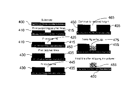
illustration of this process is shown schematically in FIG. 4. A substrate 400
is shown in FIG.
4, and a polymeric solid support material along with a conductive nanosilver
ink is shown as
being used. In a first step, supporting polymer line 410 and 415 are printed
on the substrate
400. A silver ink 425 is printed between solid support lines 410 and 415 until
it reaches the
top of solid support lines 410 and 415. Additional solid support material is
disposed on lines
410 and 415 to provide solid support lines 430 and 435. Additional ink 445 is
disposed
between solid support lines 430 and 435 until the ink reaches the top of the
solid support lines
430 and 435. Another step of disposing additional solid support material to
provide solid
support lines 450 and 455 followed by disposal of additional ink 465 may also
be performed.
This process of disposing solid support material followed by disposal of ink
may be
continued until a desired thickness is reached. Once a desired thickness is
reached, sintering
may be performed to condense the ink 465 to a sintered ink 475. Subsequent to
sintering,
- 6 -
CA 02665219 2009-04-01
WO 2009/020464 PCMS2007/078918
solid support lines 450 and 455 may be removed by washing the substrate in,
for example,
isopropyl alcohol, acetone or a mixture thereof to leave a substrate 400
having a high-aspect
ratio conductive pattern 485.
[0029] In accordance with certain examples, inks suitable =for use in the
methods disclosed
herein include, but are not limited to, any ink suitable for use in inkjet
printing applications.
Illustrative inks and particles for use in such inks are discussed below.
Additional suitable
inks will be readily selected by the person of ordinary skill in the art,
given the benefit of this
disclosure.
[0030] In accordance with certain examples, the ink may include silver
particles dispersed
in a suitable solvent system. Silver particles are well known materials and
available from
different commercial sources. Normally, the size of particles ranges from 5 to
70 nm. The
known advantage of particles compared to regular silver powder is their
ability to be heated
or sintered in solid structures at temperatures much lower then melting
tcmperaturcs. The
silver particles can be heated, for example, at temperatures as low as 200 C.
Thc hcating
proccss is a diffusion process in which silver migrates from particle to
particle forming
connecting bridges between particles. The structures formed by hcating of
currently
available silver particles are conductive, but their conductivity is still
much lower then that of
bulk silver. The reported conductivity is in the range of 1-2*104 S/cm
compared to 629 04
S/cm for the bulk silver. There remains a need for silver films whose
conductivity is much
closer to that of bulk silver.
[0031] In accordance with certain examples, particles suitable for use in the
inks disclosed
herein may be produced by mixing at least one metal or metal salt and a
capping agent in a
single phase solution or in a multi-phase solution. In certain examples, the
metal or metal salt
may be selected from conductive metals or conductive metal salts including,
for example,
transition metals or transition metal salts of gold, silver, copper, nickel,
platinum, palladium,
iron, and alloys thereof. The exact form of the metal or metal salt may vary
depending on the
selected solvent system. It is desirable that the metal salt dissolve in the
selected solvent
system without undue heating that could result in evaporation of the solvent.
Illustrative
anions of the metal salts include nitrate, chloride, bromide, iodide,
thiocyanate, chlorate,
nitrite, and acetate. Additional anions are disclosed below in reference to
the particular
illustrative metal salts disclosed.
[0032] In certain examples, the use of a single phase solution to produce the
particles
permits omission of a phase transfer reagent (though a phase transfer reagent
may still be
-7.-
CA 02665219 2009-04-01
WO 2009/020464
PCT/US2007/078918
used in certain embodiments) that is commonly used to produce particles in a
polyol process.
By performing the reaction in a single phase, the ease of producing the
particles increases,
and the cost of producing the particles decreases. In addition, large scale,
industrial synthesis
of the particles may be achieved using a single phase reaction. Additional
benefits of the
particles, and methods of producing them, will be readily selected by the
person of ordinary
skill in the art, given the benefit of this disclosure.
[0033] In accordance with certain examples, a silver salt may be used to
provide particle
suitable for use in the inks disclosed herein. In instances where a silver
salt is used, the silver
salt may be one or more of silver chloride, silver bromide, silver iodide,
silver thiocyanate,
silver sulfate, silver chromate, silver phosphate, silver oxalate, silver
carbonate, silver sulfite,
silver hydroxide, silver nitrate, silver chlorate, silver acetate, silver
nitrite, silver
acetylacetonate, silver lactate, silver (II) fluoride, silver (I)
hydrogenfluoride, silver (I)
permanganate, silver metavanadate, silver trifluoroacetate, potassium
dicyanoargentate, silver
benzoate, silver arsenate, silver bromate, silver cyclohexanebutyrate, silver
fluorosulfate,
silver hexafluoroantimonate (V), silver hexafluoroarsenate(V), silver
hexafluorophosphatc,
silver (I) fluoride, silver (I) oxide, silver (I) perrhenate, silver (1)
selenide, silver (I) telluride,
silver iodate, silver orthophosphate, silver sulfide, and silver tungstate.
Additional suitable
silver salts will be readily selected by the person of ordinary skill in the
art, given the benefit
of this disclosure.
[0034] In accordance with certain examples, a gold salt may be used to provide
particles
suitable for use in the inks disclosed herein. In instances where a gold salt
is used, the gold
salt may bc one or more of gold(III) chloride hydrate, hydrogen
tetrachloroaurate(III)
hydrate, chloro(dimethylsulfide)gold (I), gold (I) chloride, gold colloid,
gold (T) cyanide, gold
(I) iodide, gold (I) sulfide, gold (III) bromide hydrate, gold (III) chloride,
gold (III) chloride
trihydrate, gold (III) hydroxide, gold (III) oxide hydrate, gold (III)
sulfide, potassium
dicyanoaurate (I), potassium gold (III) chloride, and sodium
tetrachloroaurate(III) dehydrate.
Additional suitable gold salts will be readily selected by the person of
ordinary skill in the art,
given the benefit of this disclosure.
[0035] In accordance with certain examples, a copper salt may be used to
produce particles
suitable for use in the inks disclosed herein. In instances where a copper
salt is used, either
the cuprous form (copper (I)) or the cupric form (copper (II)) may be used.
Illustrative
copper salts include, but are not limited to, copper (I) chloride, copper (II)
chloride, copper
(I) bromide, copper (II) bromide, copper (I) iodide, copper (II) iodide,
copper mercuric
- 8 -
CA 02665219 2009-04-01
WO 2009/020464
PCMS2007/078918
iodide, copper (I) tetraiodomercurate (II), cuprous thiocyanate, copper (II)
sulfate, copper(II)
acetylacetonate, ammonium tetrachlorocuprate(II) dihydrate, copper aluminum
oxide, copper
chromite, ethylenediaminetetraacetic acid diammonium copper salt solution,
ethylenediaminetetraacetic acid copper(II) disodium salt, copper (I) acetate,
copper (I)
cyanide, copper (I) oxide, copper (I) selenide, copper (I) sulfide, copper (I)
telluride, copper
(I) thiophenolate, copper (II) acetate, copper(II) acetate hydrate copper (II)
acetate
monohydrate, copper (II) carbonate, copper (II) hydroxide, copper (II)
molybdate, copper (II)
niobate, copper (II) nitrate, copper (II) selenide, copper (II) selenite
dehydrate, copper (II)
sulfate, copper (II) sulfide, copper (II) telluride,
tris(ethylenediamine)copper (II) sulfate, and
combinations thereof. Additional suitable copper salts will be readily
selected by the person
of ordinary skill in the art, given the benefit of this disclosure.
[0036] In accordance with certain examples, an aluminum salt may be used to
provide
particles suitable for use in the inks disclosed herein. In instances where an
aluminum salt is
used, the aluminum salt may be, for example, one or more of aluminum acetate,
aluminum
phosphatc monobasic, aluminum sulfate, aluminum cthoxidc, aluminum potassium
sulfate,
aluminum silicate, aluminum acetate, aluminum arsenide, aluminum bromide,
aluminum
chloride, aluminum chloride hydratc, aluminum fluoridc, aluminum fluoride
hydrate,
aluminum fluoride trihydrate, aluminum hydroxide, aluminum iodide, aluminum
sulfide,
aluminum nitrate, aluminum thiocyanate, aluminum chlorate, and aluminum
nitrite.
Additional suitable aluminum salts will be readily selected by the person of
ordinary skill in
the art, given the benefit of this disclosure.
[0037] In accordance with certain examples, a platinum salt may be used to
produce
particles suitable for use in the inks provided herein. In instances where a
platinum salt is
used, the platinum salt may be, for example, one or more of platinum (II)
acetylacetonate,
platinum (IV) chloride, platinum(IV) oxide, platinum (II) bromide, platinum
(II) chloride,
platinum (II) cyanide, platinum (II) hexafluoroacetylacetonate, platinum (II)
iodide, platinum
(IV) sulfide, and platinum nitrate. Additional suitable platinum salts will be
readily selected
by the person of ordinary skill in the art, given the benefit of this
disclosure.
[0038] In accordance with certain examples, a palladium salt may be used to
produce
particles suitable for use in the inks disclosed herein. In instances where a
palladium salt is
used, the palladium salt may be, for example, one or more of palladium (II)
acetylacetonate,
palladium(II) trifluoroacetate, palladium hydroxide, palladium (II) acetate,
palladium(II)
bromide, palladium (II) chloride, pallad ium(I I) cyanide,
palladium(II)
- 9 -
CA 02665219 2009-04-01
WO 2009/020464
PCMS2007/078918
hexafluoroacetylacetonate, palladium(II) iod ide, palladium(II) nitrate
dehydrate,
palladium(II) nitrate hydrate, palladium(II) oxide, palladium (II) propionate,
palladium (II)
sulfate, palladium (II) sulfide, and palladium on alumina. Additional suitable
palladium salts
will be readily selected by the person of ordinary skill in the art, given the
benefit of this
disclosure.
[0039] In accordance with certain examples, a cobalt salt may be used to
produce particles
suitable for use in the inks disclosed herein. In instances where a cobalt
salt is used, the
cobalt salt may be, for example, one or more of ammonium cobalt(II) sulfate
hexahydrate,
cobalt chloride, cobalt (II) acetate, cobalt (II) acetate tetrahydrate, cobalt
(II) acetylacetonate,
cobalt (II) acetylacetonate hydrate, cobalt (II) bromide, cobalt (II)
chloride, cobalt (II)
chloride hexahydrate, cobalt (II) chloride hydrate, cobalt (II) cyanide
dehydrate, cobalt (II)
iodide, cobalt (II) thiocyanate, cobalt (II) nitrate hexahydrate, and cobalt
(111) acetylacetonate.
Additional suitable cobalt salts will bc readily selected by the person of
ordinary skill in the
art, given the benefit of this disclosure.
[0040] In accordance with certain examples, a chromium salt may be used to
produce
particles suitable for use in thc inks disclosed herein. In instances where a
chromium salt is
used, the chromium salt may be, for example, one or more of chromium (III)
acetylacetonate,
chromium (II) acetate, chromium (II) chloride, chromium(II) fluoride, chromium
(II)
selenide, chromium (III) acetate hydroxide, chromium (III) bromide
hexahydrate, chromium
(III) chloride, chromium (III) chloride hexahydrate, chromium (11T) chloride
hydrate,
chromium (III) fluoride, chromium (III) sulfate hydrate, chromium (III)
telluride, chromium
silicide, and chromium nitrate. Additional suitable chromium salts will be
readily selected by
the person of ordinary skill in the art, given the benefit of this disclosure.
[0041] In accordance with certain examples, an indium salt may be used to
produce
particles suitable for use in the inks disclosed herein. In instances where an
indium salt is
used, the indium salt may be, for example, one or more of indium (III)
acetylacetonate,
indium antimonide, indium (I) bromide, indium (I) chloride, indium (I) iodide,
indium (II)
chloride, indium (III) acetate, indium (III) acetate hydrate, indium (III)
bromide, indium (III)
chloride, indium (III) chloride hydrate, indium (III) chloride tetrahydrate,
indium (III)
fluoride, indium (III) fluoride trihydrate, indium (III) hydroxide, indium
(III) iodide, indium
(III) nitrate hydrate, indium (III) nitrate hydrate, indium (III) nitrate
pentahydrate, indium
(III) nitride, indium (III) oxide, indium (III) perchlorate hydrate, indium
(III) selenide, indium
(III) sulfate, indium (III) sulfate hydrate, and indium (III) telluride.
Additional suitable
- 10-
CA 02665219 2009-04-01
WO 2009/020464 PCMS2007/078918
indium salts will be readily selected by the person of ordinary skill in the
art, given the
benefit of this disclosure.
[0042] In accordance with certain examples, a nickel salt may be used to
produce particles
suitable for use in the inks disclosed herein. In instances where a nickel
salt is used, the
nickel salt may be, for example, one or more of nickel(II) acetylacetonate,
nickel (II) acetate
tetrahydrate, nickel (II) carbonate hydroxide tetrahydrate, nickel (II)
octanoate hydrate, nickel
sulfide, nickel carbonate, nickel (II) bromide, nickel (II) bromide hydrate,
nickel (II)
bromide trihydrate, nickel (II) carbonate basic hydrate, nickel (II) chloride,
nickel (II)
chloride hexahydrate, nickel (II) chloride hydrate, Nickel(II)
cyclohexanebutyrate, nickel (II)
fluoride, nickel (II) fluoride tetrahydrate, nickel (II)
hexafluoroacetylacetonate hydrate, nickel
(II) hydroxide, nickel (II) iodide, nickel (II) molybdatc, nickel (II) nitrate
hexahydrate, nickel
(II) oxalate dehydrate, nickel (11) oxide, nickel (11) perchloratc
hcxahydrate, nickel (II)
peroxide hydrate, nickel (11) phosphide, nickel (II) stearate, nickel (II)
sulfate hexahydrate,
and nickel on silica. Additional suitable nickel salts will be readily
selected by the person of
ordinary skill in the art, given the benefit of this disclosure.
[0043] In accordance with certain examples, an iridium salt may be used to
produce
particles suitable for use in the inks disclosed herein. In instances where an
iridium salt is
used, the iridium salt may be, for example, one or more of iridium (11I)
acetylacetonate,
iridium (III) bromide hydrate, iridium(III) chloride, iridium (III) chloride
hydrate, iridium
(III) chloride hydrochloride hydrate, iridium (IV) chloride hydrate, iridium
(IV) oxide,
iridium (IV) oxide hydrate and iridium nitrate. Additional suitable iridium
salts will be
readily selected by the person of ordinary skill in the art, given the benefit
of this disclosure.
[0044] In accordance with certain examples, a rhodium salt may be used to
produce
particles suitable for use in the inks disclosed herein. In instances where a
rhodium salt is
used, the rhodium salt may be, for example, one or more of rhodium (III)
acetylacetonate,
rhodium (II) acetate dimmer, rhodium (II) acetate dimer dehydrate, rhodium
(II)
heptafluorobutyrate, rhodium (II) hexanoate, Rhodium(I1) octanoate dimer,
rhodium (II)
trifluoroacetate dimer, rhodium (II) trimethylacetate dimer, rhodium (III)
bromide hydrate,
rhodium (III) chloride, rhodium (III) chloride hydrate, rhodium (III) iodide
hydrate, rhodium
(III) nitrate hydrate, rhodium (III) oxide, rhodium (III) oxide hydrate,
rhodium (III)
phosphate solution, sodium hexachlororhodate(III) dodecahydrate, rhodium (III)
sulfate
solution, rhodium (IV) oxide, rhodium on activated alumina, rhodium on
activated charcoal,
tris(ethylenediamine)rhodium(III) chloride, and tris(ethylenediamine)-
rhodium(III) nitrate.
- 11 -
CA 02665219 2009-04-01
WO 2009/020464 PCT/US2007/078918
Additional suitable rhodium salts will be readily selected by the person of
ordinary skill in
the art, given the benefit of this disclosure.
[0045] In accordance with certain examples, an osmium salt may be used to
produce
particles suitable for use in the inks disclosed herein. In instances where an
osmium salt is
used, the osmium salt may be, for example, one or more of osmium (III)
chloride hydrate,
osmium tetrachloride, osmium tetroxide, osmium trichloiide and tetra-osmium-
nitrate.
Additional suitable osmium salts will be readily selected by the person of
ordinary skill in the
art, given the benefit of this disclosure.
[0046] In accordance with certain examples, an iron salt may be used to
produce particles
suitable for use in the inks disclosed herein. In instances where an iron salt
is used, the iron
salt may be, for example, one or more of iron (111) acetylacetonate, iron (11)
acetylacetonate,
iron ascorbate, ammonium iron (II) sulfate hexahydrate, iron (III) citrate
tribasic
monohydrate, iron (II) gluconate dehydrate, iron (III) pyrophosphate, iron
(II)
phthalocyanine, iron (III) phthalocyanine chloride, ammonium iron (III)
citrate, ammonium
iron (II) sulfate, ammonium iron (III) sulfate, ammonium iron (III) sulfate
dodecahydrate,
iron (III) chloride, iron (III) bromide, iron (III) chloride hexahydrate,
ferric citrate, iron (III)
fluoride, iron (III) nitrate nonahyclrate, iron (III) oxide, iron (III)
phosphate, iron (III) sulfate
hydrate, iron (II) bromide, iron (II) chloride, iron (ITT) phosphate hydrate,
iron (III) phosphate
tetrahydrate, iron (II) chloride hydrate, iron (II) chloride tetrahydrate,
iron (II)
ethylenediammonium sulfate tetrahydrate, iron (II) fluoride, iron (II)
gluconate hydrate, iron
(II) iodide, iron (II) lactate hydrate, iron (II) oxalate dehydrate, ferrous
sulfate heptahydrate,
iron (II) sulfide, iron (II) acetate, iron (II) fluoride tetrahydrate, iron
(II) iodide tetrahydrate,
iron (II) naolybdate, iron (II) oxide, iron (11) perchlorate hydrate, iron
(II) titanate, and iron
(III) ferrocyanide. Additional suitable iron salts will be readily selected by
the person of
ordinary skill in the art, given the benefit of this disclosure.
[0047] In accordance with certain examples, a ruthenium salt may be used to
produce
particles suitable for use in the inks disclosed herein. In instances where a
ruthenium salt is
used, the ruthenium salt may be, for example, one or more of ruthenium(III)
acetylacetonate,
ruthenium(IV) oxide, ammonium hexachlororuthenate (IV), ruthenium (III)
chloride,
ruthenium on activated charcoal, ruthenium on alumina, ruthenium on carbon,
ruthenium(III)
bromide, ruthenium(III) chloride hydrate, ruthenium(III) chloride trihydrate,
ruthenium(III)
iodide, ruthenium(III) nitrosyl chloride hydrate, ruthenium(III) nitrosyl
nitrate solution, and
- 12 -
CA 02665219 2009-04-01
WO 2009/020464 PCMS2007/078918
ruthenium(IV) oxide hydrate. Additional suitable ruthenium salts will be
readily selected by
the person of ordinary skill in the art, given the benefit of this disclosure.
[0048] In accordance with certain examples, the metal used to provide the
particles for use
in the inks disclosed herein may be uncomplexed or may be complexed with one
or more
ligands. For example, the metal may be complexed with EDTA, ethylenediamine,
oxalate,
2,2'-bypyridine, cyclopentadiene, diethylenetri amine, 2,4,6,-trimethylphenyl,
1,10-
phenandroline, triethylenetetramine or other ligands.
[0049] In accordance with certain examples, the inks disclosed herein may
include two or
more different metal particles suspended in a solvent system. For example, an
illustrative ink
may include both capped silver particles and capped gold particles each
suspended in a
suitable solvent system.
[0050] In certain examples, thc metal or metal salt may be dissolved in one or
more of the
solvent systems to provide a clear, but not necessarily colorless, solution.
For example, a
suitable amount of metal or metal salt may be added to a solvent or a solvent
system such that
when the metal or metal salt goes into solution, the overall solution is
clear. The overall
solution may be colored or may be colorless. In certain examples, the
combination of
solvents provides a single phase. To achieve a single phase when using a
solvent system, the
amounts of each solvent may be adjusted such that a single phase results when
the solvents
are mixed. Should more than one phase be present upon mixing, the relative
amounts of one
or more of the solvents can be altered, e.g., increased or decreased, until a
single phase is
observed. Alternatively, a third solvent may be added to increase the
miscibility of the first
and second solvent.
[0051] In accordance with certain examples, the particles may also be produced
by adding
a capping agent to the metal salt dissolved in the solvent or solvent system.
The capping
agent may be effective to isolate the particle and limit the size of its
growth. In certain
examples, the capping agent is a high molecular weight capping agent, e.g.,
has a molecular
weight of at least about 100 g/mole. Illustrative capping agents include, but
are not limited
to, organic amines having about 12 or more carbon atoms. In certain examples,
the organic
amine has at least about 16 carbon atoms, e.g., hexadecylamine. The organic
moiety of the
amine may be saturated or unsaturated and may optionally include other
functionalities such
as, for example, thiols, carboxylic acids, polymers, and amides. Another group
of illustrative
capping agents suitable for use in the methods disclosed herein are thiols
having about 12 or
more carbon atoms. In certain examples, the thiol has at least about 6 carbon
atoms. The
- 13 -
CA 02665219 2009-04-01
WO 2009/020464 PCT/US2007/078918
organic moiety of the thiol may be saturated or unsaturated and may optionally
include other
functionalities such as, for example, pyrrole and the like. Another group of
capping agents
suitable for use are pyridine based capping agent such as, for example,
triazolopyridine,
terpyridine and the like. Additional suitable capping agents will be readily
selected by the
person of ordinary skill in the art, given the benefit of this disclosure.
[0052] In certain examples where a capping agent is used, the capping agent
may be
dissolved in a suitable solvent or solvent system prior to addition to the
metal solution. For
example, the capping agent may be dissolved in a solvent and the solution can
be mixed with
the metal solution. In other examples, the capping agent may be added as a
solid or liquid
directly to the metal solution without prior dissolution in a solvent. The
capping agent may
be added, for example, in incremental steps or may be added in a single step.
[0053] In accordance with certain examples, the amount of capping agent added
to the
metal solution may vary depending on the desired properties of thc resulting
capped particles.
In some examples, a suitable amount of capping agent is added to provide at
least about 2%
by weight capping agcnt in the capped particles. It will be recognized by the
person of
ordinary skill in the art, given the benefit of this disclosure, that it may
bc desirable to use
more or less capping agent depending on the desired properties of the
particles and/or the
desired properties of the ink. For example, to increase the conductivity of
particles disposed
on a substrate, e.g., a printed wiring board, it may be desirable to adjust
the amount of
capping agent until the conductivity is optimized or falls within a desired
range. It will be
within the ability of the person of ordinary skill in the art, given the
benefit of this disclosure,
to select suitable amounts of capping agent.
[0054] In certain examples, when a capping agent (or a capping agent solution)
and the
metal salt solution are mixed, a single phase results or remains. In an
alternative
embodiment, the metal salt solution may be a single phase prior to addition of
the capping
agent or capping agent solution, and, upon addition of the capping agent or
capping agent
solution a single phase remains. Additional embodiments where a metal solution
and a
capping agent are mixed to provide a single phase will be readily selected by
the person of
ordinary skill in the art, given the benefit of this disclosure.
[0055] In certain examples, the capping agent and the metal solution may be
mixed using
conventional techniques such as stirring, sonication, agitation, vibration,
shaking or the like.
In some examples, the capping agent is added to the metal solution while the
metal solution is
- 14-
CA 02665219 2009-04-01
WO 2009/020464 PCT/US2007/078918
being stirred. In certain examples, the mixture of capping agent and metal
solution may be
stirred until a clear and/or colorless single phase solution results.
[0056] In accordance with certain examples, the particles may also be produced
by adding
a reducing agent to the metal-capping agent solution. Suitable reducing agents
include agents
that can convert the metal ions dissolved in the solution to metal particles
that, under selected
conditions, will precipitate out of solution. Illustrative reducing agents
include, but are not
limited to, sodium borohydride, lithium aluminum hydride, sodium
cyanoborohydride,
potassium borohydride, sodium triacetoxyborohydiide, sodium
diethyldihydridoaluminate,
sodium tri- or tert-butoxohydridoaluminate, sodium bis(2-methoxyethoxo)
dihydridoaluminate, lithium hydride, calcium hydride, titanium hydride,
zirconium hydride,
diisobutylaluminum dydridc (D1BAL-H), dimethylsulfide borane, ferrous ion,
formaldehyde,
formic acid, hydrazincs, hydrogen gas, isopropanol, phenylsilane,
polymethylhydrosiloxane,
potassium ferricyanide, silanes, sodium hydrosulfite, sodium amalgam, sodium
(solid),
potassium (solid), sodium dithionite, stannous ion, sulfite compounds, tin
hydrides,
triphenylphosphine and zinc-mercury amalgam. The exact amount of reducing
agent added
to the metal-capping agent solution may vary, but typically the reducing agent
is added in
excess such that substantially all of the dissolved metal is converted from a
charged state to
an uncharged state, e.g., Ag+I is converted to Ag .
[0057] In some examples, the reducing agent is dissolved in a solvent prior to
addition to
the metal-capping agent solution, whereas in other examples, the reducing
agent is added to
the metal-capping agent solution without prior dissolution. When a solvent is
used to
dissolve the reducing agent, the solvent is preferably non-reactive such that
the solvent is not
altered or changed by the reducing agent. Illustrative solvents for use with
the reducing agent
include, but are not limited to, tetrahydrofuran (THF), N,N-dimethylformamide
(DMF),
ethanol, toluene, heptane, octane and solvents having six or more carbon
atoms. The person
of ordinary skill in the art, given the benefit of this disclosure, will be
able to select suitable
solvent for dissolving the reducing agent.
[0058] In accordance with certain examples, the reducing agent and capping
agent-metal
solution may be mixed or stirred for a sufficient time to permit reaction of
the reducing agent
with the metal. In some examples, the stirring may be performed at room
temperature,
whereas in other examples the stirring or mixing is performed at an elevated
temperature,
e.g., about 30 C to about 70 C, to speed the reduction process. When an
elevated
temperature is used, it is desirable to keep the temperature below the boiling
point of the
- 15 -
CA 02665219 2009-04-01
WO 2009/020464 PCMS2007/078918
solvent or solvent system to reduce the likelihood of solvent evaporation,
though in some
examples, it may be desirable to reduce the overall volume of solvent.
[0059] In accordance with certain examples, the particles may also be produced
by
isolating the capped metal particles from the single phase solution. Isolation
may occur, for
example, by decanting, centrifugation, filtering, screening or addition of
another liquid that
the capped metal particles are insoluble in, e.g., extraction. For example, a
liquid, such as
methanol, acetone, water or a polar liquid, may be added to an organic
solution obtained from
adding metal salt, capping agent and reducing agent to an organic solvent or
organic solvent
system. In certain examples, multiple, separate additions of the extraction
liquid may be
addcd to the solution to remove the capped metal particles. For example, a
first amount of
extraction liquid may be added to remove somc of the metal particles. This
first amount of
extraction liquid may then be removed, decanted or otherwise separated from
the organic
solution, and additional amounts of the extraction liquid may be addcd to the
organic
solution. The exact amount of extraction liquid used to isolate the metal
particles may vary
depending on the volume of solvent used to produce the capped metal particles.
In some
examples, about two to four times or more solvent is used to extract thc
capped metal
particles, e.g., if the metal particles are produced in about five Liters of
solvent, then about 20
Liters or more of extraction liquid may be used. It will be within the ability
of the person of
ordinary skill in the art, given the benefit of this disclosure, to select
suitable solvents and
amounts of suitable solvents.
[0060] In accordance with certain examples, the capped particles may be
separated from
the extraction liquid using conventional techniques such as decanting,
centrifugation,
filtration and the like. In some examples, the extraction liquid may be
evaporated leaving the
capped particles. The capped particles may be washed, sized, heated or
otherwise processed
prior to, during or after separation from the extraction liquid. In certain
embodiments, the
extraction liquid may be used, optionally along with one or more solvents, as
a carrier fluid to
provide an ink, as discussed in more detail herein.
[0061] In accordance with certain examples, the capped particles may be dried
to remove
any residual liquids. For example, the capped particles may be dried in an
oven, may be
dried using a vacuum, or may be subjected to lyophilization to otherwise
remove any residual
extraction liquid and/or solvent. The dried, capped particles may be stored at
room
temperature optionally in a sealed container to prevent moisture entry.
- 16-
CA 02665219 2009-04-01
WO 2009/020464 PCT/US2007/078918
[0062] In accordance with certain examples, the capped particles may be
processed to
remove the capping agent prior to use of the particles in an ink. The capping
agent typically
remains on the surface of the particles after the reaction, but the presence
of a capping agent
may be undesirable. For example, where it is desirable to use particles with
the lowest level
of organic contamination possible, it would be advantageous to remove the
capping agent
from the capped particles. In certain embodiments, the capped particles may be
processed
until the level of capping agent is reduced below about 2% by weight, more
particularly
reduced to below about 1% by weight, e.g., the capping agent is present at
less than 0.5% or
0.1% by weight.
[0063] In accordance with certain examples, the particles disclosed herein may
be used to
provide alloys. In certain examples, the capped particles disclosed herein may
be used to
provide a core-shell structure where the metal of the capped particle acts as
a shell and
another metal or metal alloy would act as a core. For example, a tin-copper
alloy may bc
used as a core and silver particles (capped or uncapped) may be used as a
shell to provide a
type of SAC alloy, e.g., a nano SAC alloy. The exact process used to produce
the alloy may
vary, and in certain examples the alloy may be produced by dissolving ions of
othcr metals,
e.g., Sn2+, Cu2+, etc., in a dispersion of uncapped silver particles. The
mixture may be
subjected to reduction or other steps to produce an alloy having selected
properties. In
certain examples, the alloys may be placed in a suitable solvent system to
provide an ink
suitable for use in printing applications, e.g., inkjet printing applications.
[0064] In accordance with certain examples, the produced particles may be
dissolved in a
solvent system to provide selected properties, e.g., a suitable viscosity and
surface tension,
such that the particles may be printed onto a substrate using inkjet printing.
In certain
examples, a selected amount of particles are dispersed in a carrier to provide
an ink. The
exact amount of the particles selected may vary, and typically a suitable
amount of particles
(either capped or uncapped) are used to provide a dispersion including about 5
weight percent
particles to about 60 weight percent particles, more particularly about 5- 30
weight percent
particles, e.g., about 20-25 weight percent particles. In embodiments where
capped particles
are used, the amount of the capped particles used may be altered to account
for the additional
weight added by the capping agent. In other examples, a sufficient amount of
particles are
used to provide a desired viscosity for the dispersion. For example, the
viscosity of the
dispersion may vary depending on the method or devices that the ink is to be
used in. In
examples whcrc thc ink is intended to be used in spin coating applications, a
sufficient
-17-
CA 02665219 2009-04-01
WO 2009/020464
PCT/US2007/078918
amount of particles may be selected to provide an ink viscosity of about 0.25
cPs to about 2
cPs, more particularly about 0.5 cPs to about 1.5 cPs, e.g., about 1 cPs. In
examples where
the ink is intended to be used in inkjet printing applications, a sufficient
amount of particles
may be selected to provide an ink viscosity of about 5 cPs to about 20 cPs,
more particularly
about 7 cPs to about 15 cPs, e.g., about 8-10 or 8-9 cPs. Similarly, where the
ink is intended
to be used in spin coating applications, a sufficient amount of particles may
be selected to
provide a surface tension of about 18 dynes/cm to about 32 dynes/cm, more
particularly
about 20 dynes/cm to about 28 dynes/cm, e.g., about 24 dynes/cm. In examples
where the
ink is intended to be used in inkjet printing applications, a sufficient
amount of particles may
be selected to provide an ink viscosity of about 4 cPs to about 50 cPs, more
particularly about
8 cPs to about 15 cPs, e.g., about 10 cPs. It will be within the ability of
the person of
ordinary skill in the art, given the benefit of this disclosure, to select
suitable solvent systems
for imparting a desired property to an ink.
[0065] In accordance with certain examples, the carrier of the ink may be one
or more of
the solvent systems disclosed herein that can effectively disperse the
particles in a selected
manner, e.g., spin coating, inkjet printing, pastc printing, ctc. In certain
examples, the carrier
is a solvent system that includes a first component and a second component. In
certain
examples, the dielectric constant of the first component is less than that of
the second
component. In some examples, the first component is substantially non-polar
with a
dielectric constant at 20 C that is less than about 4, more particularly less
than about 3 or less
than about 2. In certain examples, the second component has a dielectric
constant that is
preferably greater than about 2, more preferably greater than about 3 or about
4, provided that
the dielectric constant of the second component is typically greater than that
of the first
component.
[0066] In certain examples, the first component may be selected to provide for
dispersion of
the particles. The second component may be selected to provide the ability to
adjust the
viscosity and surface tension of the dispersion. Viscosity modifiers that
dissolve in one or
both of the first component and the second component may also be used. For
example,
typical viscosity modifiers that may be used include, but are not limited to,
ethylene glycol,
propylene glycol or other polyols. Upon heating, glycols should easily
decompose and
evaporate without compromising conductivity of the final product.
[0067] In accordance with certain examples, the solvent system may include at
least two
solvents with one solvent being a substantially non-polar molecule, e.g., a
hydrocarbon, and
- 18 -
CA 02665219 2009-04-01
WO 2009/020464 PCMS2007/078918
the second solvent being a solvent that is more polar than the first solvent.
In examples
where a hydrocarbon solvent is used, the hydrocarbon may be saturated or
unsaturated, may
be straight-chain, branched, cyclic or take other forms. The solvent may also
be a substituted
hydrocarbon, e.g., a halocarbon, or may be an ether (either linear or cyclic),
a furan or other
substituted hydrocarbon that is substantially non-polar. In some examples, the
substantially
non-polar molecule of the first solvent may be benzene, toluene, xylene,
mesitylene or a
cyclic hydrocarbon that may include, for example, one or more phenyl groups or
saturated or
unsaturated cyclic hydrocarbons. Additional solvents for use as the first
component of the
solvent systems disclosed herein will be readily selected by the person of
ordinary skill in the
art, given the benefit of this disclosure.
[0068] In accordance with certain examples, the solvent system may also
include a second
component that is more polar than the first component. The second component
may be a
solvent that includes at least one hydroxyl, amino, sulfo, nitrile, carboxy or
other group. In
some examples, the second solvent may be an alcohol such as, for example,
methanol,
ethanol, 2-methoxyethanol, propanol, isopropanol, butanol, 2-butanol,
pentanol, hexanol,
heptanol, octanol or terpeniol. In other examples, the second solvent may
include a cyclic
alcohol, such as cyclohexanol. In some examples, the second solvent may be a
ketone such
as, for example, acetone, methylethylketone, methylisoamylketone, or
methylisobutylketone.
In yet other examples, the second solvent may include an amine, amide group or
carboxyl
group optionally with one or more hydroxyl groups. In additional examples, the
second
solvent may include one or more ¨SH groups optionally with one or more
hydroxyl groups.
In certain examples, the second solvent may be dimethylformamide,
dimethylsulfoxide, N,N-
dimethylacetamide, ethyl acetate, N-methyl-2-pyrrolidone, pyridine,
tetramethyl urea, acetic
acid or water. Additional solvents for use as the second component of the
solvent systems
disclosed herein will be readily selected by the person of ordinary skill in
the art, given the
benefit of this disclosure.
[0069] In certain examples, the solvent system may include a mixture of the
first component
and the second component at any desired ratio. In certain examples, the
amounts of the first
component and the second component that are used are selected to provide an
ink viscosity of
about 10-12 cPs at a printing temperature. In other examples, the amounts of
the first
component and the second component that are used are selected to provide an
ink having a
surfacc tension of about 30-32 dynes/cm. Illustrative ratios of first
component:second
component are 4:1, 3:1, 2:1, 1:1, 1:2, 1:3, 1:4, and any ratio in between
these ratios.
- 19 -
CA 02665219 2009-04-01
WO 2009/020464 PCT/US2007/078918
[0070] In accordance with certain examples, the solvent system may include
three or more
solvents. The exact ratio of the solvents used typically depends on the
desired properties of
the ink. In certain configurations, the ratios of the solvent are selected to
provide an ink that
is amenable to disposition using inkjet printing applications. In some
examples, the ratios of
the solvents are selected to provide a viscosity of about 10-12 cPs and/or a
surface tension of
about 30-32 dynes/cm. It will be within the ability of the person of ordinary
skill in the art,
given the benefit of this disclosure, to select suitable ratios of solvents
for use in a solvent
system that includes three or more solvents.
[0071] In accordance with certain embodiments, a solvent system may be
selected such that
an ink used to produce a high-aspect ratio conductive pattern has a viscosity
of about 10-12
cPs at a printing temperature. Inks that include a viscosity of about 10-12
cPs are especially
useful in inkjet printing applications, such as those using, for example,
piezoelectric printing
heads from Spectra or Xaar. In somc examples, the ink may include capped metal
particles
suspended in a suitable solvent system, e.g., a mixturc of toluene, tcrpcniol
and optionally
xylene, to provide a viscosity of about 10-12 cPs. In certain examples, the
ink may include
capped silver particles, capped gold particles, or mixturcs thereof.
[0072] In accordance with certain examples, a solvent system may be selected
such that an
ink used to produce a high-aspect ratio conductive pattern has a surface
tension of about 30-
32 dynes/cm at a printing temperature. Inks that include a surface tension of
about 30-32
dynes/cm are especially useful in inkjet printing applications, such as those
using, for
example, piezoelectric printing heads from Spectra or Xaar. In some examples,
the ink may
include capped metal particles suspended in a suitable solvent system, e.g., a
mixture of
toluene, terpeniol and optionally xylene, to provide a surface tension of
about 30-32
dynes/cm. In certain examples, the ink may include capped sil ver particles,
capped gold
particles, or mixtures thereof.
[0073] In accordance with certain examples, the inks disclosed herein may have
both a
viscosity of about 10-12 cPs and a surface tension of about 30-32 dynes/cm. To
achieve both
properties, the relative amounts of the components in the solvent system may
be adjusted. In
addition, more or less capped metal particles may be used to achieve a desired
viscosity and a
desired surface tension for the ink. The person of ordinary skill in the art,
given the benefit of
this disclosure, will be able to adjust the amounts of capped metal particles
and the
components in a solvent system to achieve desired physical properties.
- 20 -
CA 02665219 2009-04-01
WO 2009/020464 PCMS2007/078918
[0074] In accordance with certain examples, an ink that is finely dispersed
and stable at a
printing temperature may be used to produce a high-aspect ratio conductive
pattern. in
certain examples, stability may be assessed by determining whether or not the
capped metal
particles precipitate out of solution. It is desired that the capped metal
particles be suspended
in the solvent system to facilitate transfer of the capped metal particles to
a substrate during
printing. Substantial precipitation of the capped metal particles may result
in poor transfer of
material from the printer to the substrate. To increase stability of the ink,
one or more
dispersants may be added to the ink. Illustrative dispersants include, but are
not limited to,
Solsperse 17000, 20000 and 39000 from Noveox Corp or Disperbyk 112, 117, 1250
from
BYK.
[0075] In accordance with certain examples, the ink may be processed prior to
use. In
certain embodiments, the ink may be mixed with dyes, other inks or other
materials prior to
usc. In othcr cmbodimcnts, the ink may be heated, screened, filtered or the
like prior to use.
In certain examples, 'the particles may be heated, screened, filtered or the
like prior to
disposition in a solvent system to provide an ink. In certain embodiments
employing the
cappcd particles disclosed herein, hcating permits the particles to coalesce
and form highly
conductive lines or patterns that may be used, for example, in circuits,
printcd wiring boards
and the like. Additional embodiments for disposing inks on a substrate to
create a desired
pattern will be readily selected by the person of ordinary skill in the art,
given the benefit of
this disclosure. Illustrative uses for articles produced using the inks
disclosed herein include,
but are not limited to, printed electrical circuits, radio frequency
identification (RFID)
antennas, solar cell wires, solar cell interconnect, battery electrodes, and
reflective surfaces
and mirrors.
[0076] In accordance with certain examples, the type and nature of the
substrate depends, at
least in part, on the desired device that is to be produced. For example, in
application where
a printed circuit board is produced, the substrate may be one or more cured or
uncured
prepregs. The substrates may be made from may different materials, including
but not
limited to, traditional silicon and also polymeric substrates such as for
example, polyethylene,
polypropylene, polyimide and polyester. These substrates are relatively
inexpensive to make
and provide good adhesion of electronic components. The substrate may include
reinforcing
fibers or whiskers, may include glasses, additives, foams, flame retardants
and other materials
to impart desired properties to the substrate.
-21 -
CA 02665219 2009-04-01
WO 2009/020464 PCMS2007/078918
[0077] In embodiments where an ink is subjected to heating, heating is
typically performed
using a hot-plate, oven (high temperature convection oven, reflow oven, IR
oven, etc.), laser
heating or other methods and devices that can increase the temperature of the
particle
dispersion or the ink. In certain examples, the ink may be heated to at least
about 250 C for
10-60 seconds, e.g., 250 C for 30 seconds. In other examples, sequential
heating may be
performed such that the ink is heated at a first temperature for a selected
time followed by
heating at a second temperature for a selected time. For example, the ink may
be heated at
about 110-130 C for 10-30 seconds, e.g., 120 C for 20 seconds, followed by a
second
heating step at 250-300 C for 10-60 seconds, e.g., 280 C for 20 seconds.
Subsequent to
heating, the particles and inks may be subjected to other processing steps.
[0078] In accordance with certain examples, the inks disclosed herein may be
used along
with a suitable apparatus for disposal of the inks. While the exact method
used to dispose the
ink on a substrate is not critical, a non-impact printing device, such as, for
example, an inkjct
printer, may be used to print the ink onto a substrate. In embodiments where
an inkjet printer
is used, the inkjet printer includes an ink reservoir or cartridge that holds
the ink. The ink
cartridge is in fluid communication with a print hcad, which typically
includes a series of
nozzles that spray the ink onto the substrate. The inkjet printer may also
include a suitable
motor to move the print head to a desired position. One or more belts or
chains may connect
the motor to the print head. The inkjet printer may include stabilizer bars or
supports to
stabilize the print heat during the printing process. Illustrative inkjet
printers suitable for use
include, but are not limited to, those using or configured to use
piezoelectric printing heads
from Spectra or Xaar. Other suitable inkjet printers will be readily selected
by the person of
ordinary skill in the art, given the benefit of this disclosure.
[0079] In certain embodiments, one or more devices that includes at least one
conductive line
or pattern produced using the methods disclosed herein is provided. In certain
examples, the
device may be a conducting grid on a solar cell, a plasma display, a printed
circuit board, a
solar cell interconnect, an electronic circuit or other devices that could
benefit from highly
defined conductive lines or patterns.
[0080] In accordance with certain examples, a printed circuit board comprising
a dielectric
substrate and having at least one high-aspect ratio conductive pattern
disposed on the
dielectric substrate is disclosed. In certain examples, a printed circuit
board comprises a
dielectric substrate having an electrical conductor, e.g., a wiring layer, on
one or both
surfaces. Any portion or portions of the conductor may include a high-aspect
ratio
- 22 -
CA 02665219 2009-04-01
WO 2009/020464 PCT/US2007/078918
conductive pattern. In certain examples, the electrical conductor may be
formed to have a
predetermined pattern, with some portion, or all, of the electrical conductor
being formed
using the methods disclosed herein. In examples employing multiple electrical
conductors,
the conductors may be connected electrically with each other. In some
examples, the
dielectric substrate comprises a glass cloth or a glass non-woven fabric such
as, for example,
the illustrative glass cloths and glass non-woven fabrics discussed herein.
[0081] In accordance with certain examples, a high-aspect ratio conductive
pattern disclosed
herein may be disposed on one or more prepregs. A prepreg typically includes a
substrate
(e.g., woven or non-woven fibrous substrate) such as glass, quartz, polyester,
polyamide,
polypropylene, cellulose, nylon or acrylic fibers, low dielectric
unidirectional tape, or woven
cloth or non-woven fabric of interbonding fibers. Suitable low dielectric
fibers include high
strength fibers such as glass fibers, ceramic fibers and aramid fibers, which
are commercially
available. In certain examples, prepreg fibers may have a consistent fiber
orientation. The
prepreg may be impregnated with a composition, such as a flame retardant, and
such prepregs
may be cured by application of heat and pressure. The prepreg may be cured
prior to
disposition of a high-ratio conductive pattern, or may be disposed subsequent
to the
disposition of a high-ratio conductive pattern. In certain instances, it may
be desirable to not
cure the prepreg. Referring now to FIG. 5, prepreg 500 comprises a generally
planar
substrate 510 with a high-aspect ratio conductive pattern 520 disposed on or
in substrate 510.
In FIG. 5, the high-aspect ratio conductive pattern 520 is shown as a line,
though as discussed
herein, other shapes and configurations may be achieved, such as a semi-
circular high-aspect
ratio conductive pattern 530. The thickness of the substrate 510 can vary, and
in certain
examples, the substrate is about 1 mil to about 15 mils thick, more
particularly, about 1 mil to
about 10 mils thick, e.g., about 2-9, 3-8, 4-7 or 5-6 mils thick. It will be
within the ability of
the person of ordinary skill in the art, given the benefit of this disclosure,
to select suitable
thicknesses for prepreg substrates.
[0082] In accordance with certain examples, the conductive patterns 520 and
530 may be
disposed on the substrate 510 using any of the methods disclosed herein. In
certain
examples, the conductive patterns may be disposed using inkjet printing or
other suitable
devices and methods.
[0083] In accordance with certain examples, a printed circuit board comprising
one or more
of thc compositions disclosed herein is provided. Examples of printed circuit
boards include
a dielectric substrate having an electrically conductive layer, e.g., a wiring
layer, on one or
- 23 -
CA 02665219 2009-04-01
WO 2009/020464 PCMS2007/078918
more surfaces. In some examples, the electrically conductive layer is formed
to have a
predetermined pattern. In examples using multiple electrically conductive
layers, the layers
may be connected electrically with each other. The exact nature of the
dielectric substrate
can vary, and exemplary materials for dielectric substrates include but are
not limited to
glass, woven and non-woven fabrics, and other suitable materials that can
receive one or
more of the compositions disclosed herein.
[0084] Several specific examples are disclosed below to facilitate a better
understanding of
the technology described herein. In all the examples disclosed below, unless
otherwise noted,
all formulations were ball milled for 48 hours and provided a stable
dispersion of particles for
weeks without visible precipitation.
Example 1
[0085] A batch of silver particles was prepared by adding 108 grams of silver
nitrate to 200
millimeters (mL) of ethylene glycol to provide a silver nitrate concentration
of 3.2
moles/Liter. The entire 200 mL solution was addcd to 1500 mL of ethanol to
which 2750 mL
toluene was added in order to obtain a single phase mixture (provided a 1:1.83
mixture of
ethanol:toluene).
[0086] In a first reaction, 318.7 grams of hexadecylamine was addcd to the
single phase
mixture, and a single phase remained after stirring. To this clear solution,
250 mL of a
sodium borohydride solution in N,N-Dimethyl formamide (11.349 grams of sodium
borohydride dissolved in 250 mL of N,N-Dimethyl thrmamide) was added drop-wise
as a
reducing agent to form a dark yellowish brown solution of about 4.7 liters in
volume. The
reaction mixture was allowed to stir for 30 minutes at about 22 C, and capped
silver particles
were extracted by adding 20 L of methanol or 20 L of acetone. The capped
particles were
removed by separatory funnel followed by centrifugation at 500 rpm for 30
minutes using a
Rousselet Robatel RC 20 centrifuge. The capped particles were dried in a
vacuum to obtain
a free flowing powder of nanocrystalline capped silver particles having about
18%
hexadecyl amine.
[0087] In a second reaction, 24 grams of dodecylamine was added to the single
phase
mixture and a single phase remained after stirring. To this clear solution,
250 mL of a
sodium borohydride solution in N,N-Dimethyl formamide (11.349 grams of sodium
borohydride dissolved in 250 mL of N,N-Dimethyl formamide) was added drop-wise
as a
reducing agent to form a dark yellowish brown solution of about 4.7 liters in
volume. The
- 24 -
CA 02665219 2009-04-01
WO 2009/020464 PCMS2007/078918
reaction mixture was allowed to stir for 30 minutes at about 22 C, and capped
silver particles
were extracted by adding 20 L of methanol or 20 L of acetone. The capped
particles were
removed by separatory funnel followed by centrifugation at 500 rpm for 30
minutes in a
Rousselet Robatel RC 20 centrifuge. The capped particles were dried in a
vacuum to obtain
a free flowing powder of nanocrystalline capped silver particles having about
8%
dodecylamine.
[0088] Each of the capped particle samples was dispersed in toluene, and a
clear absorption
at 409-416 nm was observed using a Hewlett-Packard UV-Visible
Spectrophotometer
(Model No.: HP8452A) and a 1 cm path length disposable cuvette. An absorbance
at 409-
416 nm absorption is typical of nanocrystalline silver.
Example 2
[0089] Depending on the applications for which the metal particles are
intended, different
loading rates may be used. The following loading rates have been used to
produce particles.
In parenthesis is the liquid used to extract the metal particles from the
single phase solution.
Sample Percent Loading (%)
Ag-HDA (Methanol ppt) 18.69
Ag-HDA(Acetone ppt) 2.63
Ag-DDA (Methanol ppt) 7.35
Ag-DDA (Acetone ppt) 2.50
Example 3
[0090] Capped particles were produced using the protocol described in Example
I and with
varying loading rates of hexadecylamine. Particles were produced that had 18%
by weight
hexadecylamine or 8% hexadecylamine. A commercial powder (70 mn in size) that
was
commercially available from Sigma-Aldrich and 40 nin powder (type 3) available
from an
industrial supplier (Nanodynamics, Inc. of Buffalo, NY) were tested along with
the two
particle samples.
[0091] FIG. 5 shows thermo-gravimetric analysis of three different thin films
produced using
the three materials. Type one material was coated with 18% HDA, type 2 was
coated with
8 % HDA and type 3 was the commercially available powder with 2% of an organic
coating.
- 25 -
CA 02665219 2009-04-01
WO 2009/020464
PCMS2007/078918
Three different silver inks were made by mixing or dispersing of one of the
selected materials
in toluene (about 6% solution by weight). Thin films were made on glass by
spin coating the
inks at similar conditions. The glass substrates with wet films were then
heated at 200 C for
100 seconds. Upon heating HDA and the solvent decomposed and evaporated to
provide a
surface of silver particles. Such particles easily and completely coalesced
and the ink made of
silver particles with 18% of HDA coating produced thin silvery and shiny
films. Both of the
inks made of silver nanopowder with only 8% HDA coating and made of
commercially
available produced dark and loose grayish films.
[0092] The conductivity of the films was measured by conventional 4-point
probe meter
(Lucas Labs model Pro4). The films made of 18% HDA coated nanopowder produced
highly
conductive films with thc conductivity in the range of 30-40*104 S/cm, which
was only
slightly lower then the conductivity of the bulk silver (-62*104 S/cm). The
films also have
had very good adhesion to the glass substrate and easily passcd tapc and
scratch tests usually
used to evaluate the adhesion properties (ASTM D3359-02 datcd August 10,
2002).
Example 4
[0093] Metal particles prepared according to Example 1 above may be dispersed
in toluene to
provide an ink. In one illustration, metal particles may be dispersed in
toluene to provide 20
weight percent particles and a solution viscosity of about 1 cPs. The ink may
be applied to a
substrate using spin coating, for example, or may be used in spin coating
applications. The
particles may be silver or gold particles or other illustrative metals
disclosed herein.
Example 5
[0094] Metal particles prepared according to Example 1 above may be dispersed
in IsoPare
G solvent to provide an ink. In one illustration, metal particles may be
dispersed in IsoPare
G solvent to provide 20 weight percent particles and a solution viscosity of
about 1 cPs. The
ink may be applied to a substrate using spin coating, for example, or may be
used in spin
coating applications. Thc particles may be silver or gold particles or other
illustrative metals
disclosed herein.
Example 6
[0095] Metal particles prepared according to Example 1 above may be dispersed
in an
organic solvent mixture to provide an ink. In one illustration, metal
particles may be
- 26 -
CA 02665219 2009-04-01
WO 2009/020464 PCMS2007/078918
dispersed in toluene/Isopare L solvent/Isopar V solvent (1:2:8) to provide 20
weight
percent particles and a solution viscosity of about 8-9 cPs. The ink may be
applied to a
substrate using inkjet printing devices and methods, for example, or may be
used in inkjet
applications. The particles may be silver or gold particles or other
illustrative metals
disclosed herein.
Example 7
[0096] Metal particles prepared according to Example 1 above may be dispersed
in an
organic solvent mixture to provide an ink. In one illustration, metal
particles may bc
dispersed in toluene/Isopar4D V solvent (1:2) and 3 weight percent
polyisobutylene (PIB) to
provide 20 weight percent particles and a solution viscosity of about 8-9 cPs.
The ink may be
applied to a substrate using inkjet printing devices and methods, for example,
or may be used
in inkjet applications. The particles may be silver or gold particles or other
illustrative metals
disclosed herein.
Example 8
[0097] Metal particles prepared according to Example 1 above may be dispersed
in an
organic solvent mixture to provide an ink. In one illustration, metal
particles may be
dispersed in toluene/Isopare V solvent (1:1) to provide 80 weight percent
particles. The ink
may be applied to a substrate using paste printing methods, for example, or
may be used in
past printing applications. The particles may be silver or gold particles or
other illustrative
metals disclosed herein.
Example 9
[0098] Several inks were prepared by placing capped silver particles in
toluene. Each of the
capped silver particles used in the inks was prepared using the protocol of
Example 1 and
extracted in methanol once unless otherwise noted. The various inks are shown
in the table
below. The silver particles in Ink B were washed in methanol twice, and the
silver particles
in Ink C were extracted using acetone. Inks F and G were made from
commercially available
silver nanoparticles. In particular, Inks F and G were made by dispersion of
silver powder in
toluene in the weight ratio 1:5. The ink was sonicated for 60 min prior to
making the films.
Ink F was made from Aldrich powder (Cat#57683-2), and Ink G was made using
Nanodynamics Product Name NDSilver (Lot #31-0048).
- 27 -
CA 02665219 2009-04-01
WO 2009/020464 PCMS2007/078918
Ink Capping Agent Amount of Capping Agent (%)
Ink A Hexadeeylamine 18
Ink B Hexadecylarnine 12-14
Ink C Hexadecylamine 2-3
Ink D Dodecylaminc 8
Ink E Octylamine 5-6
Ink F (Commercial NA 4
Product 1)
Ink G (Commercial NA 0.5
Product 2)
Each of the inks was used in a spin coating process to form a film. To form
each film, each
ink was heated on a hot plate at 250 C for 30 seconds. After heating, cach
ink was spin
coated onto a glass substrate using a KW-4A spin coater commercially available
from
Chemat Technology (Northridge, CA). The coating procedure involved coating at
600 rpm
for 9 seconds followed by coating at 1000 rpm for 30 seconds. The resulting
properties of
each film are shown below. Adhesion was tested by tape test according to ASTM
D3359-02
datcd August 10, 2002. 'lire resistivity of each film was measured using a 4-
point probe
(Lucas Labs).
Ink Film Description Adhesion Resistivity (.1C2xcm)
Ink A Shiny. smooth and Very good, passed 3-
4
uniform (FIG. 6A). tape test
Ink B Shiny, uneven with Good 3-4
pinholes (FIG. 6B)
Ink C Did not form a film 00
Ink D Shiny, uneven, numerous Poor 20-30
pinholes (FIG. 6C)
Ink E Does not form a film, 00
crumbles on heating
Ink F Does not form a film, 00
- 28 -
CA 02665219 2009-04-01
WO 2009/020464 PCT/US2007/078918
grey agglomerates
present
Does not form a film
Example 10
[0099] A composition was prepared comprising the following materials: a
sufficient amount
of nanosilver capped with hexadecylamine (produced as described above in
Example 1) was
dispersed in a solvent system that included 1 part toluene, 4 parts terpeniol
and 4 parts xylene
to provide 20 weight percent nanosilver coated with hexadecylamine in the
dispersion.
[00100] The surface tension and the viscosity of the dispersion were
measured.
Surface tension was measured using a Capillary Surface Tension Apparatus from
Fisher.
Viscosity was measured using a Brookfield Digital Viscometer DV-II. The
surface tension
was found to be 30 dynes/cm, and the viscosity was found to be 10 cPs.
Example 11
[00101] A composition was prepared comprising the following materials: a
sufficient
amount of nanosilver capped with hexadecylamine (produced as described in
Example 1) was
dispersed in a solvent system that included 4 parts toluene, 1 part terpeniol,
4 parts xylene
and 0.1 g/L ethylene glycol to provide 20 weight percent nanosilver coated
with
hexadecylamine in the dispersion.
[00102] The surface tension and the viscosity of the dispersion were
measured as
described in Example 10. The surface tension was found to be 32 dynes/cm, and
the
viscosity was found to be 14 cPs.
Example 12
[00103] A composition was prepared comprising the following materials: a
sufficient
amount of nanosilver capped with dodecylamine (produced as described in
Example 1) was
dispersed in a solvent system that included 4 parts butanol and 1 part toluene
to provide 20
weight percent nanosilver coated with dodecylarninc in the dispersion. The
surface tension
and the viscosity of the dispersion were measured as described in Example 10.
Thc surface
tension was found to bc 30 dynes/cm, and the viscosity was found to be 10 cPs.
- 29 -
CA 02665219 2009-04-01
WO 2009/020464
PCT/US2007/078918
[00104] When introducing elements of the examples disclosed herein, the
articles "a, "an,"
"the" and "said" are intended to mean that there are one or more of the
elements. The terms
"comprising," "including" and "having" are intended to be open-ended and mean
that there
may be additional elements other than the listed elements. It will be
recognized by the person
of ordinary skill in the art, given the benefit of this disclosure, that
various components of the
examples can be interchanged or substituted with various components in other
examples.
[00105] Although certain aspects, examples and embodiments have been
described
above, it will be recognized by the person of ordinary skill in the art, given
the benefit of this
disclosure, that additions, substitutions, modifications, and alterations of
the disclosed
illustrative aspects, examples and embodiments are possible.
-30-