Sélection de la langue

Search

Sommaire du brevet 2665571 

Énoncé de désistement de responsabilité concernant l'information provenant de tiers

Une partie des informations de ce site Web a été fournie par des sources externes. Le gouvernement du Canada n'assume aucune responsabilité concernant la précision, l'actualité ou la fiabilité des informations fournies par les sources externes. Les utilisateurs qui désirent employer cette information devraient consulter directement la source des informations. Le contenu fourni par les sources externes n'est pas assujetti aux exigences sur les langues officielles, la protection des renseignements personnels et l'accessibilité.

Disponibilité de l'Abrégé et des Revendications

L'apparition de différences dans le texte et l'image des Revendications et de l'Abrégé dépend du moment auquel le document est publié. Les textes des Revendications et de l'Abrégé sont affichés :

  • lorsque la demande peut être examinée par le public;
  • lorsque le brevet est émis (délivrance).
(12) Demande de brevet: (11) CA 2665571
(54) Titre français: OUTIL COMBINE AVEC EMBOUTS "MARTEAU" ET "CLE"
(54) Titre anglais: COMBINATION TOOL WITH HAMMER AND WRENCH HEADS
Statut: Réputée abandonnée et au-delà du délai pour le rétablissement - en attente de la réponse à l’avis de communication rejetée
Données bibliographiques
Abrégés

Abrégé anglais


According to the present invention there is provided a combination tool with a
hammer and wrench. The tool may include an elongated handle having a first
and a second end and a hammer head formed substantially perpendicularly and
extending from the first end of the elongated handle. The tool may further
include a circumferential wrench wall formed substantially perpendicularly and
extending from the first end of the elongated handle and substantially
longitudinally and extending away from the hammer head. The wrench wall may
include an outer wall surface and an inner wall surface, wherein the inner
wall
surface may have a cross-sectional perimeter shaped to define a bolt head
pattern.

Revendications

Note : Les revendications sont présentées dans la langue officielle dans laquelle elles ont été soumises.


CLAIMS
What is claimed is:
1. A combination tool with a hammer and wrench comprising:
an elongated handle having a first and a second end;
a hammer head formed substantially perpendicularly and extending
from said first end of said elongated handle; and
a circumferential wrench wall formed substantially perpendicularly
and extending from said first end of said elongated handle and
substantially longitudinally and extending away from said hammer
head, wherein said wrench wall comprises an outer wall surface
and an inner wall surface, wherein said inner wall surface has a
cross-sectional perimeter shaped to define a bolt head pattern.
2. The combination tool of claim 1 further comprising a pin bar formed
substantially longitudinally and extending from said second end of said
elongated handle.
3. The combination tool of claim 1 further comprising a rubber sleeve
encasing said elongated handle.
4. The combination tool of claim 3 wherein said rubber sleeve encases said
elongated handle from said second end to substantially a mid-point of said
elongated handle.
5. The combination tool of claim 1 wherein said elongated handle, hammer
head, and wrench wall are painted orange.
7

6. The combination tool of claim 1 wherein said elongated handle, hammer
head, and wrench wall are formed from a unitary material.
7. The combination tool of claim 2 wherein said elongated handle, hammer
head, wrench wall, and pin bar are formed from a unitary material.
8. The combination tool of claim 6 or 7 wherein said unitary material is
steel.
9. The combination tool of claim 1 wherein said hammer head is cylindrically
shaped.
10. The combination tool of claim 9 wherein said cylindrical hammer head and
said circumferential wrench wall are substantially equal in diameter.
11. The combination tool of claim 1 wherein a distance said hammer head
extends from said first end of said elongated handle is substantially equal
to a distance said wrench wall extends from said first end of said
elongated handle.
12. The combination tool of claim 1 wherein the cross-section of said
elongated handle is substantially circularly shaped from said first end to a
mid-point of said handle and substantially ovally shaped from said mid-
point to said second end.
13. The combination tool of claim 1 wherein an inside angle between said
circumferential wrench wall and said elongated handle is between 900 and
105°.
8

Description

Note : Les descriptions sont présentées dans la langue officielle dans laquelle elles ont été soumises.

CA 02665571 2009-05-06
TITLE OF THE INVENTION
COMBINATION TOOL WITH HAMMER AND WRENCH HEADS
COPYRIGHT NOTICE
This patent document contains material which is subject to copyright
protection.
The copyright owner has no objection to the facsimile reproduction by anyone
of
this patent document as it appears in the Patent and Trademark Office patent
file
or records, but otherwise reserves all copyright rights whatsoever.
FIELD OF THE INVENTION
The invention relates to the field of combination tools and in particular to a
combined hammer, wrench, and pin bar tool for use with excavator buckets in
the
mining industry.
BACKGROUND OF THE INVENTION
Excavators are frequently used in mining operations. When an excavator
requires a new bucket, a service technician will typically use three different
tools:
a conventional sledge hammer for pounding the excavator buckets into place, a
wrench for loosening and tightening excavator bucket bolts, and a pin bar for
scraping off mud and debris found on the excavator buckets.
With the above conventional tools, one is able to change an excavator bucket
in
the field. However, the technician must ensure that he has all the necessary
tools in his tool bag in order to change an excavator bucket and once there,
must
reach for a specific tool each time a new task (i.e. pounding, loosening,
scraping)
is required. Forgetting to bring any one of the conventional tools into the
field is
is quite common. Furthermore, using these individual conventional tools by
1

CA 02665571 2009-05-06
having to reach for a new tool each time a new task is performed increases the
overall time and energy required to change an excavator bucket. This "service
downtime" equates to loss of time and money to the owner of an excavator.
Accordingly, a need exists for a combined tool that incorporates a sledge
hammer, wrench and pin bar to make servicing of an excavator bucket more
efficient and cost effective. Other objects of the invention will be apparent
from
the description that follows.
SUMMARY OF THE INVENTION
According to the present invention there is provided a combination tool with a
hammer and wrench. The tool may include an elongated handle having a first
and a second end and a hammer head formed substantially perpendicularly and
extending from the first end of the elongated handle. The tool may further
include a circumferential wrench wall formed substantially perpendicularly and
extending from the first end of the elongated handle and substantially
longitudinally and extending away from the hammer head. The wrench wall may
include an outer wall surface and an inner wall surface, wherein the inner
wall
surface may have a cross-sectional perimeter shaped to define a bolt head
pattern.
The tool may further include a pin bar formed substantially longitudinally and
extending from the second end of the elongated handle and may also include a
rubber sleeve that encases the elongated handle from the second end to
substantially a mid-point of the elongated handle.
The elongated handle, hammer head, and wrench wall may all be painted orange
and may all, including the pin bar be formed from a unitary material, such as
steel.
2

CA 02665571 2009-05-06
The hammer head may be cylindrically shaped and may be substantially equal in
diameter to the circumferential wrench wall as well as substantially equal in
length.
The cross-section of the elongated handle may be substantially circularly
shaped
from the first end to a mid-point of the handle and substantially ovally
shaped
from the mid-point to the second end.
The tool may have an inside angle between the circumferential wrench wall and
the elongated handle of between 900 and 105 .
Other aspects of the invention will be appreciated by reference to the
detailed
description of the preferred embodiment and to the claims that follow.
BRIEF DESCRIPTION OF THE DRAWINGS
The preferred embodiment of the invention will be described by reference to
the
drawings thereof in which:
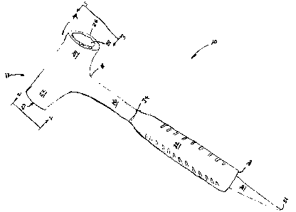
Fig. 1 is a perspective view of the combination tool;
Fig. 2 is a plan view of the hammer head of the combination tool along line 2-
2 of
Fig. 1;
Fig. 3 is a plan view of the wrench head of the combination tool along line 3-
3 of
Fig. 1; and
Fig. 4 is a plan view of the tool of Fig. 1 in operation.
3

CA 02665571 2009-05-06
DESCRIPTION OF THE PREFERRED EMBODIMENT
OF THE INVENTION
Referring to Fig. 1, a combination tool 10 with a hammer portion 12 and a
wrench
portion 14 is depicted. The tool 10 includes an elongated handle 16 having a
first
18 and a second end 20. A hammer head 22 is formed substantially
perpendicularly and extending from the first end 18 of the elongated handle
16.
A wrench head in the form of a circumferential wrench wall 24 is also formed
substantially perpendicularly and extending from the first end 18 of the
elongated
handle 16 but is also formed substantially longitudinally and extending away
from
the hammer head 22. Thus, the hammer head 22 and wrench wall 24 are
substantially aligned with one another and sit atop of the first end 18 of the
elongated handle 16.
As with conventional hammers, forming the wrench wall 24 opposed to and in
alignment with the hammer head 22, balances the tool 10 when a user uses the
hammer head 22, as the wrench wall 24 acts as a counterbalance. To further
balance the tool 10, the distance the hammer head 22 extends from the first
end
18 of the elongated handle 16 is substantially equal to the distance the
wrench
wall 24 extends from the first end 18 of the elongated handle 16.
As those skilled in the art will appreciate the shape of the hammer head 22
may
be any suitable hammer shape with a pounding surface 23. As shown in Fig. 2,
preferably for ease of production, the hammer head 22 is cylindrically shaped
to
match the wrench wall 22 so that the both are substantially equal in diameter.
Referring to Fig. 3, the wrench wall 24 includes an outer wall surface 26 and
an
inner wall surface 28. The inner wall surface 28 has a cross-sectional
perimeter
shaped to define a bolt head pattern. As those skilled in the art will
appreciate,
any bolt head pattern will do. To match with common excavator bolts, the cross-
sectional perimeter of inner wall surface 28 has preferably a hexagonal bolt
4

CA 02665571 2009-05-06
pattern with a 1 1/2" drive. The thickness "t" of the wrench wall varies
around the
wrench head wall 24 and as those skilled in the art will appreciate can be any
thickness suitable to withstand wrenching forces.
Referring back to Fig. 1, the tool 10 further includes a pin bar 30 formed
substantially longitudinally and extending from the second end 20 of the
elongated handle 16. The pin bar 30 may be any suitable shape connected to
the second end 20 but tapers to a point 31 so that it can be used as a
scraping
tool.
To dampen the vibrations experienced by the tool during its use as a hammer
and to provide a user with a gripping surface, a rubber sleeve 32 may be
included to encase the elongated handle 16. As those skilled in art will
appreciate, the length of the rubber sleeve 32 may be of any length, but
preferably it encases the elongated handle 16 from the second end 20 to
substantially a mid-point 34 of the elongated handle 16.
As those skilled in the art will also appreciate, the cross-sectional shape of
the
handle 16 may be any suitable shape, but is preferably substantially
circularly
shaped from the first end 18 to the mid-point 34 of the handle 16 and then
substantially ovally shaped from the mid-point 34 to the second end 20.
For safety and to increase the tool's 10 visibility while in use in the field,
the
elongated handle 16, hammer head 22, and wrench wall 24 may be painted
orange. Additionally, if need be the pin bar 30 may also be painted orange.
For ease of production, the elongated handle 16, hammer head 22, wrench wall
24 and pin bar 30 may all be formed from a unitary material, such as steel. As
those skilled in the art will appreciate any suitable material may be used.
5

CA 02665571 2009-05-06
As depicted in Fig. 4, to provide clearance for the handle 16 from an object
"0" in
its path of movement when the tool 10 is being used to wrench a bolt "B", the
wrench head wall 24 may be offset from the handle. As such, the inside angle
"a" between the circumferential wrench wall 24 and the elongated handle 16 can
range between 900 and 105 .
It will thus be seen that a new and novel combination tool with hammer and
wrench heads has been illustrated and described and it will be apparent to
those
skilled in the art that various changes and modifications may be made therein
without departing from the spirit of the invention.
6

Dessin représentatif
Une figure unique qui représente un dessin illustrant l'invention.
États administratifs

2024-08-01 : Dans le cadre de la transition vers les Brevets de nouvelle génération (BNG), la base de données sur les brevets canadiens (BDBC) contient désormais un Historique d'événement plus détaillé, qui reproduit le Journal des événements de notre nouvelle solution interne.

Veuillez noter que les événements débutant par « Inactive : » se réfèrent à des événements qui ne sont plus utilisés dans notre nouvelle solution interne.

Pour une meilleure compréhension de l'état de la demande ou brevet qui figure sur cette page, la rubrique Mise en garde , et les descriptions de Brevet , Historique d'événement , Taxes périodiques et Historique des paiements devraient être consultées.

Historique d'événement

Description Date
Inactive : Morte - Aucune rép. dem. par.30(2) Règles 2016-11-04
Demande non rétablie avant l'échéance 2016-11-04
Réputée abandonnée - omission de répondre à un avis sur les taxes pour le maintien en état 2016-05-06
Inactive : Abandon. - Aucune rép dem par.30(2) Règles 2015-11-04
Inactive : Dem. de l'examinateur par.30(2) Règles 2015-05-04
Inactive : Rapport - CQ réussi 2015-04-30
Lettre envoyée 2014-05-06
Requête d'examen reçue 2014-04-25
Toutes les exigences pour l'examen - jugée conforme 2014-04-25
Exigences pour une requête d'examen - jugée conforme 2014-04-25
Demande publiée (accessible au public) 2010-11-06
Inactive : Page couverture publiée 2010-11-05
Inactive : CIB attribuée 2009-08-25
Inactive : CIB en 1re position 2009-08-25
Inactive : CIB attribuée 2009-08-25
Inactive : Certificat de dépôt - Sans RE (Anglais) 2009-06-03
Demande reçue - nationale ordinaire 2009-06-03
Déclaration du statut de petite entité jugée conforme 2009-05-06

Historique d'abandonnement

Date d'abandonnement Raison Date de rétablissement
2016-05-06

Taxes périodiques

Le dernier paiement a été reçu le 2015-04-07

Avis : Si le paiement en totalité n'a pas été reçu au plus tard à la date indiquée, une taxe supplémentaire peut être imposée, soit une des taxes suivantes :

  • taxe de rétablissement ;
  • taxe pour paiement en souffrance ; ou
  • taxe additionnelle pour le renversement d'une péremption réputée.

Les taxes sur les brevets sont ajustées au 1er janvier de chaque année. Les montants ci-dessus sont les montants actuels s'ils sont reçus au plus tard le 31 décembre de l'année en cours.
Veuillez vous référer à la page web des taxes sur les brevets de l'OPIC pour voir tous les montants actuels des taxes.

Historique des taxes

Type de taxes Anniversaire Échéance Date payée
Taxe pour le dépôt - petite 2009-05-06
TM (demande, 2e anniv.) - petite 02 2011-05-06 2011-04-29
TM (demande, 3e anniv.) - petite 03 2012-05-07 2012-05-03
TM (demande, 4e anniv.) - petite 04 2013-05-06 2013-05-04
TM (demande, 5e anniv.) - petite 05 2014-05-06 2014-04-25
Requête d'examen - petite 2014-04-25
TM (demande, 6e anniv.) - petite 06 2015-05-06 2015-04-07
Titulaires au dossier

Les titulaires actuels et antérieures au dossier sont affichés en ordre alphabétique.

Titulaires actuels au dossier
URSUS MORITZ
Titulaires antérieures au dossier
S.O.
Les propriétaires antérieurs qui ne figurent pas dans la liste des « Propriétaires au dossier » apparaîtront dans d'autres documents au dossier.
Documents

Pour visionner les fichiers sélectionnés, entrer le code reCAPTCHA :


Pour visualiser une image, cliquer sur un lien dans la colonne description du document. Pour télécharger l'image (les images), cliquer l'une ou plusieurs cases à cocher dans la première colonne et ensuite cliquer sur le bouton "Télécharger sélection en format PDF (archive Zip)" ou le bouton "Télécharger sélection (en un fichier PDF fusionné)".

Liste des documents de brevet publiés et non publiés sur la BDBC .

Si vous avez des difficultés à accéder au contenu, veuillez communiquer avec le Centre de services à la clientèle au 1-866-997-1936, ou envoyer un courriel au Centre de service à la clientèle de l'OPIC.


Description du
Document 
Date
(aaaa-mm-jj) 
Nombre de pages   Taille de l'image (Ko) 
Abrégé 2009-05-05 1 18
Description 2009-05-05 6 199
Revendications 2009-05-05 2 58
Dessins 2009-05-05 3 33
Dessin représentatif 2010-10-11 1 7
Certificat de dépôt (anglais) 2009-06-02 1 156
Rappel de taxe de maintien due 2011-01-09 1 114
Rappel - requête d'examen 2014-01-06 1 117
Accusé de réception de la requête d'examen 2014-05-05 1 175
Courtoisie - Lettre d'abandon (taxe de maintien en état) 2016-06-16 1 171
Courtoisie - Lettre d'abandon (R30(2)) 2015-12-15 1 165
Taxes 2012-05-02 1 155
Taxes 2013-05-03 1 155
Correspondance 2009-06-02 1 55
Correspondance 2011-01-09 1 38
Taxes 2011-04-28 1 201
Taxes 2014-04-24 1 23
Taxes 2015-04-06 1 24