Note : Les descriptions sont présentées dans la langue officielle dans laquelle elles ont été soumises.
CA 02666820 2009-05-26
ATTORNEY DOCKET NO. PATENT
CTSI-PO07US
TRAILER WITH ADJUSTABLE GROUND CLEARANCE
BACKGROUND OF THE INVENTION
FIELD OF THE INVENTION
[0001] The present invention relates to a method and apparatus for selectably
adjusting the ground clearance of a towed trailer vehicle.
DESCRIPTION OF THE RELATED ART
[0002] Whenever, a trailer transports a high load it must minimize its load
height
to avoid the need for special routing or for hiring an escort as may be
necessitated by
local or state regulations. This problem is especially acute for the long
trailers used for
hauling oilfield equipment such as coiled tubing rigs used for well drilling
and servicing.
Coiled tubing rigs normally are rather tall, and the desirability of mounting
an entire rig
on a single trailer leads to the use of long trailers.
[0003] Further complicating this problem is the fact that many well locations
are
only accessible over very rough, uneven roads. Pulling long, low trailers
loaded with
heavy equipment over rough, uneven roads often leads to problems in
expeditiously
getting the oilfield equipment to a well site. This is particularly true, if
it is desired to
deliver the coiled tubing rigs to the well site on a single trailer.
[0004] A need exists for a simple, inexpensive means of adjusting trailer
ground
clearance which is easy to use.
SUMMARY OF THE INVENTION
[0005] This invention pertains to a device for adjusting the ground clearance
of a
trailer. One embodiment of the present invention includes a simple mechanical
means for
selectably and reversibly increasing the ground clearance of a trailer so that
it can operate
within a safe overall height limit when operating on improved roads, but can
also operate
with increased ground clearance on uneven roads.
1
CA 02666820 2009-05-26
r
ATTORNEY DOCKET NO. PATENT
CTSI-P007US
[0006] One embodiment of the present invention includes a vehicle trailer
comprising: (a) a rear deck; (b) a forward deck having a second end; (c) a
central deck
having a front end and a rear end, wherein the rear end is attached to the
rear deck; and d)
a pivotable altitude adjustment mechanism connecting the front end of the
central deck to
the second end of the forward deck, wherein the altitude adjustment mechanism
includes
a plurality of selectably engageable pin connections; whereby the forward deck
and the
central deck have a unique angular alignment with each other for each pin
connection.
[0007] A second embodiment of the present invention includes a vehicle trailer
comprising: (a) a rear deck; (b) a forward deck having a first end and a
second end; (c) a
central deck having a front end and a rear end, wherein the rear end is
attached to the rear
deck; and (d) a pair of pivotable altitude adjustment mechanisms connecting
the front end
of the central deck to the second end of the forward deck, wherein each
altitude
adjustment mechanism includes (i) a pair of rear pivot plates mounted on the
front end of
the central deck parallel to and offset from a longitudinal midplane of the
trailer, wherein
each rear pivot plate has a pivot hole and a plurality of position locking pin
holes, (ii) a
forward pivot plate mounted on the second end of the forward deck parallel to
and offset
from the longitudinal midplane of the trailer, wherein the forward pivot plate
has a pivot
hole and a plurality of position locking pin holes, and (iii) a pivot pin
connecting the
pivot hole of the forward pivot plate to the pivot holes of the pair of rear
pivot plates
when the pivot holes of the forward pivot plate and the rear pivot plates are
coaxially
aligned, and (iv) a selectably engageable position locking pin connecting one
of a
plurality of coaxially aligned position locking pin hole sets, wherein each
set of position
locking pin holes includes one position locking pin hole of the forward pivot
plate and
one position locking pin hole in each rear pivot plate, and whereby each set
of position
locking pin holes is associated with a particular height of ground clearance
for the front
end of the central deck.
2
CA 02666820 2009-05-26
ATTORNEY DOCKET NO. PATENT
CTSI-P007US
[0008] Another embodiment of the present invention includes a vehicle trailer
comprising: (a) a rear deck; (b) a forward deck having a first end and a
second end; (c) a
central deck having a front end and a rear end, wherein the rear end is
attached to the rear
deck; and (d) a pair of pivotable altitude adjustment mechanisms connecting
the front end
of the central deck to the second end of the forward deck, wherein each
altitude
adjustment mechanism includes (i) a first rear pivot plate having a first
pivot hole and a
plurality of position locking pin holes, wherein the first rear pivot plate is
mounted on the
front end of the central deck parallel to and offset from the longitudinal
midplane of the
trailer, (ii) a second rear pivot plate having a second pivot hole and a
plurality of position
locking pin holes, wherein the second rear pivot plate is mounted on the front
end of the
central deck parallel to the first rear pivot plate and offset from the first
rear pivot plate
towards the longitudinal midplane of the trailer, (iii) a forward pivot plate
mounted on the
second end of the forward deck parallel to and offset from the longitudinal
midplane of
the trailer, wherein the forward pivot plate has a pivot hole and a plurality
of position
locking pin holes, and (iv) a pivot pin connecting the pivot hole of the
forward pivot plate
to the pivot holes of the pair of rear pivot plates when the forward pivot
plate is
positioned between the first and second rear pivot plates and the pivot holes
of the rear
pivot plates are coaxially aligned with the pivot hole of the forward pivot
plate, and (v) a
selectably engageable position locking pin connecting one of a plurality of
coaxially
aligned position locking pin hole sets, wherein each set of position locking
pin holes
includes one position locking pin hole of the forward pivot plate and one
position locking
pin hole in each rear pivot plate, and whereby each set of position locking
pin holes is
associated with a particular ground clearance for the front end of the central
deck.
[0009] The foregoing has outlined rather broadly several aspects of the
present
invention in order that the detailed description of the invention that follows
may be better
understood and thus is not intended to narrow or limit in any manner the
appended claims
which define the invention. Additional features and advantages of the
invention will be
3
CA 02666820 2009-05-26
ATTORNEY DOCKET NO. PATENT
CTSI-PO07US
described hereinafter which form the subject of the claims of the invention.
It should be
appreciated by those skilled in the art that the conception and the specific
embodiment
disclosed may be readily utilized as a basis for modifying or designing of the
structures
for carrying out the same purposes as the invention. It should be realized by
those skilled
in the art that such equivalent constructions do not depart from the spirit
and scope of the
invention as set forth in the appended claims.
BRIEF DESCRIPTION OF THE DRAWINGS
[0010] For a more complete understanding of the present invention, and the
advantages thereof, reference is now made to the following descriptions taken
in
conjunction with the accompanying drawings, in which:
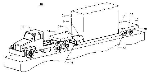
[0011] FIGURE 1 is an oblique view of a tractor-trailer combination, wherein
the
trailer having an altitude adjustment mechanism for adjusting its ground
clearance.
[0012] FIGURE 2 is a side profile view of the tractor-trailer combination of
Figure 1, showing the trailer in its first configuration for being towed on a
highway.
[0013] FIGURE 3 corresponds to Figures 1 and 2, but shows the jacks located
toward the forward deck of the trailer extended to contact the roadway
surface.
[0014] FIGURE 4 is an exploded oblique view from the forward side of the
underside of the forward deck of the trailer showing the components of the
altitude
adjustment mechanism.
[0015] FIGURE 5 is an exploded oblique view from above of the rearward side of
the forward deck of the trailer showing the same components of the altitude
adjustment
mechanism as shown in Figure 4.
[0016] FIGURE 6 corresponds to Figures 2 and 3, but with the position locking
pins having been moved to engagement with a second set of locking pin holes
after the
jacks have elevated the forward deck of the trailer sufficiently in order to
align the second
set of locking pin holes.
4
CA 02666820 2009-05-26
ATTORNEY DOCKET NO. PATENT
CTSI-PO07US
[0017] FIGURE 7 corresponds to Figure 6, but with the jacks retracted so the
trailer can be moved without interference with the roadway.
[0018] FIGURE 8 is a detail side view of the outer rear pivot plate, wherein
the
angular relationships of the position locking pin holes are indicated.
[0019] FIGURE 9 is a detail side view of the forward pivot plate, wherein the
angular relationships of the position locking pin holes are indicated.
DESCRIPTION OF THE PREFERRED EMBODIMENTS
[0020] As a note, the use of the terms "invention", "present invention" and
variations thereof throughout the subject patent application (and headings
therein) are
intended to refer or relate to one or more embodiments of the present
application, not
necessarily every embodiment or claim of the application.
[0021] Referring now to the drawings, it is noted that like reference
characters
designate like or similar parts throughout the drawings. The figures, or
drawings, are not
intended to be to scale. For example, purely for the sake of greater clarity
in the
drawings, wall thicknesses and spacings are not dimensioned as they actually
exist in the
assembled embodiments.
[0022] The present invention pertains to a device for adjusting the ground
clearance of a trailer. One embodiment of the present invention includes a
simple
mechanical means for selectably and reversibly increasing the ground clearance
of a
trailer so that it can operate within a safe overall height limit when
operating on improved
roads, but can also operate with increased ground clearance on uneven roads.
[0023] The materials of construction of the structural components of the
height
adjustment mechanism are typically those employed by other commercial highway
vehicles. The tractor is generally a heavy duty commercially available vehicle
which has
a fifth wheel for towing a trailer and multiple rear axles. The tractor
normally will have a
steel frame and either a steel or fiberglass cab.
5
CA 02666820 2009-05-26
ATTORNEY DOCKET NO. PATENT
CTSI-P007US
[0024] For hauling high loads, the trailer will preferably be a "low-boy"
trailer
with a depressed center section for carrying cargo at a lower height than
would a standard
trailer with a flat deck. The trailer normally is fabricated from steel
because of the high
weight and long span between its pivot pin and its multiple rear axles,
although
aluminum can be used for many parts in order to minimize vehicle weight. The
trailer is
provided with a pair of either hydraulic or mechanical jacks having foot
plates for
contacting the ground. The jacks are mounted at or near the forward and back
ends of the
depressed center section of the trailer.
[0025] Referring to Figure 1, a tractor/trailer rig 10 utilizing the low-boy
trailer
20 is shown in an oblique view hauling a tall rectangular load 70. The tractor
11 is a
heavy duty commercially available vehicle having a fifth wheel 12 for towing
the trailer
and multiple driven rear axles. The load 70 is shown as a rectangular prism
for
simplicity, but can have a wide variety of configurations, depending upon the
make-up
and desired use of the load.
15 [0026] For example, when designing a trailer for mounting a coiled tubing
rig for
use in well drilling or servicing, the rig designer will normally make the
reel for the
tubing and the other rig components as large as possible to still be
compatible with
standard unpermitted vehicle height limits. This is done in order to permit
using larger
diameter tubing or more tubing on the reel or both.
20 [0027] Figure 2 shows a side profile view of the tractor 11 and trailer 20
of the
present invention, wherein the trailer is in its lower first transit position,
or highway
towing position, suitable for unpermitted highway use. The highway ground
clearance
for the trailer of Figure 2 is preselected by the trailer designer to be the
minimum
compatible with most paved roads, so that the practical load height can be
maximized.
However, the ground clearance of the trailer 20 as shown in Figure 2 is
insufficient for
rough roads.
6
CA 02666820 2009-05-26
ATTORNEY DOCKET NO. PATENT
CTSI-P007US
[0028] Referring to both Figures 1 and 2, the trailer 20 is seen to have a
rear deck
51 which is necessarily elevated in order to provide clearance for the rear
axle assemblies
52. The rear deck 51 is flat and typically has a width of approximately 8
feet, while its
length is generally somewhat longer in order to accommodate multiple rear axle
assemblies. The rear axle assemblies include the axles, brakes, conventional
spring
supported suspensions, shock absorbers, wheels, and tires common to most
conventional
heavy duty trailers suitable for both highway and unimproved road use. The
flat upper
surface of the rear deck 51 is underlain and supported by longitudinal beams
with smaller
transverse cross beams (not shown). When in the highway towing configuration
shown
in Figure 2, the rear deck 51 is substantially parallel to the approximately
planar roadway
80 supporting the tractor-trailer rig 10.
[0029] The rectangular main or central deck 21 of the low-boy trailer 20 has
the
same width as that of the rear deck 51 and is structurally connected to the
rear deck by a
short inclined deck segment which slopes downwardly in the forward direction.
The
central deck 21 is elongated and serves as the main load supporting area for
the trailer 20.
When unloaded, the central deck 21 is generally cambered upwardly in its
center.
However, when the central deck 21 is statically loaded with its design load
cargo 70, the
upper surface of the central deck is substantially planar.
[0030] Both the central deck 21 and the short inclined deck segment are
connected to the rear deck 51 by continuous longitudinal beams to support the
large
bending loads associated with supporting the cargo on the central deck.
Transverse cross
beams are used to further stiffen and strengthen the deck surface of the
central deck 21,
similar to the rear deck 51. When in the highway towing configuration shown in
Figure
2, the main bed 21 of the trailer 20 is substantially parallel to the rear
deck 51.
[0031] An altitude adjustment mechanism 24 is used to join the central deck 21
to
the forward deck 54 of the trailer 20. Figures 4 and 5 show exploded views of
the
altitude adjustment mechanism 24. A pair of altitude adjustment mechanisms 24
are
7
CA 02666820 2009-05-26
ATTORNEY DOCKET NO. PATENT
CTSI-PO07US
utilized to selectably adjust the ground clearance of the front end of the
central deck 21 of
the trailer, with one altitude adjustment mechanism 24 mounted on each side of
the trailer
20. The two altitude adjustment mechanisms 24 are symmetrical mounted about
the
longitudinal midplane of the trailer 20.
[0032] Each altitude adjustment mechanism 24 includes three principle
components. One pair of elements (the rear pivot plates 25 and 30) of the
altitude
adjustment mechanism 24 is attached to the forward end of the central deck 21,
while the
other element (the forward pivot plate) of the mechanism 24 is attached to the
rear side of
the forward deck 54 of the trailer 20.
[0033] The two elements of each altitude adjustment mechanism 24 mounted on
the forward end of the central deck 21 of the trailer 20 are a pair of
substantially similar
rear pivot plates 25 and 30. The outboard or outer pivot plate 25 is mounted
vertically
with its outer side flush with the side of the main bed of the central deck
21. The inboard
or inner pivot plate 30 of each rear pivot plate pair is mounted vertically
and aligned
parallel to the outboard pivot plate 25. Each inboard pivot plate 30 is spaced
apart from
its adjacent outboard pivot plate 25 in the direction towards the trailer
longitudinal
midplane.
[0034] Referring to Figure 8, it can be seen that each rear outboard pivot
plate 25,
and similarly each rear inboard pivot plate 30, consists of an approximately
9d arcuate
sector of a circle with a projecting tab on its lower horizontal straight
side. Going
counterclockwise from its righthand lower side as seen in Figures 5 and 8, the
perimeter
of each pivot plate 25 and 30 has a short first vertical edge 61, a 9(?
arcuate edge 62
curving upwardly and to the left, a short first horizontal edge 63, and a long
vertical edge
64. The short first horizontal edge 63 and the long vertical edge 64 are
joined by a small
radius arc.
[0035] Adjoining the long vertical edge 64 on its lower end is a short edge 65
inclined at approximately 4:!' from the vertical to slope downwardly toward
the front
8
CA 02666820 2009-05-26
ATTORNEY DOCKET NO. PATENT
CTSI-P007US
portion of the central deck 21 to which the outboard pivot plate 25 is
attached. Adjoining
the inclined edge 65 is a second vertical edge 66 having a length equal to the
vertical
thickness of the central deck 21. A long horizontal edge 67 extends from the
second
vertical edge 66 to the lower end of the first vertical edge 61.
[0036] The center of the 9d are edge 62 lies in the plane of the second
vertical
edge 66. Each of the rear outboard 25 and inner 30 pivot plates is attached by
welding to
both the forward deck and the upper surface of the central deck 21 of the
trailer 20. The
rear pivot plates 25 and 30 are strongly and rigidly connected to the
structure underneath
the upper load bearing surface of the central deck 21 of the trailer 20. In
particular,
loadings are efficiently transferred between the rear pivot plates 25 and 30
and the
longitudinal beams supporting the main bed of the central deck 21 of the
trailer.
[0037] A large diameter pivot pin through hole 26 is aligned with the axis of
the
arcuate edge 62 of the outer pivot plates 25. A corresponding large diameter
pivot pin
through hole 31 is aligned with the axis of the arcuate edge 62 of the inner
pivot plates 30
and is coaxial with the through hole 26 of the outer pivot plate 25.
[0038] For the rear outer pivot plates 25, a first position locking pin hole
27 is
located vertically at radius R above the pivot pin hole 26. A second position
locking pin
hole 28 is located, clockwise from hole 27 by angle 'DA, at radius R from the
pivot pin
hole 26. The first position locking pin hole 27 and second position locking
pin hole 28
have substantially the same diameter, which is smaller than that of the pivot
pin hole 26.
The pivot pin hole 26 and the position locking pin holes 27 and 28 are
mutually parallel
and normal to the longitudinal midplane of the trailer 20.
[0039] For the rear inner pivot plates 30, a first position locking pin hole
32 is
located vertically at radius R above the pivot pin hole 31, and a second
position locking
pin hole 33 is located at radius R from the pivot pin hole 31 clockwise from
hole 32 by
angle (DA. The first 32 and second 33 position locking pin holes have the same
diameter
which is smaller than that of the pivot pin holes 31. The pivot pin hole 31
and the
9
CA 02666820 2009-05-26
ATTORNEY DOCKET NO. PATENT
CTSI-P007US
position locking pin holes 32 and 33 are mutually parallel and normal to the
longitudinal
midplane of the trailer 20. In addition, the first position locking pin hole
27 and the
second position locking pin hole 28 of the outboard pivot plate 25 are coaxial
with the
corresponding first position locking pin hole 32 and the second position
locking pin hole
33 of the inner pivot plates 30.
[0040] A pair of hydraulic jacks 44 is located at the forward end of the
central
deck 21 of the trailer 20. The jacks 44 typically utilize conventional
hydraulic double
acting single end cylinders with the cylinders oriented perpendicular to the
flat deck of
the central deck 21 of the trailer 20. The selectably reciprocable rods of the
jacks 44
extend downwardly. The jacks 44 are similar to each other and generally
consist of a
conventional hollow right circular cylindrical body of revolution 45 having a
main bore
diameter, a blind end at an upper end, and a reduced bore diameter gland at
the lower
end.
[0041] Each jack body 45 has a radially outwardly extending cylinder mounting
bracket 46 on one side. A right circular cylindrical jack cylinder rod 47
having an upset
transverse cylindrical piston head at its upper end and a male threaded distal
portion at its
lower end is deployed in the cylinder body 45. The piston head and the rod
shank
respectively seal to the main bore and the gland of the cylinder body. A foot
plate
assembly 48 having from its upper end a female socket threadedly engaged with
the male
thread of the rod 47, a pivoting hinge with a foot plate pivot pin 49, and a
rectangular
transverse foot plate is located at the bottom of each jack 44. The axis of
the foot plate
pivot pin 49 is horizontal and is perpendicular to the longitudinal midplane
of the trailer
20.
[0042] Each jack 44 is attached to a rear inner pivot plate 30 in its vertical
position inboard of and extending forward of the forward vertical edge of the
inner pivot
plate 30. The positioning of the jacks 44 is such that their foot plates will
not interfere
CA 02666820 2009-05-26
ATTORNEY DOCKET NO. PATENT
CTSI-P007US
with the forward deck of the central deck 21 of the trailer 20 when the foot
plates 48 of
the jacks are raised or lowered.
[0043] The forward deck 54 of the trailer 20 is a short flat section which is
somewhat narrower than the rest of the trailer. The forward deck 54 of the
trailer has a
conventional kingpin extending downwardly on the underside of the forward
deck. The
kingpin 55 attachment is transverse to the upper surface of the forward deck
and is
located on the longitudinal midplane of the trailer 20 near the forward deck
of the
forward deck. The kingpin 55 is configured to be selectably latched and
unlatched from
the fifth wheel 12 of the tractor 11 so that the trailer 20 can be towed
readily. The nature
of the kingpin 55 to fifth wheel 12 attachment is such that it can tolerate a
reasonably
large amount of angular misalignment while still transmitting towing and
braking forces
between the trailer 20 and the tractor 11. The kingpin 55 and the upper
surface of the
forward deck 54 are structurally interconnected by large longitudinal beams
and smaller
transverse beams.
[0044] Towards its rear end, the forward deck 54 is connected there to a pair
of
identical forward pivot plates 56. One forward pivot plate 56 is attached by
lapping
welding the pivot plate 56 onto each outboard side of the forward deck 54. As
can be
seen in Figures 4, 5, and 9, the forward pivot plates 56 extend to the rear
and below the
main portion of the forward deck 54.
[0045] The lateral positioning of the pivot plates 25, 30, and 56 relative to
the
longitudinal centerline of the trailer 20 is such that each forward pivot
plate 56 of the
forward deck 54 will have a loose slip fit between a rear outboard pivot plate
25 and a
rear inboard pivot plate 30 of the central deck 21 when the two portions of
the trailer are
comated with their pivot holes 26, 31, and 57 placed in a coaxial position and
the
longitudinal centerlines of the forward deck 54 and the central deck 21 of the
trailer
aligned.
11
CA 02666820 2009-05-26
ATTORNEY DOCKET NO. PATENT
CTSI-P007US
[0046] Referring to Figure 9, the configuration of the forward pivot plates 56
is as
follows moving counterclockwise from the lower rear corner of the plates. Edge
84 is an
arcuate surface extending upwardly and a forward direction and covering an arc
length of
more than 90'. The upper end of the arcuate edge 84 is located vertically
above the axis
of the arcuate surface. Horizontal edge 85 is coplanar with the upper deck
surface of the
forward deck 54 and extends forward past the rear transverse end of the
forward deck
surface. Vertical edge 86 extends from the upper side to the lower side of the
forward
deck 54. First inclined edge 87 slopes downwardly in a rearward direction,
where it
intersects second inclined edge 88.
[0047] The second inclined edge 88 slopes slightly upwardly in the rearward
direction until it intersects the arcuate edge 84. The intersection of the
first 87 and
second 88 inclined edges is radiused, as is the intersection of the second
inclined edge 88
and the arcuate edge 84. Typically rectangular and triangular plate segments
are used to
form hollow triangular prismatic transitions between the vertical edges 86 of
the two
forward pivot plates 56 and the sides of the forward deck 54.
[0048] A large diameter pivot pin through hole 57 is aligned with the axis of
the
arcuate edge 84 of the forward pivot plates 56. The diameter of the pivot pin
holes 57 in
the forward pin plates is substantially the same as that of the pivot pin
holes 26 and 31 of
the rear outer 25 and rear inner 30 pivot plates.
[0049] Refering to Figure 9, a first position locking pin hole 58 in the
forward
pivot plate 56 is located vertically at radius R above the pivot pin hole 57,
and a second
position locking pin hole 59 is located at radius R from the pivot pin hole 57
clockwise
from position locking pin hole 58 by angle bB. The first 58 and second 59
position
locking pin holes of the forward pivot plate 56 have about the same diameter
as that of
the position locking pin holes 27, 28 of the rear outer pivot plates 25 and
the position
locking pin holes 32, 33 of the rear inner pivot plates 30.
12
CA 02666820 2009-05-26
ATTORNEY DOCKET NO. PATENT
CTSI-P007US
[0050] At assembly, the forward pivot plate 56 is positioned between the rear
pivot plates 25 and 30 with the pivot pin holes 26, 31, and 57 coaxially
aligned and
normal to the longitudinal midplane of the trailer 20. Furthermore, the first
position
locking pin holes 25 and 32 of the rear pivot plates 25 and 30 are coaxially
aligned with
the first position locking pin hole 58 of the forward pivot plate 56, and the
second
position locking pin holes 28 and 33 of the rear pivot plates 25 and 30 are
coaxially
aligned with the second position locking pin hole 59 of the forward pivot
plate 56.
[0051] Two pivot pins 36 and two position locking pins 38 are used to join the
elements of the two altitude adjustment mechanisms 24 and thus the forward
deck 54 to
the central deck 21 of the trailer 20. The pivot pins 36 are headed on a first
end and
generally have a slight taper on the second end. The length of the right
circular
cylindrical central portion of the pivot pins 36 is sufficient to extend
through and
approximately one inch beyond each set of three interleaved pivot plates 25,
30, 56, and
the diameter of the pivot pins 36 is such that they are a slip fit to the
pivot pin holes 26,
31, and 57.
[0052] Typically, transverse diametrical keeper pins holes 40 are offset
axially
outwardly from the head of the pivot pins 36. The pivot pins 36 are stabbed
through the
coaxial pivot pin holes 26, 57, and 31 at assembly of the trailer 20 so that
the transverse
inner shoulders of the headed pivot pins 36 abut a rear outboard pivot plate
surface.
Headed elongated cylindrical pivot pin keepers 37 are inserted through the
keeper pin
holes 40 to retain the pivot pins 36 in place after assembly. Often headed
bolts with lock
nuts are used for this purpose. Following the insertion of the pivot pins and
their keepers
37, the central deck section 21 and the forward deck section 54 of the trailer
20 are
hinged together on a horizontal axis transverse to the longitudinal midplane
of the trailer.
[0053] The two position locking pins 38 are substantially similar to the pivot
pins
36, with the exception that the diameter of the central cylindrical section of
the position
locking pins 38 is a slip fit both to the first position locking pin holes 27,
32, 58 and the
13
CA 02666820 2009-05-26
ATTORNEY DOCKET NO. PATENT
CTSI-P007US
second position locking pin holes 28, 33, 59 position locking pin holes.
Position locking
pin keepers 39, used for the position locking pins 38, are similar to the
keeper pins 37
used with the pivot pins 36 with the exception that the keeper pins 39 are
shorter, since
the diameter of the position locking, pins 38 is less than that of the pivot
pins 36. The
position locking pin keepers 39 are inserted into diametrical cross holes 41
in the exposed
nonheaded ends of the position locking pins 38 to provide pin retention.
[0054] When the trailer has both its pivot pins 36 installed as described
above and
its position locking pins 38 installed in either the coaxial position locking
pin holes 27,
32, 58 or the coaxial position locking pin holes 28, 33, 59, the trailer 20
has its central
deck section 21 structurally attached in a rigid and safe load bearing
configuration.
Either of the two described configurations is structurally competent to
transport a heavy
trailer cargo 70 on both highways and unimproved roads.
[0055] OPERATION OF THE INVENTION
[0056] To complete assembly of the trailer 20, the position locking pins 38
with
their position locking pin keepers 39 are installed in either the coaxial
position locking
pin holes 27, 32, and 58 or alternatively in the coaxial position locking pin
holes 28, 33,
and 59. For the purpose of example, it is assumed herein that the position
locking pins
are preinstalled in the coaxial first position locking pin holes 27 and 32 of
the central
deck portion 21 and the mutually coaxial first position locking pin holes 58
of the
forward deck 54 portion of the trailer 20. The result is the first
configuration of the trailer
20 shown in both Figures 1 and 2, with the jacks 44 fully retracted. This
first
configuration of the trailer 20 provides both an acceptable road clearance and
a minimal
practical load height for highway use.
[0057] In order to increase the road clearance for the trailer 20 from that
shown in
Figures 1 and 2, the first step is to extend the jacks 44 until they bear
fully on the surface
of the roadway, as is shown in Figure 3. When the jacks 44 are then extended
14
CA 02666820 2009-05-26
ATTORNEY DOCKET NO. PATENT
CTSI-P007US
sufficiently further, the transverse loadings on the position locking pins 38
are reduced
sufficiently to permit their extraction after the removal of the position
locking pin keepers
39. Following extraction of the position locking pins 38, the jacks are
extended still
further until the second position locking pin holes 28, 33, and 59 are brought
into axial
alignment, as shown in Figure 6.
[0058] The change of alignment from the first position shown in Figures 1 and
2
to that of Figure 6 is effected by elevating both the forward deck of the
central deck 21
and the rear portion of the forward deck 54, which are still pinned together
by the pivot
pins 36. At this point, the position locking pins 38 are then fully inserted
into the now
aligned and coaxial second position locking pin holes 28, 33, 59 and
individually retained
by their respective position locking pin keepers 39 engaged in the holes 41 of
the locking
pins 38. The position locking pins 38 are shown in their installed second
position in
Figure 6.
[0059] To transition from the arrangement shown in Figure 6 to the completed
off-highway position shown in Figure 7 all that is necessary is to fully
retract the jacks 44
so that they do not extend below the bottom of the central deck 21 of the
trailer 20.
When the trailer is elevated as is shown in Figure 7, the center portion of
the length of the
trailer 20 located between the fifth wheel 12 and the rear axles 52 is
sufficiently elevated
that it will clear high spots on most unimproved roads. The resulting improved
road
clearance allows the low boy trailer to be brought into and removed from the
majority of
most remote field locations.
[0060] Adjusting the trailer from the higher ground clearance configuration to
the
lower ground clearance configuration, the operator reverses the procedure for
transitioning from the low ground clearance configuration of Figure 2 to the
improved
ground clearance configuration of Figure 7.
CA 02666820 2009-05-26
ATTORNEY DOCKET NO. PATENT
CTSI-PO07US
[0061] ADVANTAGES OF THE INVENTION
[0062] The provision of the selectably lockable articulated transverse axis
joint
intermediate to the length of the low boy trailer of the present invention
readily permits
adjusting the ground clearance of the trailer to handle different road
conditions. The
selectable locking of the altitude adjustment mechanism 24 is accomplished
easily with
the use of the position locking pins 38.
[0063] Fabrication costs for the altitude adjustment mechanism are low. The
cost
of the simple mechanical components is relatively low, and maintenance costs
are
minimal. The pinned connection is inherently robust while providing sufficient
stiffness
and strength to ensure long term reliability. Equipment inspection is quite
simple.
[0064] Operator training is relatively simple and equipment inspection is
basic.
There are numerous advantages of being able to provide a practical maximum
load height
when operating on highways with vertical height limitations, while still being
able to
selectably and easily increase the road clearance of the critical central
section of the
trailer.
[0065] Although the present invention has been described in detail, it should
be
understood that various changes, substitutions and alterations can be made
herein without
departing from the spirit and scope of the invention as defined by the
appended claims.
As may be understood readily by those skilled in the art, certain variations
in the structure
of the present invention may be made without departing from the spirit of the
invention.
For instance, mechanical rather than hydraulic jacks could be used to raise
and lower the
trailer. The position locking pins could be made so that they can be withdrawn
and
engaged using screw threads to reciprocate the pins out of and into full
engagement with
the position locking pin holes. These and other minor changes can be made
without
departing from the spirit of the invention.
16