Note : Les descriptions sont présentées dans la langue officielle dans laquelle elles ont été soumises.
CA 02666892 2009-05-26
Construction apparatus with pivotable mast
The invention relates to a construction apparatus comprising a base carrier, a
mast which is arranged on the base carrier in a pivotable manner, a first
hydraulic
cylinder and a second hydraulic cylinder for erecting the mast, which are
connected to each other in an articulated manner in a connecting section, the
first
hydraulic cylinder being linked to the base carrier and the second hydraulic
cylinder being linked to the mast, and a coupling rocker-arm which is linked
on
one side to the mast and on the other side to the connecting section.
A generic construction apparatus is known from US 4,708,581. According to this
printed publication use is made of a generic twin-cylinder arrangement for
erecting
and folding a transfer arm which has a mast-like section. The drilling mast
proper
is erected by means of a telescopic cylinder.
Another construction apparatus with a mast, on the holder of which two
hydraulic
cylinders are arranged in series, is known from JP 05-202686 A.
JP 2002-285775 A discloses a construction apparatus, the mast of which is of
telescopic design and can be pivoted by means of a hydraulic cylinder about a
horizontal pivot axis.
The o b j e c t of the invention is to improve a generic construction
apparatus in
such a manner that a particularly high reliability and efficiency is achieved.
The object is solved in accordance with the invention by a construction
apparatus
having the features of claim 1. Preferred embodiments are stated in the
dependent claims.
CA 02666892 2009-05-26
-2-
The construction apparatus according to the invention is characterized in that
in
the part of the connecting section a spacer is arranged, through which the
connecting section is supported on the mast in a detachable manner.
In accordance with the invention two erecting cylinders coupled in series are
provided for erecting the mast, the cylinders being connected to each other
via a
coupling rocker-arm that is linked to the mast. In such an arrangement the
first
hydraulic cylinder is linked in the corner part of a triangle formed by the
second
hydraulic cylinder, the coupling rocker-arm and a mast section extending
between
the second hydraulic cylinder and the coupling rocker-arm.
The invention is based on the finding that in the case of such a cylinder
arrangement relatively high forces may have to be applied in particular at the
onset of the erecting process. The reason for this can reside in the fact that
at the
beginning of the erecting process the hydraulic cylinders, and in particular
the
second hydraulic cylinder, extend at a comparatively small angle to the
longitudinal axis of the mast. Therefore, the force vector applied by the
cylinders
extends at a small angle to the longitudinal axis of the mast so that the
force
component that acts transversely to the longitudinal axis of the mast and
therefore
in the erecting direction is correspondingly small.
A fundamental idea of the invention resides in a spacer, by means of which the
connecting section located between the second hydraulic cylinder and the
coupling rocker-arm can be supported on the mast in the starting phase of the
erecting process. The spacer allows for an additional introduction of force
from the
connecting section into the mast and can thus relieve the second hydraulic
cylinder but also the coupling rocker-arm. In particular, the spacer can be
arranged in a steep manner to the longitudinal axis of the mast, preferably it
can
be arranged at an angle of at least approximately 900 to the longitudinal axis
of
the mast so that the force vector transmitted through the spacer can be
directed at
least approximately in the erecting direction. Since there is no need for any
unnecessary force components to be applied perpendicularly to the erecting
CA 02666892 2009-05-26
-3-
direction, the forces to be applied are comparatively small and the hydraulic
cylinders are load-relieved. In particular, the hydraulic cylinders can thus
be
designed for smaller operating forces whilst having the same weight of the
mast
so that the purchasing costs are reduced.
In accordance with the invention the connecting section is supported on the
mast
in a detachable manner. Hence, the contact made via the spacer between the
connecting section and the mast can be detached, if the introduction of force
effected through the spacer into the mast is no longer required in particular
at a
late stage of the erecting process. In the simplest case, for a detachable
connection the spacer rests on the mast or on the connecting section, i.e. the
mast or the connecting section forms a stop for the spacer, which limits a
further
movement of the spacer towards the mast or the connecting section, whilst
still
permitting a detachment of the spacer through a movement away from the mast or
the connecting section. According to this embodiment the spacer is only kept
under pressure but not, however, kept under tension by the mast or the
connecting section. Basically, for a more complex force transmission a locking
device can also be provided, with which the spacer is detachably kept both
under
pressure and under tension on the mast or the connecting section.
The base carrier concerned here can be a carrier vehicle for example or a
superstructure that can be mounted in a detachable manner on a carrier
vehicle.
By preference, the base carrier has an at least approximately horizontally
extending frame. On the base carrier a rope winch for moving a drilling sledge
longitudinally of the mast can also be provided. Advantageously, the mast is
arranged on the base carrier in a pivotable manner about a horizontally
extending
axis. In particular, the mast can be pivoted from an at least approximately
horizontally extending transport position into an at least approximately
vertically
extending operating position. According to the invention the first hydraulic
cylinder
is linked to the base carrier on its end facing away from the connecting
section
and the second hydraulic cylinder is linked to the mast on its end facing away
from
the connecting section. It is especially preferred that the first hydraulic
cylinder is
CA 02666892 2009-05-26
-4-
linked on its cylinder housing to the base carrier and/or that the second
hydraulic
cylinder is linked on its piston rod to the mast. As a result, the forces to
be applied
can be reduced further.
Basically, provision can be made for the spacer to be arranged on the mast.
However, it is especially preferred that the spacer is fixed to the connecting
section, in particular fixed thereto in an articulated manner. According to
this
embodiment the spacer is provided in a detachable manner with respect to the
mast and moves together with the connecting section when the latter moves away
from the mast during the erection of the mast. This embodiment can be realized
in
a particularly simple way from a constructional point of view.
Another preferred embodiment of the invention resides in the fact that the
spacer
is connected in a rotationally fixed manner to the coupling rocker-arm. In
this way
it can be ensured in an especially simple and efficient way that during the
retraction of the second hydraulic cylinder the spacer automatically assumes
its
correct position for resting on the mast. In particular, provision can be made
for
the spacer to be pivotable relative to the first hydraulic cylinder and to the
second
hydraulic cylinder.
Alternatively, provision can be made for the spacer to be connected in a
rotationally fixed manner to the second hydraulic cylinder, in which case the
spacer can then be pivotable relative to the coupling rocker-arm.
The spacer can be arranged for example on the second hydraulic cylinder. With
regard to the constructional work involved it is especially preferred that the
spacer
is arranged on the coupling rocker-arm.
The constructional work involved can be reduced further in that the spacer is
arranged at the end of the coupling rocker-arm. In this case it is useful that
the
coupling rocker-arm and the spacer jointly form an L-shape, with the angle
CA 02666892 2009-05-26
-5-
enclosed by the spacer and the coupling rocker-arm being preferably smaller
than
90 .
With regard to the effort involved in manufacture it is furthermore preferred
that
the spacer is formed integrally with the coupling rocker-arm. According to
this
embodiment the spacer and the coupling rocker-arm are connected to each other
in a fixed manner and consist of the same material.
The constructional work involved can be reduced further in that the spacer has
at
its front face a supporting surface for support on the mast. For instance the
spacer
can have a cylindrical or cuboid design.
Advantageously, the spacer is designed shorter than the coupling rocker-arm.
Basically, on the mast a corresponding second spacer can be provided, on which
the spacer according to the invention comes to rest.
Moreover, as far as the force take-up is concerned it is of advantage that the
two
hydraulic cylinders and the coupling rocker-arm are linked to each other
coaxially
in the connecting section. According to this embodiment a common pivot axis is
provided for the two hydraulic cylinders and the coupling rocker-arm, through
which the cylinders and the rocker-arm are connected to one another.
Advantageously, in the connecting section the piston rod of the first
hydraulic
cylinder is connected to the cylinder housing of the second hydraulic
cylinder.
Another preferred embodiment resides in the fact that the spacer extends at
least
approximately rectangularly to a longitudinal axis of the mast when the
connecting
section is supported by the spacer on the mast. According to this embodiment
forces directed transversely to the longitudinal axis of the mast, i.e.
directed in the
erecting direction, can be introduced in an especially efficient way via the
spacer
into the mast. The rectangular arrangement of the spacer proves to be
particularly
advantageous at that point in time when the connecting section is supported by
the spacer on the mast, i.e. when the connecting section rests through the
spacer
CA 02666892 2009-05-26
-6-
on the mast. At that time when the spacer does not assume a supporting
function
and at which the spacer is spaced from the mast, a different angular position
of
the spacer can be provided, too.
The constructional work involved can be reduced further in that the mast has a
first projection to which the coupling rocker-arm is linked and in that the
mast has
a second projection to which the second hydraulic cylinder is linked.
Advantageously, between the projections a contact surface is provided for the
spacer. The linkage points located on the mast for the second hydraulic
cylinder
and the coupling rocker-arm preferably have approximately the same distance to
the longitudinal axis of the mast. By preference, the contact surface is
displaced
with respect to these linkage points and/or the projections towards the
longitudinal
axis of the mast.
Another preferred embodiment of the invention resides in the fact that the
second
hydraulic cylinder and the coupling rocker-arm are linked to the mast on a
mast's
rear side facing towards the first hydraulic cylinder. This proves to be
particularly
advantageous with regard to the introduction of force into the mast and for
geometrical reasons.
Furthermore, according to the invention it is especially preferred that, in
particular
on a mast's front side facing away from the first hydraulic cylinder, a
drilling sledge
is arranged which can be displaced longitudinally of the mast. On the drilling
sledge a drill drive for actuating a drill rod is suitably provided, which can
be a
rotary drive in particular.
Moreover, it is especially useful that the first hydraulic cylinder has a
greater
stroke than the second hydraulic cylinder. As a result, especially compact
dimensions can be realized. For best suitability, the first hydraulic cylinder
is
longer than the second hydraulic cylinder.
CA 02666892 2009-05-26
-7-
Especially where the dimensions of the devices are concemed, it is furthermore
advantageous for the spacer to be designed shorter than the coupling rocker-
arm.
To erect the mast of a construction apparatus according to the invention a
method
can be provided, in which the first hydraulic cylinder is initially extended,
more
particularly to completion, while the coupling rocker-arm is supported through
the
spacer on the mast and afterwards the second hydraulic cylinder is extended
while the spacer moves away from the mast. In particular, provision can be
made
for the coupling rocker-arm to turn during the extension of the second
cylinder and
to move away from the mast, preferably together with the spacer.
In the following the invention will be described in greater detail by way of
preferred
embodiments shown schematically in the accompanying Figures, wherein
Figs. 1 to 6 show an embodiment of a construction apparatus according to
the invention in different stages during the erection of the
mast in side view.
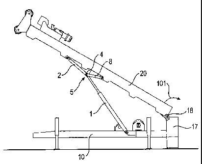
An embodiment of a construction apparatus according to the invention is shown
in
Figs. 1 to 6 in different stages during the erection of the mast. Fig. 1 shows
the
mast in an approximately horizontal transport position, Figs. 5 and 6 show it
in a
vertical operating position.
As shown for example in Fig. 1, the construction apparatus has a base carrier
10,
which is designed as a frame extending in a substantially horizontal direction
and
which can be moved onto a vehicle, not shown here, for transport purposes. The
base carrier 10 has a total of four extendable supports 15, by means of which
the
base carrier 10 rests on the ground 99.
Through a pivot joint 18 having a horizontal pivot axis a mast 20 is linked in
a
pivotable manner to the base carrier 10 between the transport position
illustrated
in Fig. I and the vertical operating position illustrated in Figs. 5 and 6. On
a front
CA 02666892 2009-05-26
-8-
side 61 of the mast 20 a drilling sledge 29 is supported on the mast 20 by
being
displaceable longitudinally of the said mast 20. The drilling sledge 29 can
have
e.g. a rotary drive or a roto-percussive drive for a drill rod not illustrated
in the
Figures. For longitudinal displacement of the drilling sledge 29 along the
mast 20
a rope winch 11 is arranged on the base carrier 10.
To erect the mast 20 from the transport position shown in Fig. 1 into the
operating
position shown in Figs. 5 and 6 two hydraulic cylinders 1 and 2 are provided
that
are arranged in series. The first hydraulic cylinder 1 is linked on its one
side to the
base carrier 10 and on its opposite lying other side it is linked in a
connecting
section 5 to the second hydraulic cylinder 2. The second hydraulic cylinder 2
is in
turn linked to the mast 20 on its side facing away from the first hydraulic
cylinder 1
and the connecting section 5. The linkage of the first hydraulic cylinder 1 to
the
base carrier 10 is effected via the cylinder housing of the first hydraulic
cylinder 1,
whereas the linkage of the second hydraulic cylinder 2 to the mast 20 is
effected
via the piston rod of the second hydraulic cylinder 2, i.e. the connecting
section 5
connects the piston rod of the first hydraulic cylinder 1 to the cylinder
housing of
the second hydraulic cylinder 2.
In order to prevent the connecting section 5 located between the two hydraulic
cylinders 1 and 2 from bending outwards during the erection of the mast 20, a
bar-
shaped coupling rocker-arm 8 is provided which is linked on its one end to the
mast 20 and on its other end to the two hydraulic cylinders 1 and 2 in the
connecting section 5. The two hydraulic cylinders 1 and 2 and the coupling
rocker-
arm 8 are pivotably connected to one another about a common pivot axis 6 in
the
connecting section 5. The pivot axis of the pivot joint 18, the common pivot
axis 6,
the pivot axis of the linkage of the first hydraulic cylinder 1 to the base
carrier 10,
the pivot axis of the linkage of the second hydraulic cylinder 2 to the mast
20 and
the pivot axis of the linkage of the coupling rocker-arm 8 to the mast 20
extend
parallel to one another.
CA 02666892 2009-05-26
-9-
On a mast's rear side 62, which faces away from the mast's front side 61 and
faces towards the first hydraulic cylinder 1 and also towards the base carrier
10 in
the transport position depicted in Fig. 1, two projections 21 and 22 are
provided on
the mast 20. To the first projection 21 the coupling rocker-arm 8 is linked
and to
the second projection 22 the second hydraulic cylinder 2 is linked.
As shown in Fig. 1 in particular, in the transport position of the mast 20 the
second
hydraulic cylinder 2 extends at a very small angle with respect to the
longitudinal
axis 100 of the mast 20. Therefore the forces exerted by the second hydrau(ic
cylinder 2 on the mast 20 act to a large degree parallel to the longitudinal
axis 100
and only to a very small degree in a perpendicular fashion to the longitudinal
axis
100 in the erecting direction 101. In order to ensure in this case, too, an
especially
effective force transmission from the first hydraulic cylinder 1 to the mast
20 in.the
erecting direction 101, a spacer 4 is provided which protrudes from the
connecting
section 5 and rests in the transport position illustrated in Fig. I with a
front-side
supporting surface 41 longitudinally on the mast 20. On its side facing away
from
the mast the spacer 4 is connected in the connecting section 5 by way of the
pivot
axis 6 to the two hydraulic cylinders 1 and 2 and can thus transfer the forces
exerted by the first hydraulic cylinder 1 to the mast 20.
The spacer 4 is arranged at the end of the coupling rocker-arm 8, i.e. upon
rotation of the coupling rocker-arm 8 relative to the mast 20 the spacer 4 co-
rotates with the coupling rocker-arm 8, as illustrated for example in Fig. 4.
As
shown in Fig. 1, in the transport position of the mast 20 the spacer 4 extends
approximately perpendicularly to the longitudinal axis 100 of the mast 20 and
can
therefore transmit forces acting in the erecting direction 101 particularly
well.
In the transport position of the mast 20 the spacer 4 rests with its
supporting
surface 41 on a contact surface 24 that is formed on the mast 20 between the
two
projections 21 and 22 and therefore between the linkage point for the second
hydraulic cylinder 2 and the linkage point for the coupling rocker-arm 8. The
contact surface 24 is provided on the rear side 62 of the mast 20.
CA 02666892 2009-05-26
-10-
In Figs. 1 to 5 the kinematics present during the erection of the mast 20 from
the
transport position into the operating position is shown.
As depicted in Fig. 1, in the transport position of the mast 20 the two
hydraulic
cylinders 1 and 2 are in an at least approximately aligned arrangement and the
connecting section 5 is supported through the spacer 4 on the mast 20.
For erection of the mast 20 the first hydraulic cylinder 1 is operated and
extended
initially. The forces acting in this process are transmitted at least in part
via the
spacer 4 to the mast 20 so that the mast 20 is pivoted upwards in the erecting
direction 101. The second hydraulic cylinder 2 remains retracted so that the
spacer 4 continues to rest on the mast 20. This stage, in which the two
hydraulic
cylinders 1 and 2 leave their aligned arrangement is shown in Fig. 2.
The first hydraulic cylinder 1 is extended further until it has reached its
maximum
operating position. This state is shown in Fig. 3.
Once the first hydraulic cylinder 1 has reached its maximum stroke, the second
hydraulic cylinder 2 is extended for further erection of the mast 20, as
illustrated in
Fig. 4. Through actuation of the second hydraulic cylinder 2 the relative
dimensions of the triangle formed by the second hydraulic cylinder 2, the
coupling
rocker-arm 8 and the mast section between hydraulic cylinder 2 and coupling
rocker-arm 8 change. In particular, the corner-point of the triangle, which is
located remotely from the mast and coincides with the connecting section 5, is
moved away from the mast 20. In doing so, the coupling rocker-arm 8 is pivoted
relative to the mast 20. As a result, the spacer 4, which is connected in a
rotationally fixed manner to the coupling rocker-arm 8 at the end of the
coupling
rocker-arm 8 facing away from the mast, is detached from the contact surface
24
of the mast 20 and is therefore no longer available for a force transmission.
CA 02666892 2009-05-26
-11-
The second hydraulic cylinder 2 is extended further, while the spacer 4
remains
spaced from the mast 20. Finally, the second hydraulic cylinder 2 has also
reached its maximum stroke. In this position, which is shown in Fig. 5, the
mast 20
has reached its vertical operating position. In this operating position the
two
hydraulic cylinders 1 and 2 are located again in an at least approximately
aligned
arrangement.
As illustrated in particular in Figs. 1 and 5, the base carrier 10 has a mast
extension 17, on which the mast 20 rests in the vertical operating position
and
which extends the stroke of the drilling sledge 29. It is on this mast
extension 17
that the pivot joint 18 is arranged.
As shown in Fig. 6, the mast 20 has a two-part telescopic design with a first,
lower
mast section 27 and a second, upper mast section 28, in which case the second
mast section 28 can be telescoped into the first mast section 27. For
displacement
of the two mast sections 27 and 28 relative to each other a hydraulic cylinder
51 is
provided that extends inside the two mast sections 27 and 28. Advantageously,
the mast 20 is designed such that the drilling sledge 29 can be displaced
longitudinally of the two mast sections 27 and 28.