Note : Les descriptions sont présentées dans la langue officielle dans laquelle elles ont été soumises.
CA 02666897 2009-04-17
WO 2008/097286 PCT/US2007/022400
TITLE OF THE INVENTION
METHOD AND SYSTEM FOR DERIVING WIND SPEED IN A STALL
CONTROLLED WIND TURBINE
RELATED APPLICATIONS
This application claims the benefit of U.S. Provisional Patent Application
Serial No. 60/853,036 titled "Method and System for Deriving Wind Speed in a
Stall
Controlled Wind Turbine" filed October 20, 2006. This application is also
related to
U.S. Patent Application No. 11/487,392 titled "Wind Turbine and Method of
Manufacture" filed July 17, 2006, and to U.S. Patent Application No.
11/487,343
titled "Stall Controller and Triggering Condition Control Features for a Wind
Turbine"
filed July 17, 2006. The entirety of each of the above applications is
incorporated by
reference herein.
BACKGROUND OF THE INVENTION
Field of the Invention
Embodiments of the present invention relate to the field of wind turbines, and
in particular to methods and systems for improving the productivity and cost
effectiveness of stall controlled wind turbines by deriving the wind speed in
a cost-
efficient manner and using such information to limit loads in higher winds
where less
annual energy is produced.
Background of the Technology
A problem with existing wind turbines is that, in order to optimize the cost
of
the wind turbine and for reasons related to productivity, loads generally need
to be
1
CA 02666897 2009-04-17
WO 2008/097286 PCT/US2007/022400
minimized. Most large wind turbines address such load problems through use of
an
anemometer, placed, for example, at a location near or on the wind turbine.
The
anemometer allows the speed of the wind to be determined so that wind turbine
operation can be adjusted responsive to wind speed in order to limit loads in
less
productive wind conditions.
However, a difficulty with existing small, stall regulated wind turbines, for
example, is that, as they respond to higher wind conditions and dip into the
stall
region, they lose the ability to determine wind speed. For example, for a
fixed RPM
stall controlled wind turbine, as wind speed increases, the power produced by
the
wind turbine increases up to a maximum level (interchangeably referred to
herein as
"peak power"), without a change in the Revolutions Per Minute (RPM) of the
turbine.
However, as wind speed continues to increase above the speed at which peak
power is produced, the output of the wind turbine actually decreases, due to
aerodynamic characteristics of the turbine. Among other things, this result
means
that after peak power, when the power is decreasing, the decrease may be due
to
the wind speed either rising or falling. There exists no known method or
system in
the prior art to determine wind speed under these conditions, without a
separate
anemometer.
In particular, with a stall regulated wind turbine design, there is an angle
at
which an airfoil is most efficient (i.e., the airfoil has maximum lift over
drag). If the
pitch of the airfoil increases beyond the most efficient angle, lift may
continue to rise,
but drag rises more quickly, such that, at some point, stall is reached. At
stall, lift
does not continue to rise, while drag continues to rise. As a result, the
airfoil
becomes increasingly less efficient as the angle continues to change. From the
2
CA 02666897 2009-04-17
WO 2008/097286 PCT/US2007/022400
point of view of a wind turbine designer, it may be useful to describe this
pitch in
terms of "tip to wind speed ratio" or "TSR."
A further problem, particularly with smaller wind turbines, is that the cost
o.f an
anemometer and features designed to utilize received anemometer information
may
be prohibitive for some intended applications (e.g., low cost residential
use), and the
complexity associated with use of an anemometer may be detrimental to cost,
operation, or reliability, for example. In addition, if an anemometer is
mounted to a
small wind turbine, the information produced from the anemometer under some
conditions may be inaccurate, for example, because the turbine's operation may
interfere with the wind speed reading. The anemometer may also fail, or
produce
inaccurate results under certain conditions.
If the anemometer fails, the wind turbine may be potentially damaged by high
wind conditions. Further, for some small wind turbine applications, if the
anemometer is located separately from the wind turbine, a separate tower or
other
mounting device may be required, which can raise financial, aesthetic, zoning,
or
other concerns.
With regard to the control problem for such wind turbine applications, while
existing methods may be effective for limiting power in fixed RPM wind
turbines,
these existing approaches may not sufficiently limit certain other load
concerns (e.g.,
base bending moments on the tower; main loads on the turbine propeller shaft;
flapwise bending moments on the blade). For example, in some operating
conditions, such loads are independent of power and RPM. In these conditions,
for
example, load may continue to rise with rising wind speed. However, loads in
these
conditions can be controlled if wind speed is known. Thus, costs associated
with the
wind turbine can be reduced (e.g., costs associated with either additional
strength,
3
CA 02666897 2009-04-17
WO 2008/097286 PCT/US2007/022400
rigidity or other features needed to address such increased loads, or with the
need to
use a larger rotor for greater swept area can be reduced).
A typical situation in which increased load conditions exists is as follows.
Wind turbine operation is at peak power, and power and RPM are known. If power
decreases (which it must from peak power for any changing condition), absent
measured information on wind speed, it will be unknown whether the power
decrease is due to increased wind speed or decreased wind speed. As a result,
in
the existing art for a stall controlled wind turbines, for example, the wind
speed
cannot be determined only from RPM and power information.
There is an unmet need in the art, therefore, for cost-efficient and accurate
methods and systems to derive wind speed in stall controlled wind turbines, in
order
to be able to increase the productivity or reduce cost of such wind turbines
(e.g., by
decreasing loads in high winds or by increasing productivity) .
SUMMARY OF THE INVENTION
Embodiments of the present invention overcome the above identified
problems, as well as others, by providing a method and system for accurately
determining wind speed for stall controlled wind turbines, without using an
anemometer or other independent wind speed measuring device. The wind speed
information can be used to improve small wind turbine cost effectiveness. Wind
speed, according to embodiments of the present invention, may be determined by
following or tracking a mapped TSR model with respect to an operating stall
controlled wind turbine in a given TSR range. Further, wind speed may be
determined by decreasing a Ramp Start RPM value upon reaching a maximum
desired power level, and by following a mapped RPM into ramp (the control
going
4
CA 02666897 2009-04-17
WO 2008/097286 PCT/US2007/022400
into RS) for the desired wind speed range. Moreover, wind speed may also be
determined by, upon reaching a desired RPM level, raising the RPM with power.
In
addition, wind speed may also be determined, in accordance with embodiments of
the present invention, by using periodic unloading of the rotor.
One advantage of obtaining wind speed information using the method and
system of embodiments of the present invention is that the wind speed
information
may be provided to a user of the wind turbine (e.g., via a wind speed
readout). More
importantly, embodiments of the present invention allow certain loads on the
wind
turbine to be controlled via use of the wind speed information to control
relevant wind
turbine parameters.
Additional advantages and novel features of the invention will be set forth in
part in the description that follows, and in part will become more apparent to
those
skilled in the art upon examination of the following or upon learning by
practice of the
invention.
BRIEF DESCRIPTION OF THE FIGURES
In the drawings:
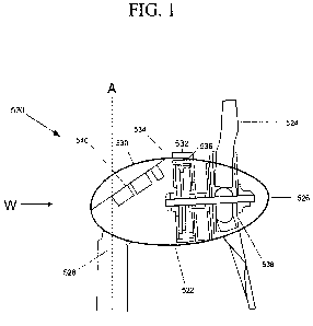
FIG. 1 shows a cross-sectional view of an exemplary wind turbine usable with
embodiments of the present invention;
FIG. 2 is a representative block diagram of various wind turbine components,
including features relating to the method and system for embodiments of the
present
invention;
FIGs. 3A-3B present exemplary flow diagrams of methods of operation in
accordance with embodiments of the present invention;
CA 02666897 2009-04-17
WO 2008/097286 PCT/US2007/022400
FIG. 4 contains a representative system diagram of various components
usable with embodiments of the present invention, as well as the indicated
representative functionality therefor;
FIGs. 5-8 show exemplary graphical mapping of wind speed versus power for
specific TSRs in an exemplary wind turbine, for use in accordance with
exemplary
embodiments of the present invention;
FIG. 9 shows the changes in the "Ramp Start" RPM, power out, and "RPM
into Ramp" parameters with the increase in wind speed, in accordance with an
exemplary embodiment of the present invention;
FIGs. 10A-10C show plots of wind speed vs. RPM, wind speed vs. Electrical
Power, and wind speed vs. TSR, in accordance with an exemplary embodiment of
the present invention; and
FIGs. 11A-11C show plots of wind speed vs. Rotor RPM and Time vs. Rotor
Power, in accordance with an exemplary embodiment of the present invention
DETAILED DESCRIPTION
Description of exemplary embodiments of the present invention will now be
made with reference to the appended drawings.
Referring now to FIG. 2, therein shown is a representative block diagram of
various wind turbine components (a cross-sectional view of an exemplary wind
turbine usable with embodiments of the present invention being shown in FIG.
1),
including features relating to the method and system of the present invention.
As
shown in FIG. 2, the wind turbine 20 includes or is coupled to a processor 22
having
or capable of accessing a repository of data 23, such as a database. The wind
6
CA 02666897 2009-04-17
WO 2008/097286 PCT/US2007/022400
turbine 20 optionally includes a temperature sensor 21 or is coupled to a
temperature sensor 21.
FIG. 3A presents an exemplary flow diagram of one method of operation of an
embodiment of the present invention, in which mapping of tip to wind speed
ratio
(TSR mapping) may be used to determine wind speed. In one embodiment, the
method and system of the present invention includes use of an experimentally
or
otherwise determined mapped range of TSR in which a model wind turbine
operates
as a function of its "Coefficient of Power" or "CP." As shown in FIG. 3A, a
model
mapping TSR for a model stall controlled wind turbine is created or obtained
302.
For example, to create such mapping, an anemometer to measure wind speed may
be used in conjunction with a device for measuring wind tip speed (e.g., based
on
measured blade RPM) to chart tip speed to wind speed ratios of interest for
each
identified TSR. Such ratios of interest may include, for example, ratios
ranging from
that for the wind speed occurring at peak efficiency to the wind speed at
which power
needs to be limited. Generally, these will be TSRs lower than the best
efficiency
TSRs. As an example, the best efficiency (CP) may occur at a TSR of 7 to 1. In
order
to regulate stall, the TSR will have to be reduced to reduce loads. This
regulation
may include situations for all TSRs down to the TSR at which the turbine will
shut
down, or the highest wind speeds that it will operate in (e.g., TSR - 1)
occur. The
mapped model may be obtained or created 302, for example, experimentally or
otherwise (e.g., via modeling).
Referring again to FIG. 3A, the power and RPM of an operating stall
controlled wind turbine, operating at specific TSRs, are measured 304. The
wind
speed of the operating turbine is determined 308 by tracking each identified
TSR 306
in reference to the mapped model. Upon reaching peak power, control is changed
to
7
CA 02666897 2009-04-17
WO 2008/097286 PCT/US2007/022400
fixed power, and the RPM required to maintain that power is monitored 310.
Power
output information and RPM of the turbine are measured, and the wind speed
information is determined 308, by following the mapped model (which may be,
for
example, codified as a series of instructions to be performed by a
microprocessor)
306. By following the mapped results for a given TSR, if the power increases,
the
wind speed must have increased, and with the mapped model, the wind speed can
then be substantially accurately known and followed and then shifted to a new
desired TSR. However, if the TSR is not tracked (interchangeably referred to
herein
as "followed"), the wind speed cannot be determined from the measured power
and
RPM, because there may be different solutions for the same power and RPM
point.
If, however, the TSR is tracked or followed, then the known state can be
maintained,
and thus wind speed can be derived.
The determined wind speed 308 may be corrected 312 based on additional
inputs, such as temperature and operating altitude, if necessary. Upon
reaching a
determined or selected wind speed, the power output of the operating turbine
and/or
the RPM of the operating turbine may be controlled 314.
Referring now to FIG. 3B, therein shown is an exemplary flow diagram of a
second method of operation of an embodiment of the present invention, in which
TSR mapping 320 may also be used to determine wind speed, as described above
in reference to FIG. 3A, with mapping of two additional parameters.
The first additional parameter is a moving "Ramp Start" (RS) and the second
is "RPM into Ramp" (RPM-R). The changes in each of these parameters with the
increase in wind speed are shown in FIG. 9. The RS parameter 902 is a variable
moving "Ramp Start" control RPM. "Ramp Start" is the RPM at which the control
begins to rapidly increase power 904 to control the RPM. For example, if the
RS is
8
CA 02666897 2009-04-17
WO 2008/097286 PCT/US2007/022400
set to a value of 120 watts per RPM, when the RPM reaches a value of about
320,
the control starts increasing power 904 by 120 watts per RPM. This RS value
902 is
reduced if the power rises above a preset maximum desired power level. In the
example shown in FIG. 9, the preset maximum power level is set to about 2400
watts. As shown in FIG. 9, for wind speeds between about 10 m/s and 17 m/s,
the
RS 902 is pushed down by the control to maintain the preset desired 2400 watt
setting.
The second additional parameter "RPM into Ramp" (RPM-R) 906, represents
the RPM of the control going into RS 902. In this example, the RS value
reaches
about 15 RPM at about 13.5 m/s. Therefore, the power required to maintain
control
is adding 15x120 or 1800 watts. This variable is then also mapped for the
desired
wind speed range.
Referring again to FIG. 3B, a RS RPM is selected, and, upon reaching a
desired RPM, the power is increased by the selected RS per RPM. Upon reaching
a
maximum desired power level, the RS parameter is reduced in order to maintain
the
maximum desired power level 324. The control going into RS, RPM into Ramp, is
mapped for the desired range 326. In this embodiment, wind speed can be
selected
or determined by an average value for the variables "RS" and "RPM into Ramp."
Referring now to FIG. 3C, therein shown is an exemplary flow diagram of a
second method of operation of an embodiment of the present invention, in which
wind speed is determined as described above in reference to FIG. 3B, the
difference
being that once a preset RPM is reached, the RPM rises with power as
illustrated in
FIGs. 10A-10C. FIG. 10A shows wind speed vs. RPM with line 1002 representing
manually setting the RPM of the rotor to produce a desired electrical power of
2.17
9
CA 02666897 2009-04-17
WO 2008/097286 PCT/US2007/022400
kW. The wind speed vs. RPM values to produce a desired output of 2.17 kW for
this
example is represented below in Table 1.
wind speed (m/s) rpm Elect. Power (kW) TSR
16 337 2.17 4.10
18 353 2.17 3.82
19 358 2.17 3.67
20 354 2.17 3.45
21 349 2.17 3.24
22 352 2.16 3.12
23 358 2.17 3.03
24 364 2.17 2.95
25 370 2.18 2.88
26 374 2.16 2.80
27 378 2.16 2.73
28 382 2.18 2.66
30 377 2.18 2.45
32 358 2.17 2.18
34 340 2.17 1.95
36 322 2.16 1.74
38 306 2.18 1.57
Table 1- RPM needed to keep Electrical Power = 2.17 kW.
Referring again to FIG. 10A starting with a RS value of about 320 RPM, the
RPM of the RS is allowed to rise up to 380 by RPM.
The fourth exemplary system and method in accordance with an embodiment
of the present invention utilizes a periodic unloading of the rotor, as shown
in FIG.
3D. FIGs. 11A-11C illustrate how the rotor responds to unloading in high vs.
low
winds. This method is used to test the wind speed in areas of operation when
there
is not certainty, for example.
It will be obvious to those of ordinary skill in the art that each of the
above
described methods may be used, alone or in combination with other described
methods, to determine the wind speed of a stall controlled wind turbine.
Upon reaching a desired level of power, because the wind speed (e.g.,
increase or decrease) is known/determined via one of the above described
methods,
a determination may be made with respect to the cost-efficiency of operating
the
CA 02666897 2009-04-17
WO 2008/097286 PCT/US2007/022400
turbine at higher wind speeds. For example, a manufacturer of a turbine may
determine that although it is desirable for a turbine to operate above a given
wind
speed (e.g., 25 m/s), as that wind speed occurs infrequently, increasing the
sturdiness of the turbine for withstanding the high loads at that speed is not
cost-
efficient. Thus, the power output for wind speeds above 25 m/s may be
decreased,
or the turbine may be stopped from operation, until the wind speed has
decreased. If
the turbine is stopped, it may be stopped for a set time (e.g., 2 hours), or
it may be
desirable to continue to operate at reduced load, in order to continue to
monitor wind
speed. If the turbine is stopped for a time, it may be desirable to resume
operation in
a safe, low load mode that allows wind speed to be monitored, until a
determination
may be made as to whether the wind speed is low enough for resuming regular
operation. Alternatively, it may be desirable to simply maintain operation in
high
winds but at reduced loads.
FIGs. 5-8 show exemplary graphical mapping of wind speed versus power for
specific TSRs in an exemplary wind turbine, for use in accordance with
embodiments
of the present invention.
A method and system for operation in very high winds with low loads at a very
low TSR (such as TSR=1) may be used in some embodiments of the present
invention. A very low TSR will exhibit similar loads to a locked rotor.
However, this
low speed operation can be mapped, such as with the method described above in
reference to FIG. 3A, while wind speed can still be reliably measured so that
a
restart wind speed can be selected and the turbine controlled by this
variable.
Air density and the altitude of installation of the wind turbine can also
affect
the determination of wind speed. Thus, to further refine the mapping and to
enable
more accurate determination of when to increase or decrease stall, for
example, air
11
CA 02666897 2009-04-17
WO 2008/097286 PCT/US2007/022400
temperature sensing (e.g., via a temperature sensor incorporated in the wind
turbine
or otherwise coupled to a processor for performing the method of embodiments
of
the present invention) may be included as an input, along with inputting
altitude to
determine air density.
Yet another input that is helpful with further refining the precision of the
method and system of various embodiments of the present invention is
information
on the inertia of the blade of the wind turbine. Blade inertia can, for
example,
typically be modeled in an experimental setting as a function of RPM and/or
other
wind turbine operation characteristics to produce a formula of inertia for
such wind
turbine operating characteristics. Alternatively or in addition to
experimental
methods, modeling by software (e.g., FAST) may be used. Inertia information
can be
further used to refine the determination of wind speed by allowing kinetic
energy due
to change in inertia of the blade to be separated from energy due to changes
in wind
speed, for example. The determination of impact of inertia at any point in
wind
turbine operation can be made, for example, by allowing a small change in RPM
to
occur, and measuring various operational factors in conjunction with use of
the
inertia mapping information.
While more precise results using such additional inputs as air density,
altitude,
and blade inertia are helpful, in some embodiments, such as those in which one
use
of the present invention is to control wind turbine operation in extreme
conditions
(e.g., high winds), the additional precision provided by use of these
additional inputs
may be unnecessary for some conditions.
Once the wind speed is determined to a desired level of accuracy, using, as
necessary, any of the additional inputs described above in addition to the
methods
described above for determining wind speed according to exemplary embodiments
12
CA 02666897 2009-04-17
WO 2008/097286 PCT/US2007/022400
of the present invention, the power of the wind turbine can be controlled to
maximize
efficiency.
The present invention may be implemented using hardware, software or a
combination thereof and may be implemented in one or more computer systems or
other processing systems. In one embodiment, the invention is directed toward
one
or more computer systems capable of carrying out the functionality described
herein.
An example of such a computer system 200 is shown in FIG. 4.
Computer system 200 includes one or more processors, such as processor
204. The processor 204 is connected to a communication infrastructure 206
(e.g., a
communications bus, cross-over bar, or network). Various software embodiments
are described in terms of this exemplary computer system. After reading this
description, it will become apparent to a person skilled in the relevant
art(s) how to
implement the invention using other computer systems and/or architectures.
Computer system 200 can include a display interface 202 that forwards
graphics, text, and other data from the communication infrastructure 206 (or
from a
frame buffer not shown) for display on the display unit 230. Computer system
200
also includes a main memory 208, preferably random access memory (RAM), and
may also include a secondary memory 210. The secondary memory 210 may
include, for example, a hard disk drive 212 and/or a removable storage drive
214,
representing a floppy disk drive, a magnetic tape drive, an optical disk
drive, etc.
The removable storage drive 214 reads from and/or writes to a removable
storage
unit 218 in a well-known manner. Removable storage unit 218, represents a
floppy
disk, magnetic tape, optical disk, etc., which is read by and written to
removable
storage drive 214. As will be appreciated, the removable storage unit 218
includes a
13
CA 02666897 2009-04-17
WO 2008/097286 PCT/US2007/022400
computer usable storage medium having stored therein computer software and/or
data.
In alternative embodiments, secondary memory 210 may include other similar
devices for allowing computer programs or other instructions to be loaded into
computer system 200. Such devices may include, for example, a removable
storage
unit 222 and an interface 220. Examples of such may include a program
cartridge
and cartridge interface (such as that found in video game devices), a
removable
memory chip (such as an erasable programmable read only memory (EPROM), or
programmable read only memory (PROM)) and associated socket, and other
removable storage units 222 and interfaces 220, which allow software and data
to be
transferred from the removable storage unit 222 to computer system 200.
Computer system 200 may also include a communications interface 224.
Communications interface 224 allows software and data to be transferred
between
computer system 200 and external devices. Examples of communications interface
224 may include a modem, a network interface (such as an Ethernet card), a
communications port, a Personal Computer Memory Card International Association
(PCMCIA) slot and card, etc. Software and data transferred via communications
interface 224 are in the form of signals 228, which may be electronic,
electromagnetic, optical or other signals capable of being received by
communications interface 224. These signals 228 are provided to communications
interface 224 via a communications path (e.g., channel) 226. This path 226
carries
signals 228 and may be implemented using wire or cable, fiber optics, a
telephone
line, a cellular link, a radio frequency (RF) link and/or other communications
channels. In this document, the terms "computer program medium" and "computer
usable medium" are used to refer generally to media such as a removable
storage
14
CA 02666897 2009-04-17
WO 2008/097286 PCT/US2007/022400
drive 214, a hard disk installed in hard disk drive 212, and signals 228.
These
computer program products provide software to the computer system 200. The
invention is directed to such computer program products. It will be recognized
by
those of ordinary skill in the art that different variations of the computer
system 200
may be used to successfully implement embodiments of the present invention.
For
example, wired or wireless communication interfaces may be used with equal
success.
Computer programs (also referred to as computer control logic) are stored in
main memory 208 and/or secondary memory 210. "Set points," such as elevation,
and other technician-input or usable adjustable parameters may also be set and
stored in memory. Computer programs (such as updated and improved performance
versions) may also be received via wireless communications interface 224. Such
computer programs, when executed, enable the computer system 200 to perform
the
features of the present invention, as discussed herein. In particular, the
computer
programs, when executed, enable the processor 204 to perform the features of
the
present invention. Accordingly, such computer programs represent controllers
of the
computer system 200.
In an embodiment where the invention is implemented using software, the
software may be stored in a computer program product and loaded into computer
system 200 using removable storage drive 214, hard drive 212, or
communications
interface 224. The control logic (software), when executed by the processor
204,
causes the processor 204 to perform the functions of the invention as
described
herein. In another embodiment, the invention is implemented primarily in
hardware
using, for example, hardware components, such as application specific
integrated
CA 02666897 2009-04-17
WO 2008/097286 PCT/US2007/022400
circuits (ASICs). Implementation of the hardware state machine so as to
perform the
functions described herein will be apparent to persons skilled in the relevant
art(s).
In yet another embodiment, the invention is implemented using a combination
of both hardware and software.
While the present invention has been described in connection with preferred
embodiments, it will be understood by those skilled in the art that variations
and
modifications of the preferred embodiments described above may be made without
departing from the scope of the invention. Other embodiments will be apparent
to
those skilled in the art from a consideration of the specification or from a
practice of
the invention disclosed herein. It is intended that the specification and the
described
examples are considered exemplary only, with the true scope of the invention
indicated by the following claims.
16