Note : Les descriptions sont présentées dans la langue officielle dans laquelle elles ont été soumises.
CA 02669993 2009-05-15
WO 2008/076989 PCT/US2007/087809
AUTOMATED IMAGING OF PART INCONSISTENCIES
BACKGROUND
A wide variety of nondestructive evaluation methods (nondestructive inspection
NDI), such as ultrasonics, eddy current, x-ray, magnetic resonance, and
microwave,
have been utilized to inspect post-manufacture parts, which may comprise metal
and/or
composite and/or ceramic parts or other types of parts. Both water-based,
gantry-style
systems and portable instruments have been utilized to conduct this
evaluation. Some
of the prior art methods conduct scans of the post-manufacture parts, and then
print out
full-scale paper plots of the parts or the inconsistency areas which are then
aligned over
the parts in order to repair the part inconsistencies. Sometimes, the
inconsistency
areas of the printed plot are cut-out in order to trace the inconsistencies on
the parts.
Other methods overlay the printed plot with a transparent Mylar sheet in order
to trace
the outlines of any inconsistencies on the Mylar, which is then laid over the
part in order
to trace the inconsistencies onto the part for repair of the inconsistencies.
One or more
of these methods may be costly, may take substantial time, may be difficult to
administer, may be inefficient, may be inconsistent, may lead to error, may
not allow for
repeatability, and/or may experience other types of problems.
An inspection process is needed which may solve or reduce one or more
problems associated with one or more of the prior art methods.
SUMMARY
In one aspect of the disclosure, a method of displaying an image of an
inconsistency on a part is provided. In one step, the part is scanned (NDI)
for
inconsistencies. In another step, the inconsistency on the part is located. In
still
another step, the image of the inconsistency is displayed on the part.
In another aspect of the disclosure, another method of displaying an image of
an
inconsistency on a part is provided. In one step, locations of reference
points located
on the part are determined. In another step, the part is scanned (NDI) for
inconsistencies utilizing at least one of a non-destructive device. In still
another step,
the inconsistency in and/or on the part is located. In yet another step, the
image of the
inconsistency is displayed on the part.
In a further aspect of the disclosure, a part is provided which had a laser
image
of an inconsistency displayed on the part. The part was non-destructively
scanned
-1-
CA 02669993 2011-11-04
(NDI), and the inconsistency was located. Coordinates of the inconsistency
were
provided to a laser projection device which displayed the laser image on the
part.
In accordance with one aspect of the invention, there is provided a method of
displaying an image of an inconsistency on a part. The method involves
determining
locations of reflective markers located on the part utilizing at least one of
a light
emitting device and a laser emitting device to reflect at least one of a light
beam and a
laser beam off the reflective markers located on the part. The method also
involves
scanning the part utilizing a non-destructive inspection device to determine
the
inconsistency of the part, locating the inconsistency of the part in X, Y, and
Z
coordinates by comparing data from the scanning of the part with the
determined
locations of the reflective markers located on the part, and displaying the
image of the
inconsistency on the part using at least one of a laser projection device to
project the
image of the inconsistency on the part using the located X, Y, and Z
coordinates of the
inconsistency and a printing device to print the image of the inconsistency on
the part
using the located X, Y, and Z coordinates of the inconsistency.
The part may be at least one of an aircraft part and a spacecraft part.
The non-destructive inspection device may include an ultrasonic scanning
device.
The locations of at least six reflective markers located on the part may be
determined.
The reflective markers may include at least one of reflective tape and
reflective
targets.
Determining the locations of the reflective markers located on the part may
involve utilizing a photogrammetry device as the light emitting device.
Determining the locations of the reflective markers located on the part may
involve utilizing a laser tracker as the laser emitting device.
Locating the inconsistency of the part may involve utilizing at least one
computer.
-2-
CA 02669993 2011-11-04
Locating the inconsistency of the part may involve using at least one of
hardware and software to determine a location of the inconsistency based on
the
scanning data showing an irregular shape of the part.
Displaying the image of the inconsistency on the part may involve utilizing
the
laser projection device to project the image of the inconsistency on the part
using the
located X, Y, and Z coordinates of the inconsistency.
Displaying the image of the inconsistency on the part may involve utilizing
the
printing device to print the image of the inconsistency on the part using the
located X,
Y, and Z coordinates of the inconsistency.
The method may further involve reworking the part utilizing the displayed
image.
The method may be automated.
In accordance with another aspect of the invention, there is provided a
computer-readable memory encoded with codes for directing a microprocessor to
implement the method.
These and other features, aspects and advantages of the disclosure will
become better understood with reference to the following drawings, description
and
claims.
BRIEF DESCRIPTION OF THE DRAWINGS
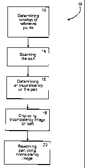
Figure 1 illustrates a flow-chart of one embodiment of the disclosure of a
method of displaying an image of an inconsistency on a part.
Figure 2 illustrates a perspective view of one embodiment of the disclosure of
an inconsistency being located on a part and an image of the inconsistency
being
displayed on the part.
DETAILED DESCRIPTION
The following detailed description is of the best currently contemplated modes
of carrying out embodiments of the disclosure. The description is not to be
taken in a
limiting sense, but is made merely for the purpose of illustrating the general
principles
-3-
CA 02669993 2011-11-04
of embodiments of the disclosure, since the scope of the embodiments is best
defined
by the appended claims.
In one embodiment of a method, as depicted in Figure 1, a method 10 of
displaying an image of an inconsistency on a part, component, or structure is
provided. The method may be automated, and/or may utilize for example, without
limitation, software and/or hardware such as one or more computers. The part
may
comprise a vehicle part such as, but not limited to, an aircraft, auto, bus,
train, ship or
satellite part. In other embodiments, the part may comprise any type of part,
including
non-aeronautical related parts, which are made of metal and/ composites and/or
ceramic or other materials. "Inconsistencies," as the term is used in the
appropriate
context throughout this disclosure, refers to the difference between one or
more
measured characteristics of a composite structure under test (and potentially
effected
by exposure to factor(s) including, but not limited to, thermal load(s),
moisture,
galvanic action, structural load(s), lightning, or electrical arcing) with
expected values
for the same characteristics of an analogous composite structure unaffected by
exposure to those factors.
As shown in Figures 1 and 2, in step 12, a determination may be made as to
locations of reference points 13 located on the part 15. In one embodiment, up
to six
reference points 13 may be located on the part. Figure illustrates 6 reference
points
13. The reference points 13 may comprise reflective markers, such as without
limitation reflective tape, and or reflective targets which are dispersed over
various
locations of the part. These locations may or may not be pre-determined. In
other
embodiments, any number, type, configuration, size, and/or location of
reference
points 13 may be utilized. The determination as to the locations of the
reference
points 13 on the part 15 may be made utilizing a light emitting device 17,
such as
without limitation a photogrammetry device, and/or a laser emitting device 19,
such as
without limitation a laser tracker, which may reflect light and/or laser beams
off the
reference points 13. The locations, configurations, and/or magnitudes of the
reflected
light and/or laser beams may then be determined in order to determine the
locations of
the reference points on the part. In other embodiments, the determination as
to the
-4-
CA 02669993 2011-11-04
locations of the reference points 13 on the part 15 may be made utilizing any
type of
device known in the art including without limitation a printer.
In step 14, the part 15 may be scanned (non-destructively inspected NDI) for
inconsistencies. The part 15 may be scanned utilizing any type of non-
destructive
scanning device 21 known in the art, such as, but not limited to the use of an
ultrasonic scanning device, an infrared scanning device, a magnetic resonance
scanning device, or X-ray scanning device. The scan of the part may include
taking
ultrasonic images of the entire part, including the locations of the part
where the
reference points may be located. In such manner, images, data, and/or
information
regarding the part's shape and/or depth may be obtained. In other embodiments,
the
scan of the part may comprise only certain areas of the part, and/or other
information
regarding the part.
In step 16, an inconsistency 23 on the part 15 may be determined. This step
may comprise determining one or more coordinate X,Y, and Z locations of one or
more inconsistencies 23 on the part 15. The location of any inconsistencies
may be
determined by comparing the data and/or information obtained from the scan of
the
part to the locations of the known location reference points. This may be
accomplished, without limitation, utilizing one or more computers and/or
software. In
such manner, the exact location and/or configuration of the inconsistency on
the part
may be determined.
In step 18, an image 25 of the inconsistency 23 may be displayed on the part
15. This step may be accomplished utilizing a laser projection device 27 by
transforming the location coordinate data of the inconsistency into data that
the laser
projection device can read. In other embodiments, any type of device known in
the art
may be utilized in order to display the inconsistency image on the part, such
as
without limitation, plotting, and/or printing the image 25 onto part 15.
The laser projection device 27 may display the image 25 on the part 15 by
locating the known location reference points 13 on the part 15, and
subsequently
displaying the image 25 relative to known location reference points 13. In
such
manner, the image 27 may be displayed in the substantially correct location on
the
-5-
CA 02669993 2011-11-04
part 15. In other embodiments, the image 25 may be displayed or printed on the
part
15 utilizing various methods to locate the image 25 on the part such as, but
not limited
to a plotter and/or a printer.
In step 20, the nature of the inconsistency may be better appreciated
utilizing
the image 25 of the inconsistency displayed on the part 15. The image 25
projection
on the part may allow a person to see and appreciate and/or a machine to
quantify the
location where the part has inconsistencies. This may help with any
inconsistency
trimming needed, rework bond locating and sizing, and/or new or additional ply
sizing,
to name only a few examples. This may allow analysis and work on the part to
be
performed in less time, with more consistency, with less error, in a less
difficult
manner, and/or with less human interaction, and/or one or more other problems
experienced with one or more of the prior art methods may be reduced.
In yet another embodiment, a part is provided which had a laser image of an
inconsistency displayed on one or more surfaces of the part. The part may have
been
non-destructively scanned, such as ultrasonically scanned, and the
inconsistency
location may have been determined based on the non-destructive inspection. The
coordinates of the inconsistency location may have been provided to a laser
projection
device which displayed the laser image of the inconsistency on the part. The
part may
be fabricated from metal and/or composite and/or ceramic material for an
aircraft, a
spacecraft, and/or other type of part such as a non-aeronautical part. The
part may
have been reworked based on the displayed inconsistency laser image.
It should be understood, of course, that the foregoing relates to exemplary
embodiments of the disclosure and should not be construed as limiting of the
invention
as construed in accordance with the following claims.
-6-