Note : Les descriptions sont présentées dans la langue officielle dans laquelle elles ont été soumises.
WO 2008/064467 PCT/CA2007/002128
.. CA 02671111 2009-06-01
1 IDENTITY THEFT PROTECTION AND NOTIFICATION SYSTEM
2
3 FIELD OF THE INVENTION
4 [0001] The present invention relates to a secure monitoring system and
methods for the
notification of identity usage.
6 BACKGROUND OF TI-iE INVENTION
7 [0002] Personal information and identification are generally regarded as
important and
8 worthy of at least a minimum attempt for security. People need
identification for driving,
9 obtaining medical care and applying for jobs. Identification is also
required by credit card
companies and banks to authorize the use of their services and also by
government officials
11 for bor&r security and airline travel security.
12 100031 Credit agencies monitor the activity of people through their
identification and the
13 use of various services such as a credit card for day-to-day purchases.
This activity is
14 evaluated and people are given a credit rating which is essentially a
"report card" for their
ability to pay back loans and other credit purchases they may require.
Therefore the use of
16 sensitive identification information greatly affects a person's ability to
mortgage property or
17 establish credit for making large purchases.
18 100041 If a person's identification has been misplaced or stolen, it could
be used by an
19 unauthorized person in various fraudulent ways. This activity could lead to
negative results
applied against the person's credit rating and/or other undesired outcomes.
The advent of
21 electronic commerce (E-commerce) has presented further challenges in
protecting identity
22 information since identification numbers (i.e. phone numbers, social
security numbers, credit
23 card numbers etc.) may be sent over public networks and information may be
stored in an
24 electronic database which is connected to such a public network.
[0005J The Internet enabled World Wide Web provides wide access to information
26 flowing across its supporting infrastructure allowing a person's identity
to be essentially
27 "stolen" since any unauthorized use of their personal information can be
accomplished
28 quickly and in many different locations which may or may not be
significantly remote to the
29 person's place of residence. By the time the person i-ealizes that
unauthorized activity has
-1-
WO 2008/064467 PCT/CA2007/002128
CA 02671111 2009-06-01
I occurred, the damage has often already been done and it is up to the person
to rectify any
2 incorrect or fraudulent activity.
3 [00061 Credit report services such as Equifax attempt to deal with
identification theft by
4 providing an automated credit watch service, Equifax Credit WatchT"'. This
service monitors
subscribing users' credit reports and provides alerts to the customers when
activity occurs
6 relating to their credit reports. The alerts are presented to the customer
either within 24 hours
7 or 7 days depending on the level of service paid for. A delay of even 24
hours is sufficient to
8 allow a person's identification to be used in many ways and many times.
Therefore, although
9 monitoring is done, it is not nearly as responsive as necessaly to track E-
commerce activities.
Furthermore, credit report monitoring mainly relates to financial information
and does not
11 encompass unauthorized use of other forms of identification such as a
passport or driver's
12 license.
13 [0007] There exist various systems which monitor transaction activity and
credit report
14 activity, namely those taught in U.S. 2003/0195859 Al to Lawrence, U.S.
2002/0133462 Al
to Shteyn, U.S. Patent No. 6,064,990 to Goldsmith, U.S. 2002/0169747 to
Chapman et al.,
16 and U.S. 2002/0087460 Al to Homung. These documents teach various methods
of tracking
17 a user's credit rating and/or transaction activities and notifying them of
these changes. To
18 identify and notify the user, these systems require the storage of
sensitive information. The
19 systems are typically connected to public networks such as the World Wide
Web and,
therefore, this sensitive information is also prone to security risks and
theft. The information
21 stored is available to unauthorized personnel through fraudulent activities
and thus the
22 information is not secure.
23 100081 To protect the transfer and storage of sensitive information, it is
well known to
24 encrypt and decrypt the information at the endpoints of the transmission.
U.S. Patent No-
6,012,144 to Pickett teaches "slicing" and encrypting data before transmission
wherein each
26 "slice" is decrypted and re-assembled at the receiving end. However,
although the
27 transmission of the sensitive data is secure, the issue remains as to the
storage of the intact
28 information. U.S. patent application publication, No. U.S. 2003/0070101 Al
to Buscemi
29 provides a method for encrypting information and distributing a public key
to decrypt. The
key is distributed first to the owner of the information and can be
redistributed as they desire.
-2-
WO 2008/064467 CA 02671111 2009-06-01 PCT/CA2007/002128
I Again this method requires the storage of the intact confidential
information which is prone
2 to theft and/or unauthorized access.
3 [0009] It is therefore an object of the present invention to obviate or
mitigate at least
4 some of the above mentioned disadvantages. More specifically, a system and
method is
therefore required that can provide secure monitoring and protect sensitive
information both
6 in storage and during communication.
7 SUMMARY OF THE INVENTION
8 [0010] In one aspect, a method for updating information associated with
identification
9 information is provided. The method comprises receiving a secure version of
an
identification datum and an indication of an incident associated with the
identification datum,
11 the incident being related to the identification datum; comparing the
secure version of the
12 identification datum to stored identification data; and if the stored
identification data
13 comprises the identification datum, updating information specific to the
datum.
14 [00111 In another aspect, a method of identity monitoring is provided
comprising a
notification system storing biometric identification information and contact
information for
16 each of at least one subscriber, the identification being stored in a
secure manner; the
17 notification system receiving a query from a verifier indicative of the use
of queried
18 biometric identification informa.tion; the notification system using the
query to retrieve
19 contact information corresponding to the queried biometric identification
information if the
queried biometric identification information corresponds to one of the at
least one subscriber;
21 and if retrieved, the notification system using the contact information to
notify the one of the
22 at least one subscriber of the use of the queried biometric identification
infoi-mation.
23 [0012] In yet another aspect, a notification system for identity monitoring
is provided
24 comprising a storage device for storing biometric identification
information and contact
information for each of at least one subscriber, the biometric identification
information being
26 stored in a secure manner; an interface adapted to enable a verifier to
submit a query
27 indicative of the use of queried biometric identification information; and
a server connected
28 to the interface and the storage device, the server capable of receiving
the query from the
29 interface and transmitting a notification message to each of the at least
one subscriber over a
communication channel, the server using the query to retrieve contact
information
-3-
WO 2008/064467 PCT/CA2007/002128
CA 02671111 2009-06-01
1 corresponding to the queried biometric identification information if the
queried biometric
2 identification information corresponds to one of the at least one
subscriber; and if retrieved,
3 the server using the contact information to notify the one of the one of the
at least one
4 subscriber of the use of the queried biometric identification information.
[0013] In yet another aspect, there is provided a notification system for
identity
6 monitoring comprising: an alert system comprising a database storing
encrypted versions of
7 identification data for one or more subscribers; and at least one
verification agent comprising
8 contact information for the one or more subscribers; wherein the alert
system is configured to
9 receive queries from one or more verifiers, the queries comprising encrypted
versions of
identification data to be verified; compare the received encrypted versions to
those stored in
11 the database; and send a result of the comparison to one of the at least
one verification agent
12 for notifying a respective one of the subscribers.
13 [0014] In yet another aspect, there is provided a method for anonymously
storing
14 identification data comprising: separating the identification data into a
plurality of fields
comprising a first field containing an identification number and a second
field containing
16 information associated with the identification number; applying a one-way
hash function to
17 each the first field and the second field to generate a first hashed field
and a second hashed
18 field respectively; and storing the first hashed field with the second
hashed field; wherein the
19 first and second hashed fields are each compared to corresponding input
hashes for verifying
the identification data.
21 [0015] In yet another aspect, there is provided a memory for storing
identification data
22 for access by an identity verification application program being executed
on a data processing
23 system comprising one or more data structures stored in the memory, the
data structures
24 including a plurality of hashed data fields stored with each other in the
memory, the plurality
of hashed data fields comprising a first hashed field of a first field of the
identification
26 information containing an identification number, and a second hashed field
of a second field
27 of the identification information containing information associated with
the identification
28 number.
-4-
WO 2008/064467 PCT/CA2007/002128
CA 02671111 2009-06-01
I BRIEF DESCRIPTION OF THE DRAWINGS
2 [0016] Embodiments of the invention will now be described by way of example
only
3 with reference to the appended drawings wherein:
4 [0017) Figure 1 is a block-type diagram of an identity monitoring system.
[0018] Figure 2 is a schematic diagram of an implementation of the system of
Fig 1
6 providing notification via Email and wirelessly through a cellular phone.
7 [0019] Figure 3 is a block-type diagram of an encryption function.
8 [00201 Figure 4 is a schematic representation of a database.
9 [0021] Figure 5 is a schematic representation of a login page provided by a
web-browser.
100221 Figure 6 is a schematic representation of an information entry
interface for
11 supplying the input of Figure 3.
12 [0023] Figure 7 is a flow chart showing the general steps in an identity
monitoring
13 procedure.
14 [0024] Figure 8 is a flow chart showing the subscriber registration
procedure of Fig 7.
[0025) Figure 9 is a flow chart showing the verifier registration procedure of
Fig 7.
16 100261 Figure 10 is a flow chart showing the notification procedure of Fig
7.
17 [0027] Figure 11 is a flow chart showing the encryption procedure of Fig
10.
18 [0028] Figure 12 is a flow chart showing the subscriber response procedure
of Fig 7.
19 100291 Figure 13 is a flow chart showing the unmatched category filing
procedure of Fig
12.
21 [0030] Figure 14 is a block-type diagram illustrating a second embodiment
of the present
22 invention involving the transmission of information between multiple
subscribers.
23 100311 Figure 15 is a flow chart showing a secure bulk message posting
procedure.
-5-
WO 2008/064467 CA 02671111 2009-06-01 pCT/CA2007/002128
1 [0032] Figure 16 is a flow chart showing a bulk message inquiry procedure
for non-
2 subscribers.
3 [00331 Figure 17 is a flow chart showing a bulk message inquired procedure
for
4 subscribers.
100341 Figure 18 is a flow chart showing an email filtering procedure.
6 100351 Figure 19 is a schematic representation of a pair of security levels.
7 100361 Figure 20 is a flow chart showing a process for linking other
identification
8 numbers to the core identification numbers of Figure 19.
9 100371 Figure 21 is a flow chart showing a solicitation procedure using the
unmatched
identification numbers of Figure 20.
11 [00381 Figure 22 is a schematic representation of an embodiment of the
identity
12 monitoring system utilising notarized registration.
13 100391 Figure 23 is a flow chart showing a notarized registration
procedure.
14 [0040] Figure 24 is a flow chart showing the steps in an embodiment of the
identity
monitoring system utilising random charge registration.
16 [0041) Figure 25 is a schematic representation of an embodiment of the
identity
17 monitoring system coniprising a verification mailbox.
18 [0042] Figure 26 is a flow chart showing a procedure for handling
verification attempts
19 using the mailbox of Figure 25.
100431 Figure 27 is a block-type diagram illustrating an embodiment of the
identity
21 monitoring system for communicating information between an ID holder and an
ID issuer.
22 [0044) Figure 28 is a schematic representation of a web-based application
program
23 interface (API) for communicating between an ID holder and an ID issuer.
24 [0045] Figure 29 is a flow chart showing a procedure for reporting to an ID
issuer, an
incident associated with identification information for an ID holder.
-6-
WO 2008/064467 PCT/CA2007/002128
CA 02671111 2009-06-01
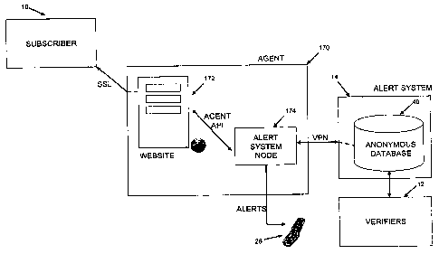
1 [00461 Figure 30 is a schematic block diagram of an identity monitoring
system utilizing
2 an alert system agent.
3 [0047] Figure 31 is a schematic block diagram showing further detail of the
alert system
4 node in Figure 30.
[00481 Figure 32 is a schematic block diagram illustrating a central anonymous
6 identification information database connected to a plurality of verifiers
and a plurality of alert
7 system agents.
8 [0049J Figure 33 is a flow diagram illustrating a notification process for
the system
9 shown in Figure 30.
[0050J Figure 34 is a flow diagram illustrating the notification process of
Figure 33
11 including a verifier-to-ID issuer communication channel.
12 DETAILED DESCRIPTION OF THE INVENTION
13 [0051] Referring therefore to Figure 1, a secure con-imunication system for
identity
14 monitoring 10 ("the system") is generally comprised of a number of
correspondents, for
example, a verifier 12, a notification or alert system 14 and a subscriber 16.
A verifier or
16 verification entity 12 is any entity that needs to verify the identity of
the subscriber 16 that
17 they are dealing with. These entities may include but shall not be limited
to credit card
18 merchants, credit card issuers, banks, loan companies, employers, insurance
companies,
19 health care providers, landlords, leasing companies, rental companies or
govemment agencies
such as immigration, customs, law enforcement, social security and department
of motor
21 vehicles.
22 100521 A subscriber 16 is a person or organization who is the authorized
holder of
23 personal or sensitive information and wishes to be notified of any use of
that personal or
24 sensitive information. The personal or sensitive information may belong to
the subscriber 16
or a dependant of the subscriber 16 such as a child or a deceased relative.
Subscribers 16
26 may include but shall not be limited to an individual (i.e. a
consumer/citizen), or a business
27 organization that uses various identification/registration numbers and
credit cards.
-7-
WO 2008/064467 CA 02671111 2009-06-01 PCT/CA2007/002128
1 [00531 Subscriber 16 may also comprise any entity having the right or
permission to act
2 on another's behalf, such as an executor or power of attorney. Such
subscribers may for
3 example hold power of attorney or otherwise be acting on behalf of, for
example, the estate of
4 a deceased person or for someone who is otherwise incapacitated, e.g.
someone who is
infirmed. Similarly, a parent or guardian of a child may also be considered
someone acting
6 on another's behalf. Therefore, although the child may be a minor, a
responsible adult may
7 subscribe to the system 10 on their behalf. A subscriber 16 may be
registered or unregistered.
8 A registered subscriber 16 is a subscriber 16 that has registered with, and
been verified by the
9 alert system 14.
100541 An alert system 14 facilitates the monitoring process and possesses the
ability to
11 securely correlate identification data with the contact information of a
subscriber 16.
12 [0055J By way of illustration, an electronic implementation of the network
used to
13 implement the system 10 via the Internet and World Wide Web is shown in
Figure 2. Every
14 entity involved in the system 10 is connected to the World Wide Web through
existing
Internet infrastructure (Internet) 20. This may be provided through an
available
16 communication means such as a digital subscriber line (DSL) or an
equivalent internet
17 service provider (ISP) such as dial-up or cable providers. The verifier 12
has a computer 22
18 connected to the Internet 20 and in the particular embodiment illustrated
in Figure 2, is
19 verifying a loan application by checking the authenticity of a driver's
license 24. It will be
appreciated that the system 10 may be implemented over any communication
channel or
21 network using any infrastructure supporting such a communication channel or
network and
22 the invention should not be limited to the Internet and World Wide Web as
illustrated in
23 Figure 2. For example the system 10 may be implemented over a local area
network (LAN),
24 intranet, wide area network (WAN) etc. Any reference herein to a specific
network or
infrastructure is purely for illustrative purposes and is not intended to
limit the invention.
26 100561 The alert system 14 has a computer (server) 26 with a suitable
processor (not
27 shown). The server 26 is connected to a communication network such as the
Internet 20 and
28 coordinates the notification and alert procedures of the alert system 14.
The server 26
29 includes an interface to enable a human to interact with the alert system
14. For example, the
interface may comprise a website or other means for communicating with the
alert system 14.
31 The subscriber 16 is preferably notified by receiving both an Email message
accessible via a
-8-
WO 2008/064467 PCT/CA2007/002128
CA 02671111 2009-06-01
I personal computer 25 and by receiving a second message such as a text
message via a
2 wireless device 28. However it will be appreciated the subscriber 16 may
also receive a
3 notification message via an Email message only, a text message only or may
receive any
4 number of notification messages via any number of acceptable devices.
According to the
example shown in Figure 2, a wireless service provider 27 is connected to the
Internet 20 and
6 communicates to the wireless device 28 by wireless transmission and to the
personal
7 computer 25 via the Internet 20 or similar computer network.
8 100571 The server 26 may include an encryption module 30 to enable the
encryption of
9 data for secure storage. Figure 3 shows a functional representation of an
encryption module
30. The encryption module 30 applies an encryption function 34 to rin input 32
to generate an
11 encrypted output 36. The input 32 generally comprises data which is to be
securely stored on
12 the server 26. Once the input 32 is converted into an enciypted output 36,
the input 32 is
13 preferably deleted and cannot be retrieved. Thus, even if the database 40
is accessed by an
14 unauthorized party, only encrypted information as opposed to authentic
identification data
can be accessed. It will be appreciated that the encryption module 30 may
reside on the
16 server 26 or may be implemented separately as desired.
17 100581 Data stored by the alert system 14 is preferably stored in a storage
device, such as
18 a database 40, shown in Figure 4. Preferably, an encrypted output 36 is
stored with an
19 indicator 42 and associated contact information 38. This group of
information will
hereinafter be referred to as an entry 44. The contact information stored in
the database 40
21 can be used by the alert system 14 for notifying subscribers 16 by way of a
query related to
22 the use of their identification data. A person skilled in the art would
understand that many
23 entries 44 can be stored in the database 40. The indicator 42 can be
classified as an "M"
24 which means that the entry 44 is matched or a "U" which means the entry 44
is unmatched.
If classified as matched, the entry 44 has been entered into the database 40
by the alert system
26 14 and corresponds to a registered subscriber 16, wherein the alert system
14 can contact that
27 subscriber 16 if that the securely stored information is part of a query
made by a verifier 12.
28 If classified as unmatched, the entry 44 is normally incomplete, and has
been entered into the
29 database 40 by the alert system 14 upon receipt of a query fi=om a verifier
12 that does not
relate to a registered subscriber 16. In this case, the unmatched entry 44 may
be retained for
31 other purposes as discussed below.
-9-
WO 2008/064467 CA 02671111 2009-06-01 PCT/CA2007/002128
1 [0059] A verifier 12 can query and interact with the alert system 14 through
various
2 interfaces. A login interface 50 is shown in Figure 5 and a verification
interface 60 is shown
3 in Figure 6. The interfaces 50, 60 may be accessed by the verifier 12 via an
application
4 program interface (API) which is loaded on their computer 22 once they have
registered with
the alert system 14 or via a website hosted by the server 26. The login
interface 50 includes a
6 username entry box 52 and a password entry box 54. The login interface 50 is
used to
7 provide access to the verification interface 60 and preferably provides
secure access such as
8 through a secure sockets layer (SSL) connection. The verification interface
60 is also
9 preferably implemented using a secure connection to the alert system 14 such
as through an
SSL connection.
11 10060] The verification interface 60 may be provided by the API or via the
website
12 hosted by the server 26. The verification interface 60 has an
identification number entry box
13 62, a message entry box 64, a status box 66 and is supported by the
encryption module 30. It
14 will be appreciated that the interfaces 50, 60 depicted in the figures are
intended only for
illustration purposes and that any interface that provides a similar
functionality can be
16 provided by the API or the website hosted by the server 26. It will also be
appreciated that
17 the interfaces 50, 60 may be implemented in various languages to facilitate
verification and
18 notification between subscribers and verifiers of different languages. For
example, interfaces
19 50,60 may include language translation functionality for allowing a
verification in one
language to appear as a notification in another language.
21 100611 The general steps involved in the notification and alert procedure
700 are
22 illustrated in Figure 7. The database 40 is built by collecting entries 44.
These entries 44 are
23 collected during the subscriber registration procedure 702. The database 40
is accessed by a
24 verifier 12 once they have completed the verifier registi-ation procedure
704. The registration
procedures occur using a verification entity 705 external to the system 10.
The verification
26 entity 705 receives a request for verification along with the entity's
information and verifies
27 the identity of an entity trying to register with the alert system 14 and
indicates to the alert
28 system 14 whether or not the entity trying to register has supplied valid
information. With a
29 populated database 40, the notification procedure 706 can be executed which
encourages and
facilitates the subscriber response procedure 708.
- l0-
WO 2008/064467 CA 02671111 2009-06-01 PCT/CA2007/002128
1 100621 The subscriber registration procedure 702 is illustrated in Figure 8.
To register
2 with the alert system 14, the subscriber 16 may begin by communicating with
the alert system
3 14, preferably by accessing a website hosted by the server 800. The website
is preferably
4 accessed securely using a secure connection such as an SSL connection to
ensure the
information provided during the registration procedure 702 is kept secure. It
will be
6 appreciated that the website may be accessed by some other party on behalf
of the subscriber
7 16 if permission is so granted. Upon communication with the alert system,
the subscriber 16
8 is presented with a set of options if applicable, or can directly register
with the alert system
9 14.
100631 In this example, upon accessing the website 800 the subscriber 16 has
three
11 options which are: to begin the registration procedure 802, "stake your
claim" 804 or to do
12 an identification search 806. The "stake your claim" option 804 is a
service which may be
13 provided by the alert system 14 to unregistered users to ensure that other
parties cannot
14 register with the alert system 14 using their identification data. The
identification search
option 806 is a service which may be provided by the alert system14 to allow
unregistered
16 users the opportunity to submit a query to determine whether or not an
identification number
17 corresponding to their personal information has been filed as unmatched in
the database and
18 therefore an attempt has been made by a verifier 12 to verify that
particular identification
19 number.
100641 To "stake your claim", the unregistered user may submit a
identification number
21 corresponding to a piece of personal information (i.e. a credit card number
etc.) as well as
22 contact information to the website 808 which uses the encryption module 30
to generate an
23 output 36 for submission to the database 40. The identification number is
stored for future
24 reference such that if another party attempts to register that number, both
parties are notified
of the dispute which should be dealt with before either party can register
with the alert
26 systeml4. The unregistered user is then asked whether they want to
subscribe to the service
27 812. If they choose "No" then the system 10 thanks them for the inquiry 813
and asks them
28 to consider registering in the future. If they choose "Yes" then the
registration option 802 is
29 automatically executed.
[0065] If an unregistered user chooses to perform an identification search
806, they input
31 the identification number of interest 814 and the system enciypts the
number and searches the
-11-
WO 2008/064467 CA 02671111 2009-06-01 PCT/CA2007/002128
1 database 40 for any unmatched entries that contain the encrypted number 815.
This allows an
2 unregistered user to identify whether any verifier 12 has attempted to
validate a transaction
3 using their identification. Any matches are displayed 816 to the
unregistered user and they
4 are asked whether they would like to register 812 based on the activity
which has occurred
using their identification. If they choose "No", then the system 10 thanks
them for the
6 inquiry 813 and asks them to consider registering in the future. If they
choose "Yes" then the
7 registration option 802 is automatically executed.
8 100661 Depending upon the choices presented by the alert system 14, the
registration
9 option 802 is either presented automatically or is initially chosen by the
potential subscriber
16 of the alert system 14. The subscriber 16 provides a set of information
required by the
11 alert system 818 to allow the alert system 14 to determine the authenticity
of the identity of
12 the potential subscriber 16. In this example, the alert system 14 would
generate and send a
13 registered letter to the subscriber 16 to authenticate with a verification
entity 705. The
14 information preferably includes a name, address, phone number and payment
method. The
subscriber 16 can also provide a desired usemame and password 820 if required.
16 [0067] Using the information submitted, the alert system 14 preferably
generates a unique
17 reference number and issue a letter addressed to the subscriber 16. The
letter is preferably
18 sent by registered mail. The subscriber 16 will typically be requested to
present photo
19 identification to pick up the registered letter, and thereby have access to
the reference
number. The subscriber 16 then submits this reference number to the alert
system 16 to
21 authenticate the registration of the subscriber 16.
22 [0068] In this example, the subscriber 16 takes the registered letter to
the verification
23 entity 705 with the reference number, proof of identity and the
identification being verified.
24 The verification entity 705 can be any trusted third party verifying agent
such as the local
police or other government agency. The manual verification allows a trusted
third party to
26 validate the verification. The verification entity 705 communicates with
the alert system 14
27 to indicate whether or not the verification was successful 822. If
verification is successful,
28 the verification entity 705 sends the identification number to the alert
system 14 for input into
29 the system. If the verification is unsuccessful, the verification entity
sends an etror
notification to the alert system 14. Although the subscriber verification
procedure described
31 herein is done manually with a registered letter sent to the subscriber 16
who would typically
-12-
WO 2008/064467 CA 02671111 2009-06-01 PCT/CA2007/002128
I take that registered letter to the verification entity 705, it will be
appreciated that the
2 verification procedure may alternatively be done electronically. For
example, electronic
3 verification can be implemented using a trusted and secure verification
entity 705 which is
4 communicated with via a telephone, the Internet or other communication
media. It will
further be appreciated that verification may be accomplished without the use
of a verification
6 entity 705 wherein the reference number obtained upon receipt of the
registered letter can be
7 communicated to the alert system 14 by the subscriber 16 thereby verifying
the registration.
8 [00691 If the verification entity 705 rejects the registration, the alert
system 14 provides a
9 message indicating that the subscriber 16 cannot be registered 824. If the
verification entity
705 authorizes the registration, the subscriber 16 is asked to input the
identification
11 number(s) they want to protect 826 and the alert system 14 stores this
information with the
12 contact information in the database 40. Preferably, the alert system 14
deletes the
13 information provided during step 818 so that no sensitive information is
stored. In this
14 example, the subscriber 16 would input the number of their issued driver's
license 24. The
subscriber 16 may also wish to protect multiple identification numbers or to
create sub-
16 accounts involving dependants such as minors or for deceased relatives. The
alert system 14
17 would typically allow the subscriber 16 to protect any number of
identification numbers as
18 well as monitoring the identities of dependants or the deceased by offering
sub-accounts as an
19 enhanced service to their account. The subscriber 16 is then asked to input
a desired contact
information 828. The contact information can be a phone number, email address
or any other
21 contact information but for maximum anonymity it is most desirable to
provide an
22 anonymous email address which cannot be linked to any name or address. In
this example,
23 the driver's license number is encrypted and stored with the contact
information in the
24 database 40.
[0070] When encryption of the data is used by the alert system 14, the
encryption
26 procedure 1100 shown in Figure 11 may be used. Following submission of the
identification
27 number 826, the encryption module 30 captures the string to be encrypted
1102. To encrypt
28 the string, the encryption module 30 in the present example applies a 512-
bit hash function
29 1104. This hash function takes the string which is of an arbitrary finite
length and maps it to
a string of a fixed 512-bit length 1] 06. The encrypted value 36 is a compact
representation of
31 the input string 32 and can be used as if it were uniquely identifiable
with that string.
-13-
WO 2008/064467 PCT/CA2007/002128
CA 02671111 2009-06-01
I Therefore the encrypted output 36 is unique to the input 32 but does not
contain the actual
2 identification number, in this case the actual driver's license number.
However a portion of
3 the identification number such as the last 4 digits may be retained to
indicate to the customer
4 which identification number has been used. After encryption, the input
string 32 is deleted
and the output 36 which is an encrypted string is saved in the database 40.
6 100711 Preferably, the encryption module 30 generates a multiple field hash
of the
7 particular identification number. For example, a three field hash may be
used, the three fields
8 corresponding to the issuer of the identification, the type of
identification, and the
9 identification number itself In the example described herein, a three field
hash would
include the government body as issuer, driver's license as type, and the
particular number
11 unique to the card 24 respectively. A multiple field hash may be used to
better distinguish
12 between different identification pieces that have similar numbers. For
example, by including
13 a hash of both the issuer and type, two driver's licenses in different
states and provinces
14 having the same number are still unique. Any number of hash fields can be
used depending
on the particular use of the system 10.
16 [0072] Referring again to Figure 8, once the enciypted identification
number and contact
17 information has been input into the database 40, the setup is completed 830
and the
18 subscriber 16 is now registered. It will be appreciated that the subscriber
registration
19 procedure 702 may also be done through other media other than an Internet
based website
such as the telephone and shall not be limited to such methods. It will also
be appreciated
21 that although the encryption module 30 herein applies a one-way 512-bit
hash function 1104,
22 any encryption method (E.g. public-key encryption, two-way hash functions
etc.) may be
23 used to enable secure communication and storage. Furthermore, any reference
to specific
24 security measures particularly the encryption method described herein is
provided for
illustrative purposes only and is not intended to limit the invention.
26 (0073] However, in the preferred embodiment of the present invention
described herein,
27 one-way encryption is preferred. One-way encryption stores information in
an encrypted
28 form and contains no function for decrypting the information to its
original state. According
29 to the example described herein, incoming queries ai-e also in their
encrypted form and thus
compared to the stored encrypted value. This is preferable as only the
enciypted versions of
31 the information are stored and in the event of unauthorized access to the
stored information in
- 14-
WO 2008/064467 CA 02671111 2009-06-01 PCT/CA2007/002128
1 the database 40, only an encrypted version (and not the actual
identification number) can be
2 fraudulently obtained.
3 [0074] The verifier registration procedure 704 is shown in Figure 9. To
register with the
4 alert system 14, the subscriber 16 would typically begin by communicating
with the alert
system 14, preferably by accessing a website hosted by the server 900. The
website is
6 preferably accessed securely using a secure connection such as an SSL
connection to ensure
7 the information provided during the registration procedure 704 is kept
secure. The website is
8 accessed through a secure connection such as an SSL connection to ensure the
information
9 provided during the registration procedure 704 is kept secure. Similar to
the subscriber
registration procedure 702, upon conununication with the alert system 14, the
verifier may be
11 presented with a list of options or may proceed directly to the
registration procedure. In this
12 example, upon accessing the website 900 the verifier 12 has two options.
Firstly, if the
13 verifier 12 has not registered with the alert system 14, they can choose to
register 902. If the
14 verifier 12 has been registered previously, they can also choose to add
additional verifier
accounts 904.
16 100751 When the verifier 12 chooses to register 902, they are first asked
to provide
17 information regarding their organization 906 for verification purposes. The
information
18 provided preferably includes but is not limited to an organization name,
address, phone
19 number and payment information. If the organization is a single person,
then the
organization name is simply their own name. The verifier 12 may then choose an
21 administrative username and password 908. Each account has one
administrative access for
22 modifying and governing the account. If the verifier 12 is a single person
then the account
23 would typically have only administrative access.
24 [0076] Using the information submitted, the alert system 14 detei-mines the
authenticity
of the verifier's information 910. The alert system 14 may automatically
approve a verifier
26 12 in the case of large entities or upon agi=eements with trusted bodies
such as the government
27 or a bank. In other cases, the alert system 14 may require verification
similar to that done for
28 subscribers. For example, the alert system 14 can send a registered letter
to the verifier 12.
29 The verifier 12 would typically be required to present photo identification
to pick up the
registered letter which includes a reference number. The reference number is
used by the
31 verifier 12 to inform the alert system 14 that the correct entity has
received the registered
-15-
WO 2008/064467 CA 02671111 2009-06-01 PCT/CA2007/002128
1 letter and therefore can be registered. In one example, the verifier 12
supplies the verification
2 entity 705 with the reference number and proof of identity to validate their
existence similar
3 to the subscriber verification procedure. Again, although the verification
procedure described
4 herein is done manually by the verifier 12 and the verification entity 705,
it will be
appreciated that secure electronic verification through a third party
verification entity may
6 also be used if necessary or required.
7 [00771 In the case of a verifier 12 not pre-authorized by the alert system
14, presentation
8 of the reference number found in the registered letter informs the alert
system 14 whether or
9 not the account has been verified 910. If verification has not occurred, the
alert system 14
provides a rnessage indicating that the verifier's organization cannot be
verified 912. If
11 verification has occurred, the verifier 12 is asked to input the subscriber
account information
12 for the administrative subscriber account 914. This information may include
but is not
13 limited to a location, contact name and contact informa.tion. This
information is used by the
14 alert system 14 to attach a message to an alert allowing the subscriber 16
to contact the
verifier 12 for authorization purposes or possible disputes.
16 [0078) Preferably, the verifier 12 is next asked whether they would like to
add additional
17 verifier accounts other than the administrative one 916. These additional
verifier accounts
18 can be provided to employees of the organization who require the ability to
verify
19 identification. If the verifier 12 wishes to add additional accounts, the
input procedure 914 is
repeated. Steps 914 and 916 are repeated for each additional verifier account
that is required.
21 Once the verifier 12 does not want to add any more additional verifier
accounts, it is
22 informed that additional verifier accounts can be added at a later date by
accessing the
23 website and choosing that option 904. With the account(s) set up, the
verifier 12 is instructed
24 to download the application program interface (API) 918 from the alert
system 14. It will be
appreciated that the API may also be loaded on the computer 22 of the verifier
12 via a
26 recordable medium such as a compact disc and does not necessarily need to
be acquired via a
27 website. The API includes the information entry interface 60 supported by
the encryption
28 module 30. The verifier 12 can run the API directly from their computer 22-
to verify
29 identification or can access the verification interface 60 by accessing the
website. Once the
API has been acquired, the registration setup is finished 920. It will be
appreciated that the
-16-
WO 2008/064467 CA 02671111 2009-06-01 PCT/CA2007/002128
I verifier registration procedure 704 may also be done through media other
than an Internet
2 based website such as via the telephone and shall not be limited to such
methods.
3 [0079] In this example, upon accessing the website 900 and if the verifier
12 has
4 previously been registered and has administrative access, they can choose to
add additional
verifier accounts 904. The verifier 12 would typically provide an
administrative username
6 and password to login 922. The verifier 12 then inputs the required
information 924 for the
7 first new verifier account. The information may include but is not limited
to location, name
8 and contact information similar to during the registration procedure. The
verifier 12 is then
9 asked whether or not they would like to add another account 926. If they
wish to add another
account, steps 924 and 926 are repeated. When the verifier 12 has finished
adding new
11 accounts, they would typically logout 928. The login information, including
the username
12 and password is protected during storage to prevent fraudulent access to
the alert system 14.
13 This can be accomplished using encryption or other security methods as
described above. In
14 one embodiment, the passwords are one-way encrypted using the encryption
module 30 so
that the actual password entered by the verifier 12 is not stored by the alert
system 14. It will
16 be appreciated that any password protection method may be used and should
not be limited to
17 one-way encryption.
18 100801 When a verifier 12 has been registered with the alert system 12,
they can use the
19 system 10 to verify whether a person providing their identification 24 is
the authorized owner
of that identification 24. A typical notification procedure 706 is shown in
Figure 10. The
21 verifier 12 begins by either accessing the website 1000 if they do not wish
to use the API or
22 do not have a copy or by accessing the API from their location 1002 via
their computer 22. If
23 the verifier 12 chooses to perfoim the notification procedure 706 by
accessing the website
24 1000 they would typically be required to first provide the usemame and
password and login
1004.
26 [0081] At this point, either the website or the API launches the
infoiznation entry
27 interface 60 and the verifier 12 inputs the identification number to be
verified 1006. The
28 identification number may in one example be acquired from the driver's
license 24 provided
29 to the verifier 12. The interface 60 then allows the verifier 12 to attach
a message 1008
which may be displayed to the subscriber 16 upon receiving notification. In
this example, by
31 default, the message may include who is sending the notification and their
contact
-17-
WO 2008/064467 CA 02671111 2009-06-01 PCT/CA2007/002128
I information to enable a response, but the verifier 12 can choose to provide
additional details
2 in the message at this point. At this point, the verifier 12 indicates
whether a passive or
3 active response is required for authorization.
4 (0082] To enhance security, the alert system 14 can instruct the verifier 12
to enter a
password provided by the alert system 14 in the API for each verification
1009. In this
6 example, the password is embedded in an image on the interface 60 requiring
a verifier 12 to
7 extract the password from the image. The password is typically distorted
such that it cannot
8 be read by optical character recognition (OCR) methods thereby preventing
automated mass-
9 verification inquiries. Therefore the alert system 14 can allow the verifier
12 to authorize
each individual verification inquiry to provide further security to the alert
system 14. The
11 verifier 12 then submits the notification 1010, and in this example, the
identification number
12 is encrypted 1100 before it is sent to the server 1014. It will be
appreciated that other
13 methods for providing a verification password may be used and the invention
should not be
14 limited to image embedded passwords.
[0083] If the alert system 14 utilizes encryption, any identification numbers
stored by the
16 alert system 14 are encrypted using the same encryption procedure 1100
applied during
17 registration. Therefore if, using the present example, the driver's license
number 24 is stored
18 in the database 40 by a registered subscriber 16, the encrypted output 36
can be compared to
19 the encrypted value sent to the alert system 14 in step 1014. The alert
system 14 preferably
compares and stores encrypted identification numbers providing security from
fraudulent
21 activities such as "hacking" into the database 40 by unauthorized personnel
since no sensitive
22 information is actually stored by the database 40.
23 100841 In the next step, the subscriber 16 is notified of the use of
identification data
24 belonging to them. For example, in one embodiment, the notification is sent
to the subscriber
16 via an Email notification through the Internet 20 which can be accessed
through the
26 personal computer 25 as well as by sending a message via wireless
transmission to a wireless
27 device 28. In one embodiment, to help prevent mass-enquiries via the
interface 60, a quota is
28 tracked by the alert system 14 such that only registered verifiers 12 who
have not exceeded
29 their quota can initiate a notification. The quotas are reasonably
implemented such that the
quota would typically only be exceeded through unauthorized mass-enquiries.
This prevents
-18-
WO 2008/064467 CA 02671111 2009-06-01 PCT/CA2007/002128
I the subscriber 16 from receiving excessive, unnecessary notifications
generally known as
2 "SPAM".
3 [0085] In this particular example, to enable receipt of the wireless
message, the wireless
4 service provider 27 transmits a signal to the subscriber's wireless device
28. If the verifier 12
indicated that a passive response is required by the subscriber 16, then they
may proceed with
6 the transaction 1018 and the authorization will follow up 1020 at a later
time. This can occur
7 when the authorization procedure occurs over a fixed period of time and the
notification
8 procedure 706 is only a part of the authorization. For example, a passive
response may be
9 desirable for mortgage approvals, loan approvals, or job applications. If
the verifier 12
indicated that an active response is required by the subscriber 16, they may
wait for the
11 response 1022 before proceeding with the transaction.
12 [0086] An active response can be required for more immediate authorization
procedures
13 such as credit card purchases where the merchant requires a substantially
instant approval to
14 approve the transaction. The active response is particularly relevant to on-
line transactions
such as purchases using a credit card. The subscriber 16 would be capable of
receiving the
16 Email notification since they are already on-line therefore allowing
immediate response to the
17 notification.
18 [0087] Making reference now to Figure 12, an example of the subscriber
response
19 procedure 708 is shown. The response procedure 708 begins with the alert
system 14
receiving the_ incoming identification number 1200, preferably in an encrypted
form as in this
21 example. This number is compared to the listed numbers in the database 1202
to indicate
22 whether or not there is a match 1204. If the identification number matches,
the alert system
23 14 prepares an alert 1206. In this example, the poition of the
identification number that was
24 retained indicates the type of identification being used. The alert in this
case includes a
message to the subscriber that for example "the identification number ending
with 1234" (the
26 portion of the number retained) is being used for verification by the name
supplied by the
27 verifier 12 and they can be contacted at the contact information provided
by the verifier 12.
28 The message may also indicate if appropriate, whether or not an inunediate
response is
29 required. The contact information associated with the matched entry 44 is
identified 1208
and the message is sent 1210 to the contact infoi-mation 38.
-19-
WO 2008/064467 CA 02671111 2009-06-01 PCT/CA2007/002128
1 [0088] In one embodiment, the subscriber 16 may receive the alert 1212 by
Email and
2 additionally by their wireless device 28 and if the response is intended to
be passive, they
3 may respond at their leisure 1214 or if the response is intended to be
active, a mandatory
4 response is required 1216. The subscriber 16 can respond to the alert by any
method they
choose, and may be dictated by the nature of the contact information provided
by the verifier
6 12. For instance, if the verifier 12 supplies an Email address as their
contact information, the
7 subscriber 16 may be required to locate a computer with such capabilities if
their wireless
8 device 28 does not support Email. Alternatively, if the transaction is an on-
line transaction,
9 the notification may be received instantly to the Email address and the
subscriber 16 can
respond immediately since they would typically be connected to the Internet 20
to initiate the
11 transaction.
12 [0089] The next step involves matching the incoming identification data
with data found
13 in the database 40. In this particular example, if the alert system 14
cannot find a ma.tch for
14 the incoming encrypted identification number, it may enter the encrypted
value in the
database 40 and mark it as unmatched 1218. The indicator 42 would typically be
marked as a
16 "U". This procedure 1218 is shown in Figure 13. The unmatched procedure
1218 begins by
17 receiving the encrypted identification number and any other information
that may have been
18 supplied with the identification number 1300. An entry 44 is then made in
the database 40
19 with the entry 44 marked "U" 1302. The information is checked to determine
whether or not
any contact information was supplied 1304. If there was contact information
supplied, the
21 alert system 14 prepares a notification 1306 and sends this notification to
the contact
22 infoi-mation 1308. This notification indicates that a piece of the person's
identification has
23 been used and that if they want to obtain the alert service they can follow
the indicated
24 directions. Once the notification is sent 1308 or if there was no contact
information found,
the entry is made available in the database 40 for future "stake your claim"
and unregistered
26 customer searches 1310.
27 [0090) Referring again to Figure 10, the notification procedure 706 can
finish once the
28 response procedure 708 has occurred. This is most critical in the case of
an active response.
29 The verifier 12 has been waiting foi- a response 1022 and would typically
eventually receive
an authorization from the subscriber 16 or a rejection from the alert system
14 due to an
31 unmatched entry or if a pi-escribed amount of time has elapsed 1024. If the
transaction has
-20-
WO 2008/064467 CA 02671111 2009-06-01 PCT/CA2007/002128
I not been authorized, it may be rejected 1026 by the verifier 12. If the
transaction has been
2 authorized via approval from the subscriber 16, the transaction is approved
1028 by the
3 verifier 12.
4 [0091] In another embodiment of the present invention, the system 10 may be
implemented to allow the transmission of sensitive information between various
subscribers
6 16 as shown in Figure 14. The security incorporated into the alert system 14
is used to verify
7 that the second subscriber who is receiving the sensitive information from
the first subscriber
8 is the correct recipient. The notification received by the second subscriber
may include
9 contact information to contact the fnst subscriber for further conversation.
It will be
appreciated that the second embodiment may be achieved using the secure
transmission and
11 storage of subscriber information as well as the notification procedure
described herein
12 according to example given illustrating the present invention and need not
be reiterated.
13 [0092] In yet another embodiment of the present invention, the system 10
may be
14 implemented for security tracking such as for using access codes. For
example, the verifier
12 according to this embodiment can be a security access card and when that
card is used to
16 gain access, (to a building, vehicle, safe deposit box etc.) a verification
and notification
17 procedure as described herein according to the example given illustrating
the present
18 invention is initiated such that the subscriber 16 may receive a
notification of their security
19 access card being used for access a particular zone such as a building or
vehicle. Such an
embodiment may be suitable for but shall not be limited to buildings with
controlled access
21 and can notify the authorized holder of the use of their security access
card and to monitor
22 this use. It will be appreciated that the use of the system 10 for building
security may use the
23 elements described herein according to the example given illustrating the
present invention
24 and these elements need not be reiterated.
[0093] In another embodiment, a verifier 12 may also wish to send bulk email
26 correspondence which may include or request sensitive identification
information belonging
27 to their customers through a secure channel. By allowing their customers to
view the
28 message contained in the bulk email through this secure channel, the
customer can be
29 confident that the con-espondence originated from a trusted source and that
the identity of the
verifier 12 has not been misused. The customer can then, for example, proceed
to provide
31 sensitive information, if requested, with confidence that the sensitive
information may be
-21-
WO 2008/064467 CA 02671111 2009-06-01 PCT/CA2007/002128
I exchanged with the proper recipient. As well, the verifier 12 can also
attempt to ensure that
2 its customers are not misguided through unauthorized correspondence.
3 100941 In yet another embodiment of the present invention, the system 10 may
be
4 implemented for secure correspondence between verifiers 12 and their
customers which may
include one or many subscribers 16 using the alert system 14. Referring now to
Figure 15, a
6 secure bulk message posting procedure 1500 is shown.
7 100951 The verifier 12 may access their account and post a bulk message on
the server
8 1502. This bulk message is intended to be received by a verifier-supplied
list of recipients.
9 The verifier 12 may provide an identification number associated with the
customer, a contact
emaii address or any suitable information as required by the alert system 14
for verification
11 purposes. These numbers are preferably encrypted using the procedures
described above and
12 this encrypted data is compared with the encrypted entries of the database
1504.
13 [00961 The alert system 14 may then perform a sorting procedure 1506 to
identify
14 verified subscribers 16 from non-subscribers. Any unmatched entries from
the sorting
procedure 1506 can be stored in an unmatched database for later inquiiy 1508.
The matched
16 entries are associated with subscribers 16 and the alert system 14
generates a bulk notification
17 message 1510 which is sent to these subscribers 1512. A subscriber 16 may
receive the
18 notification indicating that they have received an email from the indicated
verifier 12 and
19 may be given instructions to view the message 1514. The subscriber 16 may
then use the
notification to follow the steps given to retrieve the message. An exemplary
set of steps for
21 retrieving the message would'be for the subscriber 16 to follow a hyperlink
requiring them to
22 first logon to the server 26, and the alert system 14 would redirect the
subscriber 16 to the
23 posted message.
24 100971 By incorporating the above procedure 1500, the verifier 12 can
provide electronic
correspondence through a secure channel whereby a subscriber 16 can
distinguish between
26 authorized (or legitimate) emails from unauthorized emails they may receive
based on the
27 fact that the latter would not have been posted to the alert system 14. The
identity of the
28 verifier 12 as well as the identity of the subscriber 16 can therefore be
protected while
29 encouraging confidence that electronic con=espondence between the two
parties 12, 16 can be
achieved in a secure fashion.
-22-
WO 2008/064467 CA 02671111 2009-06-01 PCT/CA2007/002128
1 100981 The aforementioned unmatched entries provided by the verifier 12 can
be used by
2 the alert system 14 to allow access to unverified users (i.e. non-
subscribers) who wish to view
3 the bulk email. The verifier 12 may send a notice to such individuals (or
entities) that bulk
4 messages have been securely posted on the alert system 14 and redirect them
to the system
website. Alternatively, the alert system 14 may provide notice to these
individuals that they
6 may receive the message through a secure channel (i.e. the alert system 14).
This could be
7 provided by the verifier 12 as an added service to their customers while
helping to protect
8 their own identity. A procedure for non-subscribers to inquire about bulk
messages 1600 is
9 shown in Figure 16.
100991 Upon receiving a notification that they were a recipient of a bulk
email message,
11 the non-subscriber is directed to access the website 1602. The non-
subscriber may then
12 preferably input relevant information 1604 such as the email address in
which the bulk email
13 was intended to be sent to or the identification number associated with the
verifier 12. It will
14 be appreciated that if the identification number is used, the number would
be encrypted by
the alert system 14 to allow comparison with encrypted versions of the
identification number
16 stored by the alert system 14. For illustrative purposes, it may be assumed
that the non-
17 subscriber inputs their ema.il address.
18 1001001 The unmatched bulk recipients list is then scanned by the alert
system 1606 and a
19 set of instructions is provided to the non-subscriber if their email
address is included in the
list. Typically the non-subscriber may be performing this procedure upon
receipt of some
21 form of notification. However the list is preferably scanned each time in
the event that
22 regular inquiries are desired by the non-subscriber to check for pending
bulk email messages.
23 1001011 Upon receiving the set of instiuctions, the non-subscriber may
follow the set of
24 instructions, thereby gaining access to the message sent to them 1608. The
non-subscriber
may then be asked by the alert system 14 if they would like to register 1610
with the alert
26 system 14 for both secure email purposes and other benefits associated with
being a
27 subscriber 16. If the non-subscriber wishes not to register, they would
typically finish their
28 session with the website 1612. If they do wish to register they would be
redirected to the
29 registration procedure 702, particularly step 802 shown in Figure 8.
-23-
WO 2008/064467 CA 02671111 2009-06-01 PCT/CA2007/002128
1 [001021 A subscriber 16 may also wish to verify the authenticity of email
messages that
2 they perceive to be bulk email correspondence from a legitimate company
requesting
3 inforniation. A procedure for performing a bulk message inquiry 1700 is
shown in Figure 17.
4 The subscriber 16 first logs on to their existing account 1702 with the
alert system 14 and
then performs an email inquiiy 1704. This may be done using any suitable
information
6 provided by the subscriber 16 such as, but not limited to, the email address
from which the
7 email was sent, the company name etc. The alert system 14 may check their
database 40 to
8 determine whether or not the information corresponds to a registered
verifier 12 and whether
9 or not the bulk message they have received was sent correctly. Any results
produced by the
alert system 14 are returned to the subscriber 1706. The alert systeni 14
therefore may
11 provide an additional service to their subscribers 16 to inquire about any
email they receive
12 which requires the exchange of sensitive information.
13 1001031 Subscribers 16 may wish to extend the notification capabilities of
the alert system
14 14 to handle other email messages or even the entirety of messages they
receive at a specific
email address. In yet another embodiment of the present invention, the alert
system 14 may
16 offer as an added service, the capability of filtering email to prevent a
subscriber 16 from
17 receiving unwanted messages conunonly referred to as "SPAM".
18 1001041 A procedure for filtering a subscriber's email through the alert
system 14 is shown
19 in Figure 18 and is generally denoted numeral 1800. The procedure 1800 is
initiated by the
subscriber 16 choosing to incorporate the email filtering with their account
1802. The
21 subscriber 16 may simply change their user preferences for re-directing
incoming mail
22 through the alert system 1804. The preferences may include varying degrees
of filtering and
23 different security levels depending on the needs of the subscriber. Upon
activating this
24 preference, the email sent to the specified account, which would preferably
be the email
address used for the subscriber's contact information, is received by the
server 1806 of the
26 alert system 14.
27 1001051 The alert system 14 may notify the subscriber 16 that a particular
entity has sent
28 them an email 1808 with an option to accept or block the sender. The
subscriber 16 may
29 respond to the notification 1810 to enable the alert system 14 to filter
future messages from
the particular sender. The alert system 14 may collect the responses and
determine whether
31 or not the subscriber 16 wishes to accept future messages fi-om the
indicated sender 1812. If
- 24 -
WO 2008/064467 CA 02671111 2009-06-01 PCT/CA2007/002128
I the subscriber chooses not to accept, the sender's message is blocked 1814
whereas if the
2 sender is accepted they become an "allowable" sender 1816.
3 [00106] It will be appreciated that the subscriber 16 may be able to impose
restrictions to
4 limit acceptance of messages from the sender using criteria such as the
number of
correspondences received in a specified time period. Alternatively, the
criteria may be based
6 on a select list of "keywords" etc. This allows the subscriber 16 and the
alert system 14 to
7 impose restrictions on marketing and solicitation which may be of interest
to the subscriber
8 16 such that an undesirable amount or type of incoming email is avoided.
9 [00107] In another embodiment of the present invention, various levels of
protection may
be defined to not only enable a subscriber to protect a particular piece of
i&ntification fr
om
11 the day of subscribing with the alert system 14 onwards, but also activity
pertaining to their
12 identity that may have occurred prior to subscribing. An example of varying
security levels
13 is shown in Figure 19. The security levels shown include a core ID Ieve170,
a linked ID
14 level 72 and a real-time alert service leve174.
[00108] The core ID level 70 in this embodiment represents the core level of
protection.
16 When a subscriber 16 chooses to register with the alert system 14, they may
typically provide
17 a core set of identification numbers such as a driver's license, social
security number and/or
18 passport number. It is well known that these core identification numbers
are typically the
19 primary sources of identification required when verifying one's identity.
To establish the
core ID level 70, the subscriber 16 would register with the alert system 14 as
described
21 herein. Upon subscribing it is preferable to have the subscriber 16 present
at least two pieces
22 of core identification. For example, the subscriber may be requested to
provide a social
23 insurance number and a driver's license number. However it is most
preferable to provide
24 three pieces of core identification to further include, for instance, a
passport number. The
alert system 14 may proceed to verify the core identification numbers by
sending a registered
26 letter to the subscriber 16 (or other suitable method for verification) to
ensure that the
27 subscriber 16 is the true owner of the identification number presented, as
previously
28 described with respect to the present invention.
29 1001091 The establishment of the core ID leve170 provides the basic
service. The
subscriber 16 would typically employ the alert system 14 to provide real time
alert service 74
- 25 -
WO 2008/064467 CA 02671111 2009-06-01 PCT/CA2007/002128
1 also as described above. At the time of subscribing, the alert system 14 in
this embodiment
2 would preferably not automatically link other identification numbers such as
a credit card
3 number, bank account number, health card number etc. to the core
identification. It is
4 conceivable that a properly verified subscriber 16 may wish to link another
person's credit
card number, for example, to their account such that they may be the
individual that receives
6 notification of the use of that credit card number, thereby enabling
fraudulent activity through
7 the secure communication channel. This example depends on the situation
where the
8 legitimate owner of the credit card has not subscribed to the alert system's
service.
9 Nonetheless, to offer the maximum protection for these "other"
identification numbers, it is
preferable to add a second security level, namely the linked ID level 72.
11 [00110] The linked ID level 72 takes advantage of the above described
secure
12 communication channel provided by the alert system 14 between the verifier
12 and the
13 subscriber 16. A subscriber 16 in this embodiment is assumed to have
legitimate ownership
14 of the core identification numbers protected by the core ID level 70 upon
subscribing. It is
generally known that to obtain credit cards, bank accounts etc., a person
typically needs to
16 present at least one piece of identification which would be associated with
a core set of
17 identification numbers. For instance, to sign up for a credit card, the
issuing institution would
18 typically ask for a social insurance number and driver's license number.
Since these
19 identification numbers are preferably those which are designated as core
identification
numbers by the alert system 14, the linked ID level 72 may use the core ID
level 70 to add
21 additional identification numbers to a subscriber's account. However, the
linked ID leve172
22 preferably initiates this operation through the verifier 12.
23 100111] A procedure 2000 for linking a subscriber's other identification
numbers with
24 their core identification numbers is shown in Figure 20. As mentioned
above, the linked ID
level 72 preferably operates upon registration of the core identification
numbers 2002. In this
26 case, the subsci-iber's account utilizes the real-time alert service level
74 and as such, their
27 core identification continues to utilize the basic protection 2004. It is
preferable for the
28 linked ID leve172 to receive a set of account numbers 2006 from a verifier
12 to enable
29 subscribers 16 to protect account numbers held by the verifier 12. In this
scenario, it is
assumed that the verifier 12 has registered with the alert system 14. The
alert system 14
31 would receive this list of account numbers using any suitable means,
preferably by having
- 26 .
WO 2008/064467 CA 02671111 2009-06-01 pCT/CA2007/002128
1 access to a database that is compatible with its existing database 40, and
begin a matching
2 process 2008.
3 1001121 In the preferred case, the database provided by the verifier 12
contains, for each
4 entry (wherein each entry represents a customer), encrypted versions of the
account number,
and an encrypted version of at least one of the core identification numbers
that would expect
6 to be stored at the core ID level 70. According to the secure communication
channel
7 described above, the verifier 12 would, for example, use the API which they
have obtained
8 upon registration to encrypt a database containing the entries listed above
and send this
9 encrypted version of the database to the alert system 14. This would ensure
that the actual
identification numbers never become available and thus susceptible to
fraudulent activity.
11 The alert system 14 would then receive the encrypted database and compare
encrypted
12 versions of the core identification numbers with those stored in their
database 40. The alert
13 system 14, for each entry, would determine whether or not the account
number is linked to
14 existing core identification 2010.
[00113] If an entry does not rriatch, the entry would preferably be placed in
an unmatched
16 list 2012. This would allow the alert system 14 and/or the verifier 12 to
determine which of
17 the verifier's customers do not use the alert system 14. The use of such
entries will be
18 discussed later.
19 [00114] Upon matching an entry with a subscriber 16, the alert system 14
may notify the
subscriber 16 of the existence of the account in question 2014. A preferable
way to notify the
21 subscriber 16 is to send an alert through the real-time alert service level
74 indicating that an
22 account (without divulging the actual number) exists with the applicable
institution (the
23 verifier 12). The alert system 14 would preferably ask the subscriber 16 if
they would like to
24 link this account number with their service (the subscriber 16 may be
encouraged by the
verifier 12 to do this as well) wherein through the usual secure means
described herein, the
26 subscriber 16 would be asked to enter the account number they know belongs
to the account
27 in question 2016.
28 1001151 There may be the case, for example, that a large bank wants to
verify their
29 customer's accounts and an account exists that has been opened under a
false name. The
-27-
WO 2008/064467 CA 02671111 2009-06-01 PCT/CA2007/002128
1 bank can then use the alert system 14 to not only audit their accounts but
also to encourage
2 the use of the alert system 14 and even provide this as an added service to
their customers.
3 1001161 The subscriber 16 may enter the account number in any suitable
manner but
4 preferably this would take place through the alert system's secure website.
This number may
be encrypted (if applicable) by the alert system 14, and compared 2018 to the
account number
6 provided by the verifier 12. If the encrypted values are matched then the
account number
7 known to the subscriber 16 is also the account known to the verifier 12
under the name of the
8 subscriber 16. Therefore since the subscriber 16 is known to be legitimately
linked to the
9 core ID level 70, by entering the additional account number, they can verify
that existing
accounts are legitimate 2020. If the account number is legitimate, the alert
system 14 would
11 preferably link this account number with the core ID leve170 by
incorporating it into the
12 linked ID leve172. This account number can then utilize the real-time alert
service leve174
13 to obtain live notification of the use of that account number (as described
herein). The
14 subscriber 16 therefore may verify account numbers that exist or may have
existed in the past
as well as accounts opened in their name without consent. In any case, using
the herein
16 described secure communication channel, the verifier 12 is able to audit
accounts and
17 likewise the subscriber 16 may perform an audit of accounts that may be
linked to their core
18 identification.
19 [00117] If the account number entered by the subscriber 16 does not match
the account
number provided by the verifier 12, the subscriber 16 may be given the
opportunity to contact
21 the verifier 12 to investigate the existence of the account 2024. If a
subscriber 16 has more
22 than one account with a particular institution, they may be given the
option to enter all known
23 account numbers with that institution to avoid unnecessary "false alarms".
24 [00118] As shown in Figure 20, the process outlined according to steps 2010
- 2024 would
typically be repeated for each entry in the database provided by the verifier
12 so that each
26 customer they wish to audit is dealt with in turn by the alert system 14.
27 1001191 Step 2012 which involves placing unmatched entries into an
unmatched list is
28 shown in greater detail in Figure 21. During the iterative procedure
exemplified in Figure 20,
29 an unmatched account number would preferably be set aside 2100 by the alert
system 14 for
later solicitation. Most preferably, a separate database of unmatched entries
would be
-28-
WO 2008/064467 CA 02671111 2009-06-01 PCT/CA2007/002128
1 generated and populated with these unmatched entries 2102. Upon completion
of the
2 matching process 2008 (shown in Figure 20), the unmatched database may be
used to notify
3 the verifier's customers to complete an audit of the account numbers that
exist or to offer the
4 alert system's service thereto. The alert system 14 may then determine who
may use this
unmatched database 2104. If the verifier 12 is willing to be responsible for
notifying
6 unmatched customers, the unmatched database may be synchronized with the
verifier 2106 to
7 ensure the verifier 12 obtains the necessary infoimation to determine which
of their
8 customers currently does not use the alert system 14. In this case they may
wish to notify
9 these customers 2108 and encourage use of the alert system 14 as an added
service, to
complete their audit of existing accounts, or for any other suitable reason.
11 [00120] The verifier 12 may therefore form a partnership with the alert
system 14 such that
12 in using the secure communication channel provided by the alert system 14,
the verifier 12
13 can offer added service to their customers while promoting the use of real-
time alerts for the
14 customer's benefit. In some cases, it would be most beneficial for the
verifier 12 to
incorporate the use of the alert system 14 with their own service as a measure
of security and
16 ultimately as a form of insurance.
17 [00121] If the alert system 14 is to be responsible for the unmatched
entries, they may use
18 the database to contact potential subscribers to promote use of the system
on behalf of
19 themselves or in partnership with the verifier 12 and other verifiers.
1001221 Using the security levels illustrated in Figure 19, a secure system is
provided that
21 can be used to not only protect the most valuable core identification, but
also to link other
22 identification to these core identification numbers to ensure the
legitimacy of activity
23 associated with a person's name, core identification, other identification
etc. A subscriber 16
24 can therefore determine accounts that may exist that they are not aware of
or may have
forgotten about. The subscriber 16 may also link jurisdictional identification
numbers such
26 as out-of-province/state driver's licenses to a core driver's license or
different social security
27 numbers resulting from dual citizenship. Within the link ID level 72, there
may also be sub-
28 links such that a piece of identification can link to identification
numbers in the link ID level
29 72 which in turn are linked to the core ID level 70. In any case, the chain
of ownership of all
types of identification can be traced back to the legitimate owner, namely the
subscriber 16.
31 A verifier 12 can also use the structure shown in Figure 19 to perform
audits on accounts they
- 29 -
WO 2008/064467 CA 02671111 2009-06-01 PCT/CA2007/002128
I have or can offer the use of the alert system 14 as an added service or in a
partnership to
2 promote the use of the alert system 14 with their customers.
3 [00123] In yet another embodiment, registration of subscribers 12 and
verifiers 14 can be
4 performed by a notary 80 as shown in Figure 22. The notary 80 may be a
lawyer or other
certified entity that is known by, and registered with the alert system 14.
The notary 80 is
6 provided with a notary interface 82 that may comprise an API or be
accessible through the
7 alert system's website. The use of registered notaries 80 localizes the
point of entry for
8 subscribers 12 and verifiers 16 that wish to register with the alert system
14. The alert system
9 14 may then be confident that a legal means has been used to authenticate
the identity of the
entity wishing to register with the system, in an attempt to inhibit
fraudulent use of the alert
11 system 14.
12 [00124] The use of a notary 80 also enables the creation of a notarized
database 140 of
13 registered subscribers 12 that use the alert system 14. This notarized
database 140 stores a
14 list of all encrypted identification numbers that have been registered
through the legally
recognized notary 80. Any number of notaries 80 may be registered with the
alert system 14,
16 and this may depend on, e.g., geographical convenience, co-marketing
initiatives between the
17 notaries 80 and the alert system 14, etc.
18 [00125] The notary interface 82 may be any interface that enables the
notary 80 to submit
19 a verification confirmation to the alert system 14, and that is capable of
performing the
encryption function shown in Figure 3. The identification number is preferably
encrypted
21 prior to submission thereof to the alert system 14, so that the encrypted
version may be
22 compared with the encrypted version awaiting verification. This also helps
to ensure that the
23 subscriber 16 has used a registered notaiy 80, since only registered
notaries 80 are provided
24 access to the notary interface 82 by the alert system.
[00126] A notarized verification procedure 2300 is shown in Figure 23. The
following
26 exemplifies the registration of a subscriber 16, however, it will be
appreciated that a similar
27 procedure may be used to verify the identity of a verifier 12 and a notary
80. When a
28 verification of the subscriber 16 is requested 2302 during the registration
procedure 702
29 described above, the alert system 14 may prompt the subscriber 16 to visit
a registered notary
80 in order to complete the registration procedui-e 702. Preferably, once the
subscriber 16 has
-30-
WO 2008/064467 CA 02671111 2009-06-01 PCT/CA2007/002128
I entered their information and chosen a usemame and password, the alert
system 14 requests
2 that the subscriber 16 visit one of a provided list of registered notaries
80 and notifies the
3 subscriber 16 that their information may be held for a particular number of
days (e.g. 3
4 business days) pending the submission of a verification confirmation by one
of the notaries
80.
6 1001271 The subscriber 16 would then visit one of the registered notaries 80
at step 2304.
7 The notary 80 would typically require suitable confirmation of the identity
of the subscriber
8 16, such as photo identification and proof of possession of the
identification that the
9 subscriber 16 wishes to protect. When the notary 80 is satisfied that the
identification
number legally belongs to the subscriber 16, they "notarize" the
identification of the
11 subscriber 16 at step 2306 by accessing the notary interface 82 and
submitting a verification
12 confirmation at step 2308. This preferably includes the steps of logging
onto the notary
13 interface 82 by loading an API or entering a password through a web
interface, entering the
14 identification number with personal information related thereto, and
executing submission of
the confirmation that includes an encryption of the identification number and
transmission of
16 this encrypted version with the associated personal information to the
alert system 14.
17 1001281 The alert system 14 would then receive the verification
confirmation at step 2310,
18 which it can then check against pending registration attempts. Since the
identification
19 number has been encrypted at both ends with the same encryption function
34, the notarized
confirmation would be accepted, and the alert system 14 would add the
subscriber 16 to the
21 notarized database 140 at step 2312, by completing the registration
procedure at step 2314.
22 [001291 In yet another embodiment, the alert system 14 may be used to
provide a separate
23 service for monitoring the use of financial accounts such as credit cards
and bank accounts.
24 Such a service may be provided to subscribers 12 who only wish to track the
use of their
credit and debit cards, or wish to separate the monitoring of these cards from
the monitoring
26 of core pieces of identification such as driver's licenses and passports.
An example showing
27 the registration of a subscriber 16 for a separate credit card alert
service is shown in Figure 24
28 and generally denoted by numeral 2400.
29 1001301 In this example, the subscriber 2402 chooses the credit card alert
service option at
step 2404. This option may be provided through the alert system's website
described above,
-31-
WO 2008/064467 CA 02671111 2009-06-01 PCT/CA2007/002128
1 or through a separate website. The credit card alert service webpage would
then load at step
2 2404 and the registration of the subscriber 16 would begin at 2406.
Registration preferably
3 begins as described above. However, to verify that the credit card belongs
to the subscriber
4 16, the alert system 14 would add a random charge to credit card at step
2408. The random
charge is preferably included as at least part of the registration fee, and is
preferably a
6 random value within a predetermined range, e.g., between $4 and $5.
7 1001311 Once the random charge has been added to the credit card being
registered, the
8 subscriber 16 would then be prompted to access their credit card statement
to uncover the
9 exact amount of the random charge at step 2410. Once the subscriber 16
accesses their
statement, and uncovers the amount of the random charge, they would enter this
value at step
11 2412 to complete the registration of their credit card at step 2414.
12 [001321 For example, the alert system 14 may have charged $4.24 to the
credit card being
13 registered. If the subscriber legitimately owns the credit card, they are
able to access their
14 credit card statement online or when received by mail. This enables them to
identify the
exact amount that was "randomly" charged to their credit card. The subscriber
16 would then
16 enter this amount (e.g. 4.24) to establish that they legally own the credit
card, and to complete
17 the registration process. It will be appreciated that the verification of a
bank account may be
18 accomplished using a random deposit which also requires the subscriber 16
to access account
19 information.
[001331 It will also be appreciated that the registration of the separate
service may
21 alternatively be verified through the notary 80 at the time in which other
identification is
22 being verified. This would bypass the random charge procedure 2400, and
would verify the
23 subscriber 16 for both the standard monitoring service and the separate
service for their
24 financial accounts at the same time. The random charge procedure 2400 may
then be used
later to add another credit card or bank account number to the separate
service.
26 1001341 Alternatively, the separate service may be implemented such that
verifiers do not
27 need to have access to the alert system website or API. In such an
implementation, the
28 identification numbers would not be enciypted at the verifier 12, but would
be sent over a
29 secure connection, e.g. an SSL connection, to the alert system 14, whei-ein
the identification
numbers would then be encrypted in order to compare with entries in the
database 40 (or
-32-
WO 2008/064467 CA 02671111 2009-06-01 PCT/CA2007/002128
1 140). This is preferably used for specific application such as verifying
credit cards wherein
2 the SSL connection provides an adequate layer of protection, and enables non-
registered
3 verifiers to use the alert system 14.
4 [00135] In yet another embodiment, the alert system 14 may track
verification attempts
made by a verifier 12, using an identification (ID) mailbox 90 as shown in
Figure 25. The ID
6 mailbox 90 sorts and stores records associated with verification attempts
into a series of
7 accounts 92. Each account 92 is associated with a particular encrypted
version of an
8 identification number, and maintains a list of verification attempts that
have been made for
9 that identification number.
[00136] A procedure for handling verification attempts using the ID mailbox 90
is shown
11 in Figure 26 and generally denoted by numera12600. For each a verification
attempt made
12 by a verifier 12, the alert system 14 preferably receives this attempt in a
message requesting
13 verification of an encrypted version of the identification number as
described above (step
14 2602). In this embodiment, the encrypted version of the identification
number is preferably
checked against the contents of the notarized database 140 at step 2604. The
alert system 14
16 then determines whether or not the identification number belongs to a
registered subscriber
17 16 at step 2606. If the received encrypted version of the identification
number matches an
18 entry in the notarized database 140, an alert is generated and sent as
usual at step 2608. A
19 record is then created of the verification attempt, and this record is
added to the ID mailbox
account 92 that is associated with that particular subscriber 16 at step 2610.
Preferably, an ID
21 mailbox account 92 is created upon registration of the subscriber, and
thereafter, verification
22 attempt records are automatically added to the account 92.
23 [00137] If the received encrypted version of the identification number does
not match an
24 entry in the notarized database 140, the ID mailbox is accessed and the
alert system 14
checks for an existing account 92 that is associated with the encrypted
version of the
26 identification number at step 2612. At step 2614, the alert system
determines if an account
27 92 exists, and if so, a record of the verification attempt is added to that
particular account 92.
28 If an account does not exist, a new ID mailbox account 92 is created and a
record of this first
29 verification attempt is added to the mailbox at step 26] 8 and the alert
system 14 then
continues its operations at step 2620.
-33-
WO 2008/064467 CA 02671111 2009-06-01 pCT/CA2007/002128
1 [001381 The ID mailbox 90 provides an auditable record of verification
attempts made by
2 a verifier 12. This may be valuable to the verifier 12 at a later time
should they be
3 unwittingly implicated in a fraud, because a particular identification was
used, through them,
4 by an unauthorized user. If the verifier 12 becomes involved in an
investigation of the fraud,
they would possess a record showing that they attempted to alert the
authorized holder of the
6 identification immediately, to prove that they were not an active
participant in the fraudulent
7 activity. Since the ID mailbox 90 stores only encrypted versions of the
identification
8 numbers, the anonymity of the subscriber would also not be compromised.
9 [00139) The ID mailbox 90 is also useful to subscribers 12 when registering
with the alert
system 14. Once the subscriber 16 is verified, e.g., by a notary 80, they can
access their ID
11 mailbox account 92 and reveal use of their identification prior to
subscribing. This can be
12 checked against old statements or records to identify if there has been
past fraudulent use of
13 that identification.
14 [001401 The records stored in the accounts 92 also help to prevent a
registered subscriber
16 from participating in their own fraudulent scheme, such as that of claiming
someone else
16 has used their credit card but it was in fact them. The records could show
that the subscriber
17 16 was alerted to the use of the credit card and accepted that use.
18 [001411 In yet another embodiment, in addition to the contact information,
a subscriber 16
19 may elect to have an important date stored in the database 140 (or 40).
This date may then be
used by the alert system 14 to return a specific response to a query by a
verifier 12. For
21 example, a birth date may be stored by the alert system 14 and associated
with a particular
22 subscriber's identity. This birth date could then be returned to a verifier
12, either upon
23 request or automa.tically, in order to check the age of majority etc. as
required. As another
24 example, the date of death may be stored in this manner to provide the
verifier 12 with this
date, in an attempt to uncover fraudulent transactions that have occurred on
or after the date
26 of death, which may be suspect.
27 1001421 In yet another embodiment, the system 10 may be used by subscribers
12 that act
28 on another's behalf (as described above), to monitor only the identities of
the deceased and/or
29 minors. Such a system may be implemented to provide accessibility to
identity monitoring
- 34 -
WO 2008/064467 PCT/CA2007/002128
CA 02671111 2009-06-01
I for those who otherwise could not benefit from such services. This may
enable any third
2 party, having the proper authority, to monitor their dependents'
identification numbers.
3 [00143] An example may be a system 10 for monitoring the identities of the
deceased. In
4 such an embodiment, the subscribers 12 would preferably be one of a
relative, power of
attorney, or executor of the deceased's estate, although any third party
having the proper
6 authority to act on their behalf may also be used. In this example, an
executor of the
7 deceased's will can register with the alert system 14 in order to monitor
the use of
8 identification belonging to the deceased. Since the identity of a deceased
person should not
9 be used subsequent to the death of the individual, the executor may be able
to track any
fraudulent use of their client's identification. Such a service would provide
protection to the
11 family of the deceased individual as well as help to hinder the use of
"expired" identification.
12 It will be appreciated that this embodiment may be implemented using any of
the above
13 described features as desired. For example, for tracking the identity of a
deceased individual,
14 the system 10 may be implemented without storing encrypted versions of the
deceased's
identification.
16 [00144] In yet another embodiment, the system 10 may be adapted to enable a
secure
17 communication between correspondents that are ID holders 150 and
correspondents that are
18 responsible for the personal information of the ID holder 150, such as ID
issuers 152, as
19 shown in Figure 27. Typically, the ID holders are subscribers 16 and the ID
issuers may be
either a subscriber 16 or a verifier 14 or both. The dashed line 151 shown in
Figure 27
21 represents a previous communication/interaction between the ID holder 150
and the ID issuer
22 152, where the ID holder 150 obtains an identification number/card from the
ID issuer 152,
23 which may or may not relate to the alert system 14.
24 [001451 In certain situations, ID holders 150 may wish to communicate what
they believe
are significant incidents to one or more ID issuers 152 associated with their
corresponding
26 IDs. Such incidents comprise reporting a card associated with the ID lost
or stolen,
27 submitting a request to change information such as name or address, deaths
or infirmity etc.
28 Rather than pay for an additional third party sei-vice to store aggregated
and sensitive
29 personal information so that the service can relay the reported incidents
to the respective
issuers, the ID holder 150 may instead utilize the existing infrastructure
provided by the alert
31 system 14.
-35-
WO 2008/064467 CA 02671111 2009-06-01 pCT/CA2007/002128
1 [00146] Personal information such as credit card numbers, bank account and
card
2 numbers, SIN/SSN numbers, passports, driver's licenses, birth certificates
etc. is typically
3 sensitive. Various third party services may encrypt and store information
but then need to
4 decrypt the information each time a request is made by a client, in order to
match the client to
the ID in question. The numerous decryptions of the stored data back into a
sensitive form
6 may pose a risk of security breach. If the encryption key is compromised
through a security
7 breach or internal fraudulent activity occurs, the information is prone to
being copied and/or
8 sold. Other inefficiencies due to a reliance on human interaction via phone
centres etc. and
9 the overhead of setting up such call centers make these third party services
even less
desirable.
11 [00147] To avoid these pitfalls, the secure way in which the alert system
14 stores the
12 sensitive information, namely in an encrypted form only with associated
contact information,
13 is preferred in order to communicate incidents between ID holders 150 and
ID issuers 152.
14 (00148] Referring to Figures 28 and 29, a process for utilizing the alert
system 14 to
enable a secure communication between an ID holder 150 and an ID issuer 152 is
16 exemplified. Preferably, steps 2900 to 2906 preceding the dashed line are
performed
17 independent of the remaining steps and need not be performed each time an
incident is
18 reported. In step 2900, the ID holder 150 and preferably the ID issuer 152
create an account
19 with the alert system 14 according to the principles discussed above. At
step 2902, the
identification information issued by the ID issuer 152 is registered by the ID
holder. The
21 information is encrypted and stored according to the methods described
above at step 2904
22 (see also Figures 3 and 4), and the original sensitive identification
information discarded at
23 step 2906.
24 1001491 At step 2908, the ID holder 150 logs into the alert system website
(see Figure 5),
and accesses an application program interface (API) 154 such as that shown in
Figure 28 that
26 is specific to reporting incidents to the ID issuer 152. The API 154
comprises user-specific
27 information 156 and an ID identifier and incident drop-down list 158 for
each ID number.
28 Figure 28 shows three ID numbers for User 1, namely ID number A, ID number
B and ID
29 number C, although it will be appreciated that any number may be shown
based on the nature
of the ID holder's account.
-36-
WO 2008/064467 PCT/CA2007/002128
CA 02671111 2009-06-01
1 [00150] At step 2910, the ID holder 150 selects an incident from the drop
down list 158
2 for each ID number on which they wish to report. For name and address
changes, preferably,
3 entry boxes 160 are provided, including a name entry box 162 and address
entry boxes 164.
4 To reportthe incident(s), the ID holder 150 selects a "Report Incident"
button 166 or selects a
"Cancel" button 168 to exit the process. ,
6 [001511 If the ID holder 150 selects the Report button 166, the encrypted
version of the ID
7 numbei- is sent at step 2912 to the ID issuer, along with identifying data
such as a pointer that
8 correlates the encrypted data to the ID holder 150. The ID issuer 152
preferably uses the
9 same encryption technique as the alert system 14 (see Figure 3) to encrypt
and store ID
1 C numbers for its current clients (e.g. ID holder 150) with a pointer (e.g.
client reference
11 number) the correlates the client to the number. At step 2914, the ID
issuer 152 receives the
12 report and checks its internal database at step 2916 to determine if the
encrypted data matches
13 an entry in the database. If not, the ID issuer 152 can reject the incident
report at step 2916
14 and communicate a message to the ID holder 150 via the alert system 14
according to the
principles discussed above (e.g. see Figure 12).
16 [00152] If the ID issuer 152 finds a match, they can use the
pointer/identifying information
17 associated with the encrypted version of the ID number at step 2920 to
identify the ID holder
18 150 and can take the necessary steps to rectify the incident at step 2922.
For example, if the
19 incident is an address change, the ID issuer 152 can change the information
and send a
message via the alert system 14 to the ID holder 150 confirming the change. If
other ID
21 issuer's have been contacted via the report prepare in the API 154, the ID
holder 150
22 preferably receives a confirmation from each issuer 152. It is seen
therefore that the alert
23 system 14 can be used in reverse to enable ID holders 150 to communicate
back to the ID
24 issuers 152 as needed. The secure way in which sensitive information is
stored minimizes the
risk of the actual sensitive information being fraudulently obtained.
26 [00153] In yet another embodiment, the system 10 can be used to store
biometric data
27 associated with the subscriber 16. Biometric data is typically stored in a
digital format which
28 enables, e.g., a fingerprint or iris scan to be recreated and compared to a
living input. Since
29 the biometric data when stored is represented as a series or array of
values, the data can be
encrypted such that reconstruction of the encrypted data would result in an
incorrect image
31 etc. Biometric data can be associated with many types of identification
numbers such as
-37-
WO 2008/064467 CA 02671111 2009-06-01 PCT/CA2007/002128
1 passports, SIN/SSN, driver's licenses etc. and thus the secure communication
system 10 can
2 be used to store this information in a secure manner to inhibit theft and
reproduction of the
3 data.
4 [001541 In yet another embodiment, one or more alert system agents 170 can
be used to
register subscribers 16 to the alert system 14 as shown in Figure 30. In this
way, the alert
6 system 14 can be configured to include only the anonymous database 40 and
any software or
7 hardware required to communicate the contents thereof to the agents 170 and
verifiers as
8 shown in Figure 30. The agents 170 in this example manage individual
subscribers 16 using
9 an agent website 172. The agents 170 may be existing third party entities
such as a bank etc.
that already have a website with familiar forms and styles tilat the
subscribers 16 can use to
11 input their identification information and contact information. The website
172
12 communicates with an alert system node 174, e.g. via an agent API to
retrieve and/or alter
13 subscriber information. The node 174 handles the details pertaining to
notifications and can
14 log the results for retrieval through the API.
[001551 The alert system nodes 174 enables the alert system 14 to scale into
any
16 geographical location such that region specific or entity specific
configurations can be made
17 at each agent 170 while the central alert system 14 only needs to be
responsible for securely
18 storing the information in the anonymous database 40. The alert system
nodes 174 do not
19 need to store any sensitive information such as personal account or
identification numbers,
only contact information that is generally considered non-sensitive or less
sensitive. The
21 nodes 174 also do not need to store the hashed versions of the data and
only need to relay the
22 hashed versions to the alert system 14 for long tenn storage. This removes
any liability at the
23 node 174 for privacy issues that can result from misplaced or stolen data.
The nodes 174 use
24 a secure connection to the database 40, e.g. using a VPN and receives
notification events.
Moreover, the arrangement shown in Figw-e 30 separates contact information
from
26 identification data to further protect any sensitive information that is
stored by the system 14,
27 in addition to being stored anonymously..
28 [001561 As can be seen in Figure 31, the alert system node 174 has an
identification
29 information data storage 176, a contact information data storage 178, and a
notification
archive 180 if the agent is equipped for saving notification events. The node
174 includes
31 servers for communicating notifications to the subscriber 16 using various
media. In this
-38-
WO 2008/064467 CA 02671111 2009-06-01 PCTICA2007/002128
I example, the node 174 includes an SMS server 182, an email server 184 and a
voice server
2 184 to enable the agent 170 to send text, email and voice messages
containing such
3 notifications to the appropriate subscriber 16. The data storage 176 is used
to store a
4 reference number, specific to each registered ID number stored in the
anonymous database
40. The reference number is generated for every ID that is added from the
agent site 170 by a
6 subscriber 16. The reference number associates the ID holder (e.g.
subscriber 16) with the
7 hashed or anonymous version of the ID data in the anonymous database 40. A
query sent
8 from an alert system node 174 may then send the associated reference number
to the
9 anonymous database 40. Similarly, any message or query from the anonymous
database 40
to the alert system node 174 sends the reference number to enable the agent
170 to properly
11 identify the holder of the ID.
12 [00157] The alert system 14 can therefore be configured to store only the
secure data and
13 communicate results of comparisons with the secure data such that a many-to-
one
14 relationship can be created as shown in Figure 32, which is scalable across
many entities and
across many geographical regions. Multiple agents 170 can be used to register
subscribers 16
16 and multiple verifiers 12 can queiy identification information through the
anonymous
17 database 40.
18 [001581 A flow chart showing a notification process using an alert system
agent 170 is
19 shown in Figure 33. In the example shown, identification information is
presented to or used
at or by the verifier 12 and a hash of the necessary information is generated
at step 3300
21 according to the principles discussed above. The associated reference
number for the verifier
22 12 may be included with the hashed data and sent to the alert system 14,
which in this
23 example comprises the anonymous database 40, an ID mailbox 90 and the
necessary software
24 or hardware or both to process the verifier's query and send a notification
response. At step
3302, the query is received by the alert system 14 and compared to the data
stored in the
26 database 40. At step 3304, the alert system 14 determines if the hashed
identification number
27 can be found in the database 40 and, if not, determines if the non-
registered data should be
28 archived at 3306 (i.e. Does the verifier 12 wish to store the un-registered
request for later
29 solicitation?) If the non-registered queries ai-e to be archived, a copy of
the information is
stored in the ID mailbox 90 for later use as discussed above. If the query is
not to be
31 archived', it is deleted at step 3308.
-39-
WO 2008/064467 CA 02671111 2009-06-01 PCT/CA2007/002128
1 [001591 If the identification information matches an entry in the database
40, at step 3310
2 the alert system 14 then determines if any flags have been placed on the ID
by the ID holder.
3 The flags may include deceased, infirmed, lost, stolen, frozen etc. and
enable ID flagging to
4 be used whether or not the ID issuer is even registered with the system 10.
For example, it
may be deteimined that the associated person constituting the match is
deceased and, if so,
6 the necessary information indicating that a deceased individual's
information is being used, is
7 retuined to the verifier 12 at step 3312 so that they may take the
appropriate action. If the
8 match does not have any flags associated with it, i.e. if no restrictions
have been placed on
9 the ID by the ID holder (e.g. if the match does not correspond to a deceased
individual), a
notification response is prepared at step 3314 and sent to the agent 170 at
step 3316.
11 Feedback on the notification process may also be sent to the verifier 12 as
shown in Figure
12 33.
13 [001601 The agent 170, now possessing the results of a successful match may
then prepare
14 an appropriate notification using the user-defined preferred delivery
method (e.g. SMS,
email, voice etc.) and the notification is sent to the subscriber 16. The
subscriber 16 may
16 then review the notification at step 3318 and if the notification indicates
fraudulent activity,
17 the subscriber 16 can contact the verifier 12 to take appropriate action.
For example, in for
18 active responses, the verifier 12 may cancel or reject a transaction in
response to a
19 cancellation notice sent by the subscriber 16. If the notification does not
provide any
indication of fraudulent activity, the subscriber may simply ignore/accept the
notification at
21 step 3320 wherein, e.g. the transaction can be approved etc.
22 1001611 The above illustrates that the system 10 may be implemented in any
number of
23 ways depending on the application. The system 10 enables the monitoring of
identificatior.
24 as well as secure communication between correspondents, and is preferably
implemented
using a secure mechanism for storing sensitive information and securely
associating this
26 sensitive information with contact information for the particular
correspondent.
27 [001621 Referring now to Figure 34, in yet another embodiment, the
configuration shown
28 in Figure 33 can be extended to permit communications between the ID issuer
190 and the
29 verifier 12, preferably through the alert system 14, but also directly, if
possible. In this
embodiment, an initial hash of the ID that is generated at step 3300 would be
intercepted by a
31 relay stage 3400 before entering the normal comparison steps 3302-3316
described above.
- 40 -
WO 2008/064467 PCT/CA2007/002128
CA 02671111 2009-06-01
1 The relay 3400 would, in addition to passing the hashed ID through to step
3302, pass the
2 hash of the ID to the ID issuer (or other 3d party if desired) and, at step
3402, the hash would
3 be compared to a copy of the anonymous database 3410 (or a portion thereof).
This
4 comparison enables the ID issuer 190 to also determine if there is a match
with the ID being
used at step 3300. This enables identification that has not entered the system
14 yet to be
6 associated with the issuer for coordinating the use of the ID mailbox 90
etc. The incoming
7 hash of the ID would then be examined at step 3400 to isolate the ID issuer
from an issuer
8 field code that is provided by the verifier 12 in the message. This enables
the relay 3400 to
9 direct the hash to the appropriate ID issuer 190. It may therefore be
appreciated that the relay
3400 may be connectable to any number of ID issuers 190.
11 [001631 At step 3404, the ID issuer 190 then determines if a ma.tch is
found, as well as
12 determine if any of its own flags have been set, e.g. not issued, deceased,
infirm, lost, stolen-
13 etc. If there is no match and/or one or more of the flags have been set, a
reject code can be
14 generated at step 3408. The reject code can specify the nature of the
rejection or simply
indicate that there is an issue with the verification. The reject code 3408
may then be sent as
16 feedback to the verifier 12 through a feedback channel 3414 that is relayed
in the opposite
17 direction through the relay 3400. It can be seen in Figure 34 that if
possible or desired, an
18 alternative direct channel from the ID issuer 190 to the verifier 12 can be
used to directly
19 notify the verifier 12 of the issues. If there is a match and the ID is
valid, a confirm code may
be generated at step 3406, which can be sent back to the alert system 14 and
the verifier 12
21 through the relay 3400. It will be appreciated that a third party database
or entity can be used
22 on behalf of the ID issuer 190, however, it is preferable to have the ID
issuer 190 maintain
23 control of any copy of the anonymous database 40.
24 [00164] The embodiment in Figure 34 enables verifiers 12 to determine not
only if the ID
number that has been presented to them is valid, but also if the number has
actually be issued
26 to a proper individual through the ID issuer 190. For example, verifiers 12
may be presented
27 with seemingly valid ID, which may be random numbers with a thief's photo
and false name
28 on a counterfeit card. As such, although the thief may be able to set up an
alert account
29 through the alert system 14 for that counterfeit card, the actual ID issuer
would be able to
confirm that it was the entity that created the number and the card.
-41-
WO 2008/064467 CA 02671111 2009-06-01 PCT/CA2007/002128
1 1001651 For credit cards, part of the existing authorization system
typically establishes if
2 the credit card number is valid, but such a system is not typically
available for government
3 issued ID. Even if a government entity did establish their own system, a
verifier would have
4 to access a separate site for each issuer, which can be inefficient.
Moreover, even if the ID is
valid, verifiers 12 would still need to confirm that they are dealing with the
authorized holder
6 of the ID.
7 1001661 The configuration shown in Figure 34 however, provides a central
platform to
8 enable the verifier 12 to fully and properly verify an ID as necessary, by
way of a
9 communication link with any ID issuer 190. This enables the verifier to
determine whether
the ID issuer 190 actually issued the ID as well as ensure that they are
actually dealing with a
11 legitimate ID issuer 190.
12 [00167] Although the invention has been described with reference to certain
specific
13 embodiments, various modifications thereof will be apparent to those
skilled in the art
14 without departing from the spirit and scope of the invention as outlined in
the claims
appended hereto. The entire disclosures of all references recited above are
incorporated
16 herein by reference.
-42-