Note : Les descriptions sont présentées dans la langue officielle dans laquelle elles ont été soumises.
CA 02671304 2009-06-01
Reinforced plastic profile for window, door and facade elements
The present invention relates to a reinforced plastic profile for window, door
and facade ele-
ments.
Window systems generally comprise a wing profile and a frame profile, wherein
the wing is
glazed and the frame is incorporated in the building shell (brickwork). These
profiles are, for
example, made of wood, steel, aluminum, plastics, or any combination of these
materials. The
variety of competing materials is based in part on tradition. On the other
hand, however, the
choice of material is also determined by factors such as thermal properties,
wind-tightness,
maintenance costs, aesthetic impression, and price.
Extruded plastic hollow profiles for windows and doors are lcnown in the state
of the art (e.g.
DE 33 19 144 Al). These hollow profile members include a plurality of hollow
chambers ex-
tending along the hollow profile members. Typically, such hollow profile
members are made
of rigid PVC. One or more of the internal chambers may be filled with foamed
plastics (see
also EP 1 154 115 Bl). The corner connections of window frames comprising such
hollow
profile members are formed by means of fusing or by using corner connectors
attached to the
inside of the hollow profile members by means of an adhesive. The window
manufacturer
Schuco, Bielefeld, Germany, provides window systems (e.g. labeled Corona CT 70
Plus) com-
prising foamless plastic hollow profiles including a plurality of hollow
chambers and conven-
tional steel reinforcements, wherein steel reinforcement profiles are arranged
inside hollow
chambers via sliding insertion. The steel reinforcement profiles are also used
for anchoring
fittings. Decorative external covers made of aluminum may be attached to these
window sys-
tems.
Profile members for window elements made of plastic foam are known from DE 201
05 876
U1, DE 32 42 909 Al and WO 97/22779 Al, respectively. In these profile
members, insulating
shells (DE 201 05 876 Ul) or metal profile members (DE 32 42 909 Al) or
profile members
made-of wood or plastics (WO 97/22779 Al) are connected to the core made of
plastic foam.
In the PU-foam core known from DE 201 05 876 Ul, separate core profiles are
arranged within
the PU-profile.
1
CA 02671304 2009-06-01
A plastic profile member for window and door elements is known from EP 1 705
334 A2,
wherein metal profile members are attached to both outer surfaces of the
plastic profile mem-
ber by means of an adhesive, or are also rolled-in into the same, forming the
interior and exte-
rior surfaces of the window and door elements.
Furthermore, aluminum window, door and facade elements made of aluminum and
plastic
composite profiles comprising weather side and interior side aluminum profiles
connected to
plastic profiles by friction-fit/form-fit are known. In the manufacturing of
the components, the
profiles are assembled into frames, wherein the edges are mechanically
connected via inserted
corner connectors.
Moreover, composite window, door and facade elements comprising compound
profiles in-
cluding weather side and interior side profiles made of arbitrarily selected
materials and con-
nected to plastic profiles by friction-fit/form-fit are known (EP 1 555 376
Al).
DE 197 43 381 Al, DE OS 27 52 463, and GB 2 153 889 A, respectively, disclose
reinforced
plastic profiles for windows, etc., wherein a reinforcement element is foam-
embedded in a hol-
low space in a predetermined position. DE 1 983 744 U, DE 203 21 232 U1, and
DE 196 34
907 Al, respectively, disclose other reinforced plastic profiles for windows,
etc.
It is an object of the invention to provide an improved reinforced plastic
profile for window,
door and facade elements, and a composite profile assembly including such a
reinforced plastic
profile for window, door and facade elements. This object is solved by a
reinforced plastic pro-
file according to claim 1, a method for manufacturing a reinforced plastic
profile according to
claim 11, and a window, door and facade element according to claim 12,
respectively.
Preferred embodiments of the invention are defined in the dependent claims.
The invention provides a profile system for windows, doors and facades,
wherein hollow pro-
files made of plastics are used, and reinforcements are installed position-
accurately and longi-
tudinally shear-resistantly in the hollow profiles.
2
CA 02671304 2009-06-01
The profiles may be connected via corner connectors to form components such as
window,
door and facade elements, similar to aluminum windows.
A manufacturing method for position-accurately calibrating both the outer
contour and the in-
ner contour of the profile is used in the manufacturing of the plastic
profiles made of, e.g., rigid
PVC, PA, PET, PBT, PAlPPE, ASA (reinforced or not reinforced), or other
materials.
The position accurate calibration ensures an accurate positioning of the
inserted and attached
(e.g., by adhesive) reinforcements relative to the outer contour with the
required tight toler-
ance.
The invention provides various advantages for designing the properties of
window, door and
farade elements comprising the reinforced plastic profile.
a) Thermal properties
The thermal performance may be designed by choosing the construction depth of
the plastic
hollow profiles and the design, size, and distribution of the internal hollow
spaces, as well as
their foam filling.
b) Mechanical properties
The mechanical properties such as torsion resistance, etc. may be designed
using the construc-
tion depth (i.e., the distance between weather side and interior side
reinforcements) and the
design, size and cross-sectional area of the reinforcements.
c) Cross section
In the cross section of the profiles, undercuts and geometries of arbitrary
complexity for ac-
commodating fitting and locking elements, seals, etc. are made possible by the
use of plastic
hollow profiles.
d) Surface and color design
The surface and color design may be varied in many ways by the choice and the
coloring of the
plastics and/or the use of decorative elements, also with respect to different
designs for the
weather side and the interior side.
~
CA 02671304 2009-06-01
One embodiment of the system according to the invention comprises a plastic
hollow profile
including one or more steel reinforcements. Preferably, the steel
reinforcements are accurately
positioned in the space inside the plastic hollow profile via fitting seats,
and longitudinally
shear-resistantly bonded to the plastic hollow profile with a foamable
reaction resin, thereby
providing high bending stiffness for the hollow profile as a whole.
The plastic frame profile and the plastic wing profile, for example, each
include a hollow pro-
file having one or more chambers. One or more accommodations for steel
reinforcements hav-
ing tight tolerances are preferably formed on a chamber inside the hollow
profile.
The external contour of the hollow profile is determined by the required
functions, e.g.
a) accominodation of seals and fittings and contact surfaces for seals in the
functional locking
section;
b) glazing block surfaces, functional recesses and grooves for the glazing
bead, glass sealing
accommodation, and drainage for the glazing;
c) recesses and grooves, window sill stop, accommodation of sealing foils,
etc. towards the
building shell; and
d) smooth colored and weather-proof surfaces of the hollow profile and/or snap
lock protru-
sions for mounting decorative plastic, wood, aluminum, or stainless steel
profiles (extruded or
rolled) towards the weather side and the interior side.
The reinforcement preferably comprises extruded aluminum hollow profiles
having an inner
contour for accommodating corner connectors (known for aluminum windows), and
an outer
contour having positioning surfaces for accurately fixing the position of the
reinforcement in
the plastic hollow profile.
The reinforcements may include additional features necessary for screw-
connecting T-joints or
fittings.
The plastic hollow profiles are preferably made of reinforced materials, e.g.
PA 66 GF, and
include functional elements for, e.g., accommodating fitting and locking
elements, seals, glaz-
ing beads, attaching decorative covers, and the like on the external contour.
4
CA 02671304 2009-06-01
The plastic hollow profiles for windows, doors and facades achieve adequate
static bearing
capacity due to the reinforcement profiles, which are connected longitudinally
shear-resistantly
and are preferably formed of aluminum. The reinforcement profiles preferably
include a por-
tion suitable for accommodating corner connectors. Preferably, functional
portions for accom-
modating fitting and locking elements, seals, glazing beads may be integrated
into the plastic
hollow profile. Preferably, the reinforcement profiles may be covered with
decorative covers.
The plastic hollow profiles meet mechanical requirements for different
applications by ade-
quately chosen plastics, e.g. PA 66 GF.
Additional features and advantages will become apparent from the description
of the embodi-
ments with respect to the figures, wherein
Fig. 1 shows a cross-sectional view perpendicular to the longitudinal
direction of a reinforced
plastic profile according to a first embodiment of the invention;
Fig. 2 shows a cross-sectional view perpendicular to the longitudinal
direction of a reinforced
plastic profile according to a second embodiment of the invention;
Fig. 3 shows a cross-sectional view perpendicular to the longitudinal
direction of a reinforced
plastic profile according to a third embodiment of the invention; and
Fig. 4 shows an enlarged view of an accommodation and a reinforcement element.
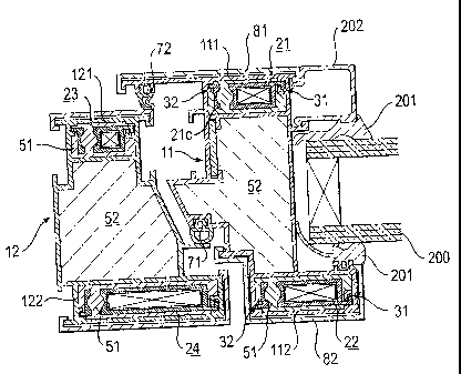
Referring to Fig. 1 and Fig. 4, a first embodiment of the invention is
described. Fig. 1 shows
profile members forming part of a frame profile and a window wing profile in a
cross section
perpendicular to the longitudinal direction of the respective profile members.
The right hand
side of Fig. 1 shows a plastic hollow profile 11 forming part of a window wing
in a cross sec-
tion perpendicular to the longitudinal direction. A double glass window pane
200 may be held
on/in the frame of the window wing via sealing/mounting elements 201, which
may also have a
different shape, and a glazing bead 202.
CA 02671304 2009-06-01
The plastic hollow profile 11 includes a hollow chamber 111 on the side shown
at the top of
Fig. 1 (interior side). The hollow chamber 111 is formed to accommodate a
reinforcement ele-
ment 21. Accommodation guides 31, 32 are formed in the accommodation 111
formed as the
hollow chamber. The accommodation guide 31 comprises a recess undercut towards
the inte-
rior of the accommodation 111. This undercut recess may, for example, be
defined by a rail
31 a having a hook-shaped cross section and an opposing side wall 31 b and an
outer wall 31 c of
the accommodation 111, as seen best from Fig. 4. The accommodation guide 32 is
formed on
the opposite side of the accommodation 111 as a recess that opens to the
interior of the ac-
commodation 111. This recess is defined by a linear bar 31d protruding
perpendicularly from
the corresponding side wall 32e of the accommodation 111, and an opposing wall
32f.
The aluminum hollow profile 21 includes a hollow chamber 21 a surrounded by
the aluminum
hollow profile from all sides in the cross section perpendicular to the
longitudinal direction.
The aluminum hollow profile 21 further includes a channel 21b extending
through the hollow
profile in the longitudinal direction, as shown in Fig. 1 and Fig. 4. This
channel is connected to
the interior of the accommodation 111 surrounding the aluminum hollow profile
21 via several
passages 21c (see Fig. 1).
The aluminum hollow profile 21 further includes a protruding rail 21 d. The
rail 21 d is formed
as a rail having a hook-shaped cross section and a shape that is complementary
to the undercut
recess of the accommodation guide 31 (within predetermined tolerances). A
protruding rail 21 e
is formed on the side of the aluminum hollow profile 21 opposite to the rail
21 d and has a
shape that is complementary to the recess of the accommodation guide 32
(within predeter-
mined tolerances). The rails 21 d and 21 e are formed on the aluminum hollow
profile 21 such
that they cooperate with the accommodation guides 31, 32 to accurately guide
and position the
aluminum profile 21 upon being inserted into the accommodation 111 and the
accommodation
guides 31, 32, as shown clearly in Fig. 4.
The accommodation 111 containing the aluminum hollow profile 21 inserted in
the above-
described manner is foam-filled with a foam 51. The foam 51 is thermosetting
foam having a
high density which fills the interior of the accommodation 111 surrounding the
aluminum hol-
low profile 21 and the channel 21b and the passages 21c of the aluminum hollow
profile 21.
6
CA 02671304 2009-06-01
The introduction of the foam 51 will be described later with respect to the
description of the
manufacturing of the reinforced plastic profile.
The plastic profile 11 includes a corresponding accommodation 112 on the side
opposite to the
accommodation 111 (the weather side). An aluminum hollow profile 22 is
inserted into the
accommodation 112. The accommodation 112 includes corresponding accommodation
guides
31, 32 which correspond to the accommodation 112 but have different external
dimensions. As
the accommodation 112, the accommodation guides 31, 32, and the aluminum
hollow profile
22 correspond to the above-described accommodation 111, aluminum hollow
profile 21, and
accommodation guides 31, 32, the description will not be repeated. Similarly,
high density
foam 51 is provided in the accommodation 112 in a corresponding manner.
The plastic hollow profile 11 further includes a hollow chamber 113.
Preferably, another rein-
forcement element 23 is arranged in the hollow chamber 113, if necessary,
position-accurately
relative to the external dimensions. The reinforcement element 23 is used for,
e.g., securely
screw-connecting fittings to be mounted on the outer surface of the plastic
hollow profile. Pref-
erably, the hollow chamber 113 is foam-filled at least partially (or
completely) with low den-
sity foam 52.
The cross section of the plastic hollow profile has a complex geometry with
undercuts and the
like for accommodating fitting and locking elements (not shown), seals 71, 72,
201, and other
elements such as the window bead 202, and for mounting decorative elements 81,
82. The
decorative elements 81, 82, for example, may be formed as aluminum covers
clipped onto the
profile. However, the decorative elements 81, 82 may also be made of other
materials such as
stainless steel, wood, plastics, etc.
The reinforced plastic profile of the above-described embodiment provides the
advantages with
respect to the design of the thermal properties, the mechanical properties,
the cross section, and
the surface and the color design described in the introduction. In the present
embodiment, the
aluminum hollow profiles 21, 22 are fixed to the plastic profile 11 by means
of high density
foam 5 l, wherein the plastic hollow profiles, in particular also the hollow
chamber 21 a, are
positioned position-accurately relative to the external contour of the plastic
profile 11 due to
the position accurate calibration of the external contour of the plastic
profile 11 and at least the
7
CA 02671304 2009-06-01
accommodation guides 31, 32 relevant to the positioning of the aluminum hollow
profiles 21,
22 in the manufacturing, which will be described later.
Now, as reinforced plastic profiles of the type specified above are connected
by means of cor-
ner connectors, these corner connectors may be slide inserted into hollow
chambers such as the
hollow chamber 21 a of the aluminum hollow profiles 21, 22, and the external
contours of the
plastic hollow profiles also align accurately due to the position accurate
calibration. Therefore,
expensive subsequent processing in the connecting by means of corner
connectors may be
minimized.
The frame profile shown in Fig. 1 including the plastic hollow profile 12 has
a structure similar
to the already described plastic hollow profile 11, and thus it will be
described briefly. Alumi-
num hollow profiles 23, 24 are position-accurately inserted into
accommodations 121, 122
having accommodation guides 31, 32, and are fixed position-accurately relative
to the external
contour of the plastic hollow profile 12 and, in addition, longitudinally
shear-resistantly by
means of high density foam 51. The plastic hollow profile includes another
hollow chamber
foam-filled partially (or completely) with low density foam 52. The remaining
features corre-
spond to those of the plastic hollow profile 11, and, therefore, their
description will not be re-
peated.
In the following, a method for manufacturing the reinforced plastic hollow
profile shown in
Fig. 1 and Fig. 4 will be described. EP 0 817 715 A1 and DE 199 21 458 A1,
respectively, de-
scribe methods and devices for manufacturing a hollow chamber profile that may
be used for
position-accurately calibrating individual parts or the hollow chamber profile
as a whole. The
plastic hollow profiles 11, 12 of the first embodiment are manufactured
according to corre-
sponding methods, wherein materials which are colorfast, lightfast, and/or
weatherproof are
selected, as required. In this manufacturing, the profiles are extruded, and
at least the outer
surfaces and the inner surfaces provided for positioning the reinforcement are
calibrated posi-
tion-accurately. Materials to be considered include rigid PVC, PA, PET, PPT,
PA/PPE, ASA
(reinforced or not reinforced), PA66GF, and other materials.
8
CA 02671304 2009-06-01
The reinforcement parts are preferably manufactured by aluminum extrusion. The
surface of
the reinforcements may be advantageously adapted to being bonded to the foam
by sand blast-
ing or priming.
The mounting of the reinforcement elements is performed by slide-inserting the
same in the
provided accommodation position. The reinforcement elements may be
longitudinally shear-
resistantly fixed in the hollow profile in a single foaming process, wherein
the foam is intro-
duced in the longitudinal direction through the channel 21 b and the
accommodation space sur-
rounding the aluminum hollow profile and the passages 21c. As described above,
high density
(preferably 0.3 to 0.6 kg/1) foam (e.g., thermosetting plastics such as PU as
a foam having a
corresponding density) is used for longitudinally shear-resistantly fixing the
reinforcement ele-
ments. Foams having low densities, and, as a result, especially low heat
conductances, may be
used for foam-filling portions for which a longitudinally shear resistant
connection between
reinforcement elements and the plastic hollow profile is not essential.
With the embodiment described above, arbitrary undercuttings at arbitrary
positions of the pro-
file are possible. The surface treatment of weather side or interior side
coverings made of alu-
minum may be performed independently of a foaming process, which is
advantageous, as the
foam does not tolerate burn-in temperatures. In addition to this advantage,
the described em-
bodiment provides a system having excellent mechanical properties, wherein the
reinforcement
profiles may be utilized for forming corner connections by means of corner
connectors, and, at
the same time, the subsequent processing that is necessary is minimized. The
embodiment fur-
ther allows for the use of foams having different densities, and the resulting
optimization of
heat conducting properties. It is particularly advantageous to divide the
foaming portions such
that high density foams are utilized for longitudinally shear-resistantly
connecting the rein-
forcement, and low density foam having particularly low lambda values is
utilized for foam-
filling the main hollow space.
Furthermore, the advantages described in the introduction are provided.
Referring to Fig. 2, in the following a second embodiment is described. The
embodiment
shown in Fig. 2 differs from the first embodiment shown in Fig. 1 only with
respect to parts of
the frame profile. As seen from the upper left side of Fig. 2, a plastic
hollow profile 13 forming
9
CA 02671304 2009-06-01
the frame profile includes an embodiment of the accommodation 122,
accommodation guides,
and aluminum hollow profile 24 corresponding to the first embodiment on the
side shown at
the bottom of Fig. 1(the weather side), which will not be described further.
No hollow cham-
ber corresponding to the accommodation 121 is formed on the side at the top of
Fig. 1, instead,
an accommodation 131 for an aluminum hollow profile 25 is formed on the
outside of the plas-
tic hollow profile 13. The accommodation 131 includes accommodation guides 33
having a
shape corresponding to the accommodation guide 31.
An aluminum hollow profile 25 includes a first portion 25f in which a hollow
chamber 25a
corresponding to the hollow chamber 21 a is formed. As in the aluminum profile
21, a channel
25b that also extends in the longitudinal direction is formed. However, the
channel 25b in-
cludes passages 25c only to one side. This side is the side facing the plastic
hollow profile 13
in the assembled state. Parallel protruding rails 25g having hook-shaped ends
on the sides op-
posite the first portion 25f extend from the first portion 25f. Rails 25h also
having a hook-
shaped cross section extend from the hook-shaped ends and are complementary to
the undercut
recesses of the accommodation guides 33 (with predetermined tolerances)
(similar to the ac-
commodation guides 31 and the corresponding rails 21d of the first
embodiment). The alumi-
num hollow profile is foam-attached to the plastic hollow profile 13 to
longitudinally shear-
resistantly and position-accurately connect the aluminum hollow profile 25 to
the plastic hol-
low profile 13, with the foam being distributed in the longitudinal direction
via the channel 25b
and the passages 25c and the space between the aluminum hollow profile 25 and
the plastic
hollow profile 13. As in the first embodiment, high density foain 51 is used
for foam-attaching.
Obviously, a position-accurate and longitudinally shear-resistant connection
of the aluminum
hollow profile 25 to the plastic hollow profile 13 by means of foam-attaching
may be achieved
with a correspondingly calibrated form of the outer contour and the
accommodation guides 33
of the plastic hollow profile 13.
Referring to Fig. 3, a third embodiment is described. The third embodiment
differs from the
first embodiment in that no accommodation guides 31, 32 are provided in the
accommodations
141, 142, 151, 152 of the plastic hollow profiles 14, 15. Instead, the
aluminum hollow profiles
26, 27, 28, 29 include protruding rails on the outside of the aluminum hollow
profiles which, in
combination with the position-accurately calibrated inner surfaces of the
accommodations 141,
CA 02671304 2009-06-01
142, 151, 152, provide accurate guiding and positioning of the aluminum hollow
profiles in-
serted into the accommodations.
As in the first and second embodiments, the aluminum hollow profiles 26, 27,
28, 29 are fixed
position-accurately and longitudinally shear-resistantly in the accommodations
141, 142, 151,
152 using high density foam 51.
The remaining features of the third embodiment correspond to the corresponding
features of
the first and second embodiments. Therefore, the description will not be
repeated.
In all embodiments, the method of manufacturing described with respect to the
first embodi-
ment may be used for manufacturing the plastic hollow profile. In all
embodiments, in which
the aluminum hollow profiles are foam-embedded or foam-attached, the method
described with
respect to the first and second embodiments, respectively, may be applied.
The plastic hollow profiles 11 to 15 described herein each have a single inner
hollow chamber
filled with low density foam 52. The plastic hollow profiles may include
several chambers,
which may be filled with high or low density foams fully or partially,
depending on the re-
quired arrangement.
All embodiments have in common that the hollow chambers of the aluminum hollow
profiles
may be positioned position-accurately such that the use of corresponding
hollow chambers for
forming corner connections by means of corner connectors may be utilized.
It will be apparent that, as an alternative or in addition to corner
connectors, the corresponding
connection may also be formed differently, for example, by fusing the plastic
hollow profiles.
In this case, the longitudinally shear-resistant and position-accurate
arrangement of the alumi-
num hollow profiles is also advantageous, because, on the one hand, the
mechanical properties
may be improved, and, on the other hand, subsequent processing due to
projections or the like
may be avoided.
11
CA 02671304 2009-06-01
The appearance of the described profiles may be designed, on the one hand, by
correspond-
ingly choosing the plastic materials, and, on the other hand, by attaching
elements made of
aluininum or other materials.
It is explicitly stated that all features disclosed in the description and/or
the claims should be
regarded as separate and independent of each other for the purpose of original
disclosure as
well as for the purpose of restricting the claimed invention, independent of
the combination of
features in the embodiments and/or the claims. It is explicitly stated that
all indications of
ranges or of groups of units disclose any possible intermediate value or sub-
group of units for
the purpose of original disclosure as well as for the purpose of restricting
the claimed inven-
tion, especially also as a limit of a range indication.
12