Note : Les descriptions sont présentées dans la langue officielle dans laquelle elles ont été soumises.
CA 02672545 2009-06-12
- 1 -
DESCRIPTION
APPARATUS AND METHOD FOR CONTROLLING ELECTRIC COMPRESSOR
Technical Field
The present invention relates to an apparatus and
method for controlling an electric compressor
constituting an air conditioner.
Background of Art
Conventionally, in an automotive air conditioner,
the driving force of an automotive engine has been used
to drive a compressor for compressing a refrigerant.
However, with the recent practical use of electric
vehicles and the like, what is called an electric
compressor, in which an electric motor is used as a
driving source for the compressor, has been developed.
In such an electric compressor, since the driving
torque produced by the motor is lower than that produced
by an engine, if the pressure difference of refrigerant
between the inlet side and the outlet side of the
compressor is large especially at the time of actuation,
there is a possibility that the compressor cannot be
actuated. The reason for this is that the motor load
that tends to actuate the compressor becomes excessive
because of the large pressure difference, so that, in a
CA 02672545 2009-06-12
- 2 -
motor drive control circuit, an overcurrent protecting
function for protecting the motor is triggered.
To solve this problem, a technique has been proposed
that there is provided a differential pressure sensor for
detecting the pressure difference between the inlet side
and the outlet side of the compressor, and a threshold
value for judging whether or not the current flowing in
the motor when the compressor is actuated is changed
according to the detection value of the differential
pressure sensor, or a voltage applied to the motor is
controlled (for example, refer to Patent Document 1).
Patent Document 1: Japanese Patent Laid-Open No. 2006-
29342
Disclosure of the Invention
Problems to be Solved by the Invention
However, in the technique proposed in Patent
Document 1, the control is complicated, and the
differential pressure sensor is needed, which leads to an
increase in weight, cost, and assembling time caused by
the increase in the number of parts of electric
compressor. Also, if the differential pressure sensor
fails, the function cannot be performed, which provides
room for improvement in reliability.
Also, depending on the operating condition at the
time when the air conditioner is stopped, the pressure
difference of refrigerant between the inlet side and the
CA 02672545 2009-06-12
- 3 -
outlet side of the compressor is sometimes large.
Further, in the case where a long period of time has
elapsed after the air conditioner has been stopped, the
refrigerant gas on the outlet side turns from a gas state
to a liquid state, so that liquid compression may provide
motor overload. In such a case, in the conventional
technique, much time is required from when the compressor
is actuated to when the air conditioner is operated
normally. In particular, the automotive air conditioner
has a need for the compressor to be actuated rapidly
because it is to be desired that the air conditioner be
operated strongly immediately after the startup of the
compressor. Therefore, in any case, it is desired to
actuate the compressor rapidly. In this respect, there
is room for further improvement.
The present invention has been accomplished to solve
the above technical problems, and accordingly an object
thereof is to provide an apparatus and method for
controlling an electric compressor, in which an electric
compressor can be actuated rapidly through a simpler and
lower-cost configuration while achieving reduction in
weight, cost, and assembling time of the electric
compressor.
Means for Solving the Problems
An apparatus for controlling an electric compressor
of the present invention accomplished to achieve the
CA 02672545 2009-06-12
- 4 -
above object is an apparatus for controlling an electric
compressor which drives the compressor constituting an
air conditioner by using a motor, characterized in that
processing performed by the apparatus includes processing
for avoiding motor overload caused by a pressure
difference of a refrigerant between the inlet side and
the outlet side of the compressor by keeping the number
of revolutions of the motor not higher than a preset
first number of revolutions when the actuation of the
motor is started; and processing for increasing the
number of revolutions of the motor to a second number of
revolutions not lower than the first number of
revolutions.
At this time, in the processing for avoiding motor
overload caused by the pressure difference of the
refrigerant, by keeping the number of revolutions of the
motor not higher than the first number of revolutions,
the refrigerant liquefied on the outlet side of the
compressor can be pushed out. Thereby, even in the case
where the pressure difference is large, the motor can be
actuated.
In the processing for avoiding motor overload caused
by the pressure difference of the refrigerant, it is
preferable that a rate of rise S1 of the number of
revolutions of the motor be set lower than a rate of rise
S2 of the number of revolutions of the motor in the
processing for increasing the number of revolutions of
CA 02672545 2009-06-12
- 5 -
the motor to the second number of revolutions. The rate
of rise Sl includes zero. Specifically, in the
processing for avoiding motor overload caused by the
pressure difference of the refrigerant, a time period for
which the number of revolutions of the motor is kept low
is provided.
It is preferable that the apparatus further perform
processing for monitoring whether a current supplied to
drive the motor exceeds a preset threshold value.
Immediately after the actuation of the motor has
been started, the number of revolutions of the motor can
be increased at a rate of rise S3 higher than the rate of
rise Sl of the number of revolutions of the motor in the
processing for avoiding motor overload caused by the
pressure difference of the refrigerant. Also, the
configuration may be such that, in the processing for
monitoring the current supplied to drive the motor, when
the current exceeds the preset threshold value, the
processing shifts to the processing for avoiding motor
overload caused by the pressure difference of the
refrigerant.
That is to say, in the normal time, the compressor
is actuated by increasing the number of revolutions of
the motor at a high rate of rise S3, and when overcurrent
flows in the motor, the processing for avoiding motor
overload caused by the pressure difference of the
refrigerant is performed. Thereby, in the case where the
CA 02672545 2009-06-12
- 6 -
pressure difference is small, the compressor can be
actuated rapidly by increasing the number of revolutions
of the motor at a high rate of rise S3.
In the case where the air conditioner is mounted on
a vehicle, the present invention can be applied
especially effectively.
In the present invention, there can also be provided
a method for controlling an electric compressor which
drives the compressor constituting an air conditioner by
using a motor, characterized by including a time period
for keeping a rate of rise of the number of revolutions
of the motor not higher than a preset rate of rise Si
when the actuation of the motor is started; and a time
period for increasing the number of revolutions of the
motor to a preset number of revolutions by taking the
rate of rise of the number of revolutions of the motor as
a rate of rise S2 not lower than the rate of rise Sl.
Advantages of the Invention
According to the present invention, in actuating the
motor of the electric compressor, even in the case where
a large pressure difference arises between the inlet side
and the outlet side of the compressor, by actuating the
motor at a low number of revolutions, such action as to
push out the liquefied refrigerant can be accomplished,
and the motor can be actuated. As a result, the electric
compressor can be actuated surely. Moreover, by changing
CA 02672545 2009-06-12
- 7 -
the rate of rise of the number of revolutions of the
motor from Sl to S2, the number of revolutions of the
motor can be caused to reach the required number of
revolutions as early as possible while surely performing
the actuation, so that the air conditioner can be
actuated rapidly.
In addition, the above-described configuration can
achieve effects of reduction in weight, cost, and
assembling time and improvement in reliability resulting
from the reduction in the number of parts because a
differential pressure sensor need not be used.
Brief Description of the Drawings
Figure 1 is a block diagram showing a schematic
configuration of an electric compressor in accordance
with an embodiment;
Figures 2A, 2B and 2C are graphs showing pattern
examples of changes of number of revolutions of a motor
at the time when the motor is actuated in an actuation
control section; and
Figure 3 is a flowchart showing a flow of processing
at the time when the motor is actuated in an actuation
control section.
Description of Symbols
... electric compressor, 11 ... compressor body,
lla ... inlet side, llb ... outlet side, 12 ... motor,
CA 02672545 2009-06-12
- 8 -
13 ... control board, 14 ... switching element, 15 ...
control unit, 17 ... current detecting circuit, 20 ...
overcurrent protecting section, 21 ... actuation control
section
Best Mode for Carrying Out the Invention
The present invention will now be described in
detail based on an embodiment shown in the accompanying
drawings.
Figure 1 is a block diagram for explaining a
configuration of an electric compressor 10 for an
automotive air conditioner in accordance with the
embodiment.
As shown in Figure 1, the electric compressor 10
includes a compressor body 11 for compressing a
refrigerant, a motor 12 for driving the compressor body
11, and a control board 13 for rotating the motor 12.
The control board 13 includes a switching element 14
for converting a voltage supplied from a dc power source
into ac voltage, a control unit 15 consisting of a
microcomputer for controlling the operation of the
switching element 14, and a gate circuit 16. When the
gate circuit 16 is driven by the control of the control
unit 15, and the drive signal thereof is input to the
switching element 14, the switching element 14 is
operated. Thereby, the voltage supplied from the dc
power source is applied to the motor 12 of the electric
CA 02672545 2009-06-12
- 9 -
compressor 10 as a three-phase alternating current, by
which the motor 12 is rotationally driven.
The control board 13 includes a current detecting
circuit 17 for detecting a current supplied to the
switching element 14. The control unit 15 monitors a
current supplied from the switching element 14 to the
motor 12 based on a current value detected by the current
detecting circuit 17. To prevent overcurrent from being
supplied to the motor 12 when the current value exceeds a
preset detection value, the control unit 15 has, as a
function, an overcurrent protecting section 20 for
stopping the supply of current to the motor 12.
Also, the control unit 15 has, as a function, an
actuation control section 21 for controlling a current
supplied to the switching element 14 when the motor is
actuated.
In the actuation control section 21, a preset
current is supplied to the switching element 14 to
actuate the motor 12 (hereinafter, referred to as a
normal actuation mode) When, in the overcurrent
protecting section 20, the current supplied to the motor
12 does not exceed the threshold value, and the motor 12
is actuated while it is not judged that the current is
overcurrent, the motor 12 is rotated at a predetermined
number of revolutions at the time of steady operation to
compress the refrigerant by the compressor body 11. On
the other hand, when, in the overcurrent protecting
CA 02672545 2009-06-12
- 10 -
section 20, as a result of actuation, it is judged that
the cuirent supplied to the motor 12 exceeds the
threshold value and is overcurrent, the actuation of the
motor 12 is suspended, and a lower current is supplied to
restart the motor 12 (hereinafter, referred to as a
restart mode). When the motor 12 is restarted, the
supplied current is increased gradually by being changed
stepwise or linearly.
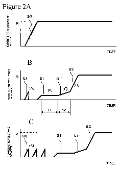
Figures 2A, 2B and 2C show examples of changes of
number of revolutions of the motor 12 at the time when
the motor is actuated, which is caused by the above-
described control in the actuation control section 21.
As shown in Figure 2A, at the normal time, when a
current is supplied to the switching element 14 to
actuate the motor 12 in the normal mode, the number of
revolutions of the motor 12 increases until reaching a
predetermined number of revolutions R at the time of
steady operation. The rate of rise of the number of
revolutions at this time is taken as S3.
When the pressure difference between an inlet side
lla and an outlet side llb of the compressor body 11 is
large, as shown in Figure 2B, when the motor 12 is
actuated in the normal mode, the number of revolutions of
the motor 12 does not increase because the resistance in
the compressor body 11 at the time when the compressor
body 11 is going to compress the refrigerant is high due
to the pressure difference. In process of increasing the
CA 02672545 2009-06-12
- 11 -
number of revolutions, the overcurrent protecting section
20 detects overcurrent, and the actuation of the motor 12
is suspended (refer to (A) in Figure 2B).
Subsequently, in the actuation control section 21,
the motor 12 is restarted in the restart mode. At this
time, by changing the supplied current stepwise, the
number of revolutions of the motor 12 is increased
gradually. In this embodiment, in a time period (first
time period) from when the restart mode is started to
when predetermined time tl has elapsed, a current is
supplied so that the rate of rise S1 of the number of
revolutions of the motor 12 is made not higher tran the
aforementioned rate of rise S3, and the number of
revolutions of the motor 12 is kept not larger than a
fixed number of revolutions (first number of revolutions)
(refer to (B) in Figure 2B). The purpose in this time
period is to rotate the motor 12 in the state in which
the number of revolutions is kept to push out a
refrigerant that may be in a liquid state on the outlet
side llb of the compressor body 11.
After the first time period has finished, in a time
period (second time period) until preset time t2 has
elapsed, a current is supplied so that the number of
revolutions of the motor 12 increases at a rate of rise
Sl' lower than the rate of rise S3 in the normal mode
(refer to (C) in Figure 2B). The purpose in this time
period is to completely push out the refrigerant in a
CA 02672545 2009-06-12
- 12 -
liquid state on the outlet side llb of the compressor
body 11 and to obtain the number of revolutions at the
time of steady operation in a shorter period of time.
After the second time period has finished, a current is
supplied so that the number of revolutions of the motor
12 increases at the rate of rise S2 that is similar to
the rate of rise in the normal mode until reaching the
number of revolutions at the time of steady operation
(second number of revolutions) R (refer to (D) in Figure
2B).
That is to say, in the first time period, the
refrigerant that may be in a liquid state is pushed out,
and subsequently, in the second time period, the number
of revolutions of the motor 12 is increased gradually in
such a state that the current supplied to the motor 12 is
not overcurrent. In the third time period, after the
pressure difference has become equivalent to '-hat at the
normal start time, the number of revolutions of the motor
12 is increased rapidly at the rate of rise similar to
that in the normal mode.
Needless to say, the pattern of change in the number
of revolutions of the motor 12 in the restart mode shown
in Figure 2B is only an example. If the motor 12 can
surely be actuated from a state in which a pressure
difference is present and moreover the number of
revolutions can reach the predetermined number of
CA 02672545 2009-06-12
- 13 -
revolutions as early as possible, any pattern may be
adopted.
Also, as shown in Figure 2C, in the case where
overcurrent is detected when the motor 12 is actuated in
the normal mode, after the actuation in the normal mode
has been tried a plurality of times, the motor 12 may be
actuated in the restart mode.
Hereunder, a flow of processing for carrying out the
above-described control in the actuation control section
21 is explained with reference to Figure 3.
As shown in Figure 3, when a command of actuation is
input to the control unit 15 from a host control circuit
for controlling the entire operation of the automotive
air conditioner, in the control unit 15, the actuation
processing of the electric compressor 10 is started. At
this time, the control unit 15 receives a command of a
required number of revolutions of the motor 12 (that is,
the predetermined number of revolutions R at the time of
steady operation) from the host control circuit.
First, in the control unit 15, a current value in
accordance with the required number of revolutions of the
motor 12 commanded from the host control circuit is set
based on a preset table (Step S101). Along with this, a
threshold value for overcurrent protection corresponding
to the set current value is set.
Next, in the actuation control section 21 of the
control unit 15, a current having a magnitude having been
CA 02672545 2009-06-12
- 14 -
set in Step S101 is supplied to the switching element 14
to actuate the motor 12 in the normal mode (Step S102).
After the motor 12 has been actuated, while
monitoring whether overcurrent is detected in the
overcurrent protecting section 20 (Step S103), the
control waits until the number of revolutions of the
motor 12 reaches the required number of revolutions (Step
S104), and when the required number of revolutions
(number of revolutions R) is reached, the actuation
processing is finished, thereafter the control going to
steady operation.
After the motor 12 has been actuated, if overcurrent
is detected in the overcurrent protecting section 20 in
Step S103, the control returns to Step S102, and the
motor 12 is actuated again in the normal mode. This
actuation of the motor 12 in the normal mode is repeated
until preset times (for example, three times in this
embodiment; a pattern corresponding to Figure 2C) are
reached (Step S105).
If the number of revolutions of the motor 12 reaches
the required number of revolutions without detecting
overcurrent in the overcurrent protecting section 20
during the time when the actuation in the normal mode is
repeated until the preset times are reached (Step S103,
S104), the control goes to steady operation as it is.
In the case where overcurrent is detected in the
overcurrent protecting section 20 even if the actuation
CA 02672545 2009-06-12
- 15 -
in the normal mode is repeated until the preset times are
reached, the control goes to actuation in the restart
mode.
For this purpose, first, a current value
corresponding to the pattern of change in the number of
revolutions of the motor 12 in the restart mode (refer to
Figures 2B and 2C) is set (Step S106) . Along wLth this,
a threshold value for overcurrent protection
corresponding to the set current value is set.
Next, in the actuation control section 21 of the
control unit 15, a current having a magnitude having been
set in Step S106 is supplied to the switching element 14
to actuate the motor 12 in the restart mode (Step S107).
At this time, to change the number of revolutions of the
motor 12 in a pattern as shown in Figure 2C, in the
actuation control section 21, a current having a
predetermined magnitude is supplied to the switching
element 14 in each of the first, second, and third time
periods while monitoring the elapsed time by using a
timer.
After the motor 12 has been actuated in the restart
mode, while monitoring whether overcurrent is detected in
the overcurrent protecting section 20 (Step S108), the
control waits until the number of revolutions of the
motor 12 reaches the required number of revolutions (Step
S104), and when the required number of revolutions is
reached, the control goes to steady operation.
CA 02672545 2009-06-12
- 16 -
On the other hand, after the motor 12 has been
actuated, if overcurrent is detected in the overcurrent
protecting section 20 in Step S108, it is judged that any
trouble has occurred in the compressor body 11 for any
cause other than pressure difference, the actuation of
the motor 12 is suspended, and the occurrence of trouble
is notified to the host control circuit. Needless to say,
at this time as well, when overcurrent is detected in
Step S108, the actuation of the motor 12 in the restart
mode may be repeated until the preset times are reached.
By actuating the motor 12 in this manner, even when
a pressure difference arises between the inlet side lla
and the outlet side lib of the compressor body 11, the
motor 12 is actuated in the restart mode at a number of
revolutions lower than that in the normal mode, by which
the motor 12 can be actuated. As a result, even in the
case where the refrigerant has been liquefied, for
example, on the outlet side llb of the compressor body 11,
such action as to push out the liquefied refrigerant can
be performed immediately after the compressor body 11 has
been actuated, so that the electric compressor 10 can
surely actuated.
Moreover, in the restart mode, by increasing the
number of revolutions of the motor 12 while changing
stepwise or linearly, the number of revolutions of the
motor 12 can be caused to reach the required number of
revolutions as early as possible while surely performing
CA 02672545 2009-06-12
- 17 -
the actuation, so that the air conditioner can be
actuated rapidly.
In addition, the above-described configuration
achieves effects of reduction in weight, cost, and
assembling time and improvement in reliability resulting
from the reduction in the number of parts because a
differential pressure sensor need not be used.
In the above-described embodiment, the examples of
patterns of change in the number of revolutions of the
motor 12 in the restart mode are shown in Figures 2A, 2B
and 2C. However, it is a matter of course that any
pattern other than those shown in Figures 2A, 2B and 2C
may be used, or a plurality of kinds of patterns may be
used by being changed over.
Further, the configuration may be such that the
operating conditions (the operation/stop state etc. of
the compressor body 11) at the time when the air
conditioner is previously stopped, the time elapsed from
the stopping, and the like are stored, and the pattern of
change in the number of revolutions of the motor 12 in
the restart mode is changed over according to the stored
operating conditions.
Also, in the above-described embodiment, the
configuration is such that when the actuation in the
normal mode becomes a failure, the actuation shifts to
the restart mode. However, the present invention is not
limited to this configuration. The motor 12 can be
CA 02672545 2009-06-12
- 18 -
actuated in a pattern similar to the restart mode, for
example, as shown in Figure 2B from the first actuation
time.
Besides, regarding the configuration, the control
method, and the like of the electric compressor 10, the
configurations described in the above embodiment can be
selected or can be changed appropriately without
departing from the spirit and scope of the present
invention.