Note : Les descriptions sont présentées dans la langue officielle dans laquelle elles ont été soumises.
CA 02673890 2009-07-24
1
REUSABLE SHOPPING BAG
Related Applications
[0001] The present application claims priority from US Application No.
61/145,383, filed
January 16, 2009, and US Application No. 61/083,73 1, filed July 25, 2008. The
disclosure of
these prior applications is herein incorporated by reference.
Field of the Invention
[0002] The present application relates to bags of the type used for collecting
and transporting
items, such as products purchased in a grocery or retail store.
Background of the Invention
[0003] During recent times, plastic bags have replaced paper bags in the
United States and
around the world for transporting groceries and retail products purchased at a
store to the home
or similar location. In many cases, these disposable plastic bags are T-shirt
type bags, having
laterally spaced handles integrally formed with the bag and extending upwardly
from opposite
sides of an open mouth. T-shirt bags are typically retained in stacks and
mounted on a rack
system within the store. A T-shirt bag rack system allows bags to be supported
for loading and
to be consecutively removed from the stack. An example of a T-shirt bag
construction is
illustrated in US 5,335,788. An advantageous T-shirt bag rack system is
disclosed in US
4,676,378. These prior patents are commonly assigned with the present
application and the
disclosure therein is herein incorporated by reference.
[0004] Although there are many advantages in a retail and grocery store
environment to
using a system of disposable bags supported on a rack, certain environmental
concems have
directed some individuals to utilize reusable or multi-use bags for purposes
of carrying groceries
and retail items. The reusable bags are typically lightweight and are taken to
the store by the
consumer and handed to the counter attendant during packing of the purchased
items. The
reusable bags are sufficiently strong to permit repeated transport of
purchased items without
damage or breakage.
CA 02673890 2009-07-24
2
Brief Summary of the Invention
[0005] The present invention is a reusable bag having a defined volume and
various elements
for supporting the bag on a typical T-shirt bag rack system. The rim of the
open end of the bag
preferably includes a loop to secure the bag to a central support hook on the
rack. Apertures are
provided in the side panel of the bag to receive the extending arms of the
rack system, such that
the arms support the side panels and maintain the bag open during loading. The
apertures may
direct the rack arms into channels formed within the upper rim of the bag.
[0006] In addition to or as an alternate structure, the present invention
contemplates a
reinforced bottom panel. A two-ply section is preferably provided on the
bottom panel of the
bag having an extension portion that wraps around the edge of the bottom wall
and at least
partially extends up one or more of the front, rear, or side panels of the
bag. A portion of the
bottom wall may further be integrally formed with at least one of the panels.
100071 The present invention further takes the form of a system for loading
purchased
products or the like within a reusable bag, which is supported on a support
rack. In addition, the
rack may further include a support for one or more smaller bags. The system
would then permit
the placement within the smaller bags of products that are desired to be
separated from other
items, which are then positioned within the relatively larger, reusable bag.
Brief Description of the Drawinas
[0008] Without restricting the full scope of the present invention, various
preferred forms of
the invention and its related articles are illustrated in the following
drawings.
[0009] Fig. 1 shows a perspective view of T-shirt bag rack system for
supporting a bag,
which is outlined in phantom.
[0010] Fig. 2 shows a perspective view of an embodiment of a reusable bag as
contemplated
by the present invention mounted on the rack system of Fig. 1.
[0011] Fig. 3 shows an exploded view of the various constituent parts of the
reusable bag
embodiment as shown in Fig. 2.
[0012] Fig. 4 shows a partial assembly of a further embodiment of a reusable
bag as
contemplated by the present invention.
[0013] Figs. 5a and 5b show a partial assembly of a portion of a further
embodiment of a
reusable bag as contemplated by the present invention.
CA 02673890 2009-07-24
3
[00141 Fig. 6 shows a side elevation of a still further embodiment of a
reusable bag as
contemplated by the present invention.
[0015] Fig. 7 shows a perspective view of an additional embodiment of a
reusable bag as
contemplated by the present invention.
[0016] Fig. 8 shows a series of perspective views of the bag embodiment of
Fig. 7 wherein
the bag is folded and a display tag is attached thereto.
Detailed Description of the Drawinjzs
[0017] In the drawings, wherein like numerals indicate like elements, there
are shown
various embodiments of a multi-use or reusable bag. It is contemplated that
the reusable bag of
the present invention will be positioned on a T-shirt bag rack system. There
is shown in Fig. 1
an example of a rack system of the type that may be utilized as part of the
contemplated
invention. The rack is generally in the form of that shown and described in US
Publication No.
US 2007/0186515, which is commonly assigned with the present application and
which is herein
incorporated by reference. The rack is identified by the numeral 12. The
position of a bag on
the rack is shown in phantom in Fig. 1.
[0018] The rack 12 as shown typically supports a series of plastic single-use
type bags
formed within a stack (not shown). A scale 14 is provided below the bag
support surface 16.
Arms 18, 20 are provided on opposite sides of the rack 12 and are attached to
a supporting
framework 22 forming the rear of the rack. The framework 22 is secured to the
base 16 and
scale 14 to form a substantially rigid structure. A central hook 24 is
provided on the framework
22 for support of a bag stack in the typical use of the rack 12. The purpose
and function of the
central hook 24 may be similar to that disclosed in US 5,845,779, which is
herein incorporated
by reference. An accumulator display 26 is provided on the upper cross member
of the support
frame 22. The function of the accumulator display 26, which is connected to
the scale 14, is
described in US 2007/0186515. It is contemplated that the bag of the present
invention may take
the advantage of the accumulator display 26 portion of the rack 12, when
provided.
[0019] In Fig. 2, there is shown an embodiment of a bag 10 of the invention
positioned on
the rack 12. In addition, a series of separator bags 28 are supported on a
side hook 29 on the side
of the frame 12. The separator bags 28 are used to retain individual or bulk
items and maintain
them separate from other items placed in the bag 10. The separator bags 28 can
be in the form of
CA 02673890 2009-07-24
4
a typical produce plastic bag or can be reusable containers having support
loops or the like for
attachment to the side hook 29.
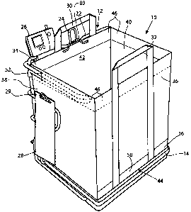
[0020) As shown in Figs. 2 and 3, the bag 10 includes handles 30, 32
respectively attached to
a rear panel 34 and a front panel 36. Side panels 38, 40 are provided and
connect the rear panel
34 and front panel 36, thereby defining an interior volume 42 within the bag
10. The interior
volume 42 remains open at the top and is enclosed on the bottom by a bottom
pane144. Along
the top edge of the rear pane134, side panels 38, 40, and front pane136 is a
reinforcement rim 46.
The rim 46 is preferably a hem formed from material of the associated panel
that is folded over
and stitched (or otherwise adhered) to the panel to form a finished edge. A
channel is formed by
the rim 46, preferably at least along the side panels 38, 40. The channel 46
extends between the
rim 46 and the material of the adjacent panels 38, 40.
[00211 An opening 52 is provided in the rim 46 portion of the side panel 40
(with a similar
opening formed in opposing side panel 38). The openings 52 provide access to
the channel
formed by the rim 46 and panels 40, 38. Handles 30, 32 extend along the front
panel 36 (and
rear panel 34) and are preferably stitched (or otherwise attached) to the bag
for substantially its
entire height. Alternativety, the handles 30, 32 may be stitched to rim
portions 46 of the rear and
front panels 34, 36. Such a construction is shown in Fig. 7 and would be
typically used if the
material of the panels is sufficiently strong to withstand the operational
stress experienced during
carrying of a filled bag by its handles 30, 32. In the embodiment of Figs. 2
and 3, the attachment
of the handles 30, 32 includes additional reinforcement due to extension of
the handles 30, 32
along the panels 36, 42. This structure further strengthens the front and rear
panels 36, 42 due to
the additional material secured to the panel surfaces. Other variations of the
handles are possible,
including handles formed from a continuous loop that wraps under the bottom of
the bag,
handles that are integrally formed with the body of the bag, or other forms.
[00221 In Fig. 3, the constituent parts of the bag 10 of Fig. 2 are shown. A
first panel l0A
encompasses the two side panels 38 and 40 of the finished bag, along with the
associated hem
flaps 54 fold inward against the side panels along line 53 to form the rims 46
on the side panels
38, 40. Extension panels 50 project on opposite sides of the first bottom
pane144A transverse to
the extension of the side panels 38 and 40. Openings 52 are formed in the side
panels 38, 40,
adjacent the hem fold line 53. When the flaps 54 are folded inward to form the
rim 46 (shown in
CA 02673890 2009-07-24
Fig. 2), the openings 52 provide access to the channels for receiving the arms
18, 20 of the rack
12.
[0023] A second panel lOB incorporates the rear panel 34 and front panel 36,
as well as a
second bottom panel 44B. Hem flaps 55 are provided on the ends of the front
and rear panels 34,
36, opposite the second bottom panel 44B. The hem flaps 55 are similar to
flaps 54 and are
defined by fold lines 56. Handles 30, 32 are separate members that are
attached to the front and
rear panels 34, 36 when the bag 10 is assembled. A loop 80 is also added along
the rim 46 of the
rear pane134.
[0024] Assembly of the first bag panel 10A to the second bag panel l OB is
accomplished by
overlaying the two bottom panels 44A and 44B, such that the rear panel 34 and
the front panel
36 extend transverse to the side panels 38 and 40. The side edges of the
various panels are then
brought together to form a super imposed seam and adhered by sewing, glue,
heat, etc. A
reinforcement tape or binding may be applied over the formed seam between the
adjacent panels.
The extension flaps 50 on the first bag panel l0A are secured to the rear
pane134 and front panel
36, adjacent the bottom pane144A. Securing the extensions 50 to the panels 34,
36 may be in
any manner desired, with a lap seam preferred. The handles 30, 32 may be
formed as flattened
tubular members with stitching on each side. The handles 30, 32 are attached
to the respective
front panel 34 and rear pane136, preferably by stitching. Reinforcement flaps
46 are formed on
each pane134, 36, 38, and 40 by folding the hem flaps 54, 55 and securing them
to the panels.
[0025] As shown in Fig. 2, an assembled bag 10 is supported on the rack 12.
The loop 80 is
provided on the rim 46 of the rear panel 34 and is sufficiently long to be
positioned over the
central hook 24 on the rack 12. The side arms 18, 20 are inserted into the
openings 52, such that
the arms 18, 20 move into the channel formed in the rim 46 of the side panels
38, 40. In this
position, the bag 10 is supported on two sides and in the rear. This support
of the bag by the rack
12 stabilizes the flexible side panels and maintains the bag in an open
condition for receipt of
groceries or other items. An inner flap (not shown) may be provided in the bag
10 that forms a
pocket for supporting taller items, such as bottles or bread. The flap is
preferably in the form of
an elongated loop, attached to the back panel and a side panel.
[0026] Fig. 4 shows an alternate construction for a reinforced bottom panel
64. In this
construction, a rear panel 60 is attached to a front panel 62 by means of
overlapping bottom
panels 64 and 66. Extension flaps 68 and 69 are provided adjacent the
respective overlapping
CA 02673890 2009-07-24
6
panels 64 and 66. The extension flaps 68, 69 are secured to the corresponding
rear panel 60 and
front panel 62. This construction creates a secure, two ply bottom wall for
the bag, with the
panels 60, 62 replacing the rear panel 34 and front panel 36 in the
embodiments shown in Figs. 2
and 3. Alternatively, the panels 60, 62 may serve as replacements for the side
panels 38 and 40.
The additional bag panels (not shown in Fig 4.) are secured to the side edges
of the illustrated
panels 60, 62 to complete the bag construction.
[0027] In Figs. SA and 5B, another bag assembly is illustrated, with bag
panels 70 and 72
incorporating bottom panels 74 and 76, respectively. No extension panels are
incorporated into
this construction. The overlapping bottom panels 74 and 76 are secured
together along the
bottom edge seams 78. The panels 70 and 72 may be used as replacements for the
rear panel 34
and front panel 36 of the embodiments of Figs. 2 and 3, or may be replacements
for the side
panels 38, 40.
[0028] In the embodiment shown in Fig. 6, tabs 48 are added adjacent the
opening 52. The
tabs 48 are separate portions of T-shaped members 58 having a base portion 58A
and a fold
portion 58B, which are positioned transverse to one another. The base member
58A is
positioned under the hem flap (54) and stitched within the rim 46 at the top
of the side panel 38.
The fold portion 58B is folded along line 59 and the two portions are adhered
(stitched) together.
The fold portion 58B extends through the opening 52 to define the tab 48. The
fold portion S8B
is preferably secured to one edge of the opening 52, with the remainder of the
opening reinforced
by stitching or the like. The openings 52 provide access into the channel
formed by the rim 46 at
the top of the side panels 38, 40. The tabs 48 provide a gripping member for
enlarging the
opening 52 to ease access of the arms 18, 20 (Fig. 1) into the channel of hem
46.
[0029] In Figs. 7 and 8, a further embodiment of a bag assembly is shown
having side panels
38, 40, each having an attached skirt portion 90. The skirt portion 90 as
illustrated includes an
open end 92 facing the rear wall 34 of the bag. The open end 92 has an
aperture sized to receive
the arms 18, 20 of the rack 12. Preferably, the open end 92 of the skirt
portion 90 has a vertical
height that is larger than the height of the arms 18, 20, to provide ample
space to easily receive
the arms 18, 20 as the bag is mounted onto the rack 12.
[0030] Each skirt portion 90 includes a top end 94 secured to the upper edge
of the side
panels 38, 40, an open side end 96 facing the front wall 36 of the bag, and a
bottom edge 98
secured to the side panels 38, 40. As shown, the skirt 90 is relatively
shorter than the depth of
CA 02673890 2009-07-24
7
the bag (or the length of the side walls). The open side end 96 pennits the
arms 18, 20 to be
easily inserted into and extended through the skirt 90. The length of the
skirt 90 may be varied
as desired, including having a length equal to the depth of the bag. The
bottom edge 98 is angled
to assist in directing the arnis 18, 20 through the skirt 90 and projected out
of the open side end
96. The skirt 90 preferably includes a flap 93 adjacent the open end 92 that
extends away from
the side walls 38, 40 of the bag (and away from the seam formed at the joint
between the side
walls and the rear panel 34). The flaps 93 provide a gripping mechanism for
opening the ends 92
of the two skirts 90 and for directing the skirts 90 over the respective arms
18, 20 on the rack.
[0031] Preferably, the skirt 90 is formed from the same type of material as
the side panels 38,
40. As illustrated, the skirt 90 is attached to the sides adjacent the hem
along the upper edge 94.
Alternatively, the skirt 90 may be formed by folding over a portion of the
side panels 38, 40,
creating a hem on the outer surface of the panels 38, 40. The skirt 90 may be
attached to the side
panels 38, 40 by means of stitching, adhesive or the like.
[0032) In Fig. 8, the folding of the bag assembly of Fig. 7 is shown. The bag
is divided into
a bottom section 100, a middle section 102 and a top section 104. Each section
includes a left
portion 106 and a right portion 108. To fold the bag, the bottom section 100
is folded on top of
the middle section 102 along fold a line in the "A" direction. The folded
bottom section 100 and
middle section 102 are then folded onto the top section 104 along a further
fold line in the "B"
direction. The left portions 106 of the folded sections are then folded on top
of the right portion
108 along a fold line in the "C" direction. Attachment means 110 is provided
on the skirt portion
90 to secure the folded portions 104, 106 together. The attachment means is
provided on the
extended tabs of the two skirt portions 90, which extend away from the side
panels 38, 40. Once
the bag is folded, the two skirt portions 90 are positioned adjacent one
another, with a portion of
the attachment means 110 on each skirt 90 positioned adjacent one another such
that they may be
secured together. Once the attachment means 110 is secured, the folded bag
assembly is
maintained in a folded state. The attachment means 110 may be any type known
in the industry,
such as adhesive strips, buttons, zippers, hook-and-loop fasteners and the
like. Optionally, a
display card 112 may be attached onto the folded bag. The card 112 as
illustrated includes an
opening through which the attachment means 110 is secured. The card 112 may be
used to hang
the bag on a display rack in a store and to provide product information. Also,
the card 112 may
serve as a bottom insert to provide rigidity to the bag.
CA 02673890 2009-07-24
8
[0033] The reusable bag of the present invention is preferably formed from a
non-woven
synthetic material, such as PET or polypropylene. A nylon fabric material may
be used and may
serve to reduce weight and to add strength to the construction. In addition,
the nylon may be
considered washable in a washing machine, which could be advantageous in
extending the life of
the bag and reduce bacterial contamination. Other plastic materials, natural
materials (such as
cotton), or blends thereof may also be used. The plastics may also be virgin
material or recycled,
as desired. The non-woven fabric for the bag may be spun bonded (incorporating
a heat-
embossing step), needle punched, spun lace or other process. It is
contemplated that the bag of
the present invention does not require a rigid bottom reinforcement panel.
However, such panels
may be incorporated into the bag without departing from the invention.
[0034] The bag dimensions are defined by a width, a depth and a height.
Typically, the
width of the bag is greater than the depth. This relationship contributes in
part to the stress
concentration on the bag when filled. Once the bag is lifted off a support
surface by the handles
30, 32, the load within the interior volume 42 will normally move towards the
center of the bag.
Further, the bottom of the bag will typically bow outwardly, as will the front
and rear panels 34,
36. This reaction is at least in part due to the relative dimensions of the
bag, with the width of
the front and rear panels 36, 34 being greater than the depth created by the
side panels 38, 40.
The position of the handles 30, 32 on the front and rear panels 36, 34 of the
bag may affect the
shift of items within the relatively flexible material of the bag.
[0035] The shift of items in the bag and the form of the edges on certain
items (such as cans,
boxes, etc.) may each cause a stress concentration adjacent the bottom surface
of the bag. In
addition, the edges of the retained items may create wear points due to
friction created when
placing the bag on a support surface or the ground. Excessive stress and wear
may result in
failure points within the bag material. For these reasons, the present
invention preferably
includes a double walled bottom construction. Further, the double layer of
material is preferably
wrapped up the front and rear side of the bag and protects the stressed and
vulnerable surfaces of
the bag. In Figs. 2 and 3, the extension 50 is shown attached to the front
pane136 of the bag 10.
This extension 50 has a height measured from the bottom edge of the bag.
Preferably, this height
should be in the range of 1.5 to 3 inches. Another measure could be calculated
by taking the
difference between the bag width and depth and dividing that number by two.
Thus, for
example, if the bag dimensions have a width equal to 12 inches and a depth
equal to 8 inches, the
CA 02673890 2009-07-24
9
height extension on each side would be equal to 2. These dimensions and
dimensional
relationships are preferred, but should not be considered limiting, since
other variables may lead
to a different preferred structure.
[0036] Another consideration in creating the bag is the length of the handle.
The overall
height of the bag, plus the height of the handles, may affect use of the bag.
If the handles are
long, this permits the user to place the bag over the shoulder, placing the
arm through the loop of
the handles. However, with a long handle, the person carrying the bag in their
hand may end up
with the height of the bag and handle exceeding the distance between the floor
and the user's
hand. Thus, unless the user's arm is bent during carrying, which may be
uncomfortable for some
users, the bag may drag on the ground causing excessive wear and potential
failure during use.
Preferably, the handles have an extension height above the top seam on the bag
panels of 6 to 12
inches. However, the size of the bag and its intended use may result in
different preferred
dimensions.
[0037] Alternative means for supporting the side panels of the bag on the arms
of the rack
are contemplated. A series of openings may be positioned along the side panel
so that the rack
arms may be threaded through the opening to support the bag panels. The
openings may be
reinforced as desired, such as by button hole-like stitching or grommets.
Alternatively, one or
more loops may be provided along on the side panels of the bag. Further,
attachment structures,
including hook and loop type fasteners, may be incorporated into the bag
construction to
releaseably secure the bag to the rack structures prior to the filling
operation.
[0038] The present invention creates a system for loading reusable bags on a
typical rack
used for disposable plastic bags. The preferred reusable bag of the present
invention
incorporates a number of individual features, including the double walled
bottom construction
and the channels for receipt of the support arms of the rack. These features,
in their various
forms, may be incorporated into the bag individually or together as may be
desired. In the
preferred construction, the elements for supporting the bag on a typical
support rack result in an
easy-on and easy-off assembly process, whereby the speed of assembly is
increased and
productivity is enhanced due to at least the ease in loading the bag.
[0039] It is contemplated that the various bag embodiments of the present
invention can be
secured to the rack without removal of existing disposable plastic bags that
are supported on the
rack. Other features and advantages are contemplated to flow from the
particularities of the
CA 02673890 2009-07-24
structures herein provided and other modifications may be accomplished without
departing from
the features of the present invention as herein described and as claimed
below.