Note : Les descriptions sont présentées dans la langue officielle dans laquelle elles ont été soumises.
CA 02676814 2013-04-09
WEB 90ATING APPLICATOR WITH COOLING AND MATERML RECOVERY
FIELD OF T1 INVENTION
The present invention relates to apparatus and method for
cooling and coating traveling-webs.
BACKGROUND OF THE INVENTIOM
In web coating, printing and drying operations, it is
often desirable that the web have contactless support, in order
to avoid damage to the web itself or to the wet coating (such
as ink) previously applied to one or more surfaces of the web.
One conventional arrangement for contactlessly supporting a
web during drying includes horizontal upper and lower sets of
air bars between which the web travels. Hot air issuing from
the air bars both dries and supports the web as it travels
through the dryer.
The hot web subsequently must be cooled. Prior art
devices have cooled via conduction or convection which could
be either too fast or too slow, causing product quality
problems, such as loss of gloss, buildup of ink on web path
rollers, or generation of smoke from continued solvent
evaporation. Existing methods of mitigating these problems
have led to undesirable expenditure in terms of capital cost
for additional or larger web cooling equipment, or reduced
productivity and efficiency by having to run at slower
production speeds. other prior
art devices cool the = web
primarily via evaporation of liquid, rather than through
conduction or convection, thereby allowing moisture
availability to the web, which for example in the case of a
printed paper web, minimizes web shrinkage, and minimizes
static electricity in the web. This can be advantageous, since
the paper web, in an offset dryer, is typically dried to less
than 2% moisture; and therefore, absorbs water from room air
bringing its moisture level back to 4-6%. This absorbance of
1
ak 02676814 2009-07-28
WO 2008/118284
PCT/US2008/003138
moisture from room air is slow, taking hours or days as the
printed product is typically stacked or wound on rolls, which
in this form presents limited surface area exposed to the room
air. The
addition of moisture may be accomplished more
readily by the direct contact to a liquid water source prior
to stacking or winding.- Such systems are offered commercially
by Weko (application by a contact roller) or Eltex (spray
application).
Webs printed using the -heat set web offset lithographic
printing process typically require a slip agent such as
silicone oil, such as polydimethylsiloxane (PDMS), to be
emulsified in water and applied to the surface of the web prior
to winding the printed web into rolls, or more commonly, prior
to cutting, folding and stacking into books. This slip agent
provides for improved handling characteristics of the printed
web to resist scuffing and offsetting (mechanical transfer) of
ink from the web surface to path roller surfaces, transfer
belts, fold formers, nip rolls and the like, or to the facing
page surfaces of a wound web or folded book. The current
practice of applying silicone most often requires a prior step,
which is the cooling of the web. This cooling step reduces the
temperature of the web, which typically exits from the drying
oven at temperatures ranging from 120 to 150 C, down to
temperatures near room ambient, approximately 25 to 35 C.
Application of water-based silicone emulsion is typically
conducted after the web has been cooled by conductive contact
with a series of cooled rollers (chill rollers). In
some
cases, silicone is applied while the web is still at elevated
temperatures in order to take advantage of evaporative cooling,
which is less costly than cooling entirely by conduction to
rollers chilled with water. A known advantage of this more
recent practice is that it tends to keep the chill rollers as
well as the downstream path rollers free of ink deposits. Such
a process is disclosed in U.S. Patent No. 5,471,847. However,
this application to a hot web has the disadvantage that the
solution applied to the surface loses varying amounts of water
to evaporation, depending upon incoming cooling load required
owing to web temperature, line speed, and web weight.
2
CA 02676814 2009-07-28
WO 2008/118284
PCT/US2008/003138
Consequently, sufficient silicone fluid must be applied to the
web in order to achieve the desired amount of evaporative
cooling in the most demanding conditions for web cooling, such
as high incoming web (dryer exit) temperatures, high web speeds
or heavy web weights. This results in consumption of excess
silicone concentrate fluid to cool the web, which is costly in
terms of silicone material consumed, and may in some cases
adversely effect the quality of the printed ink surface causing
reduced gloss, fluid streaks, or sticking of pages from excess
silicone material applied.
One potential solution to this problem is disclosed in
U.S. Patent Publication No. 2004/0173149. It discloses mixing
the silicone concentrate and water "on the fly" in response to
web conditioning requirements.
However, it is difficult in
typical press room operations to set up and keep such a system
stable during actual production conditions as feedback control
means for monitoring the amount of silicone application are not
practical, and "recipe" type setups on an a priori basis
require testing, adjustment and control plans for each
production variation in speed, temperature, web weight and
paper type.
The present invention substantially overcomes these and
other shortcomings.
SUMMARY OF THE INVENTION
The problems of the prior art have been overcome by the
present invention, which provides an apparatus and method for
applying a silicone/water emulsion to a web by means of at
least one applicator roller having an internal path for flow of
coolant, wherein at least a portion of the water from said
emulsion applied to said web is evaporated, and is subsequently
condensed on said cooled applicator(s) in the immediate
vicinity of contact between said web and said roller(s).
Additional recovery of said evaporated water may be made in
certain embodiments by secondary means of containment, such as
enclosing said vicinity of contact within an enclosure or vapor
chamber. In some embodiments said enclosure entirely
encompasses the at least one cooled applicator and at least a
3
ak 02676814 2009-07-28
WO 2008/118284
PCT/US2008/003138
portion of the web path immediately following the applicator.
In certain embodiments, the condensed water vapor is returned
to the silicone/water reservoir feeding the applicator, and is
essentially re-used to maintain the concentration of silicone
in the applicator reservoir. In the preferred embodiment, the
evaporated water is rapidly condensed in the immediate vicinity
of the web-to-roller contact area of the cooled applicator
roller(s). Thus, a single concentration of silicone/water
mixture may be used, owing to the "self-correcting" nature of
the evaporation and subsequent condensation process steps. For
instance, if the evaporative heat load of the hot web increases
owing to increased incoming temperature, speed, or web= weight,
more water is evaporated from the silicone emulsion that is
applied to the web as taught in the prior art cited. However,
with the innovative feature of the present invention in
providing a means to capture and condense said evaporated water
on the cooled applicator(s), one would not be required to
dilute the initial silicone mixture in order to accommodate
this higher evaporative cooling load. Thus
conditions
requiring less evaporative cooling and those requiring more
cooling can be handled "passively", that is there is ,no need to
provide sensing and a control system to stabilize the
application process to accommodate varying web heat load
requirements.
Therefore a constant and minimal amount of
silicone concentrate may be supplied to the applicator of the
present invention and obtain a consistent and optimum level of
silicone oil as deposited on the web to enhance further
downstream processing.
In certain embodiments, liquid from a supply pan
containing,
for instance water and silicone oil mixture, is applied to the
web, such as a paper web, by at least one applicator roller.
Heat from the web evaporates at least a portion of the water
and the resulting water vapor is confined to a volume
immediately surrounding the at least one applicator roller by
means of an enclosure or vapor chamber, the applicator roller
being cooled internally by a coolant media, preferably water,
to a temperature preferably in the range of 10 to 40 C to
4
ak 02676814 2009-07-28
WO 2008/118284
PCT/US2008/003138
promote recovery of the evaporated water on said applicator
roller surface by condensation while avoiding buildup of
contaminant material such as ink solids on the roller surface.
It is an additional object of the instant invention to reduce
and recover silicone mist that is generated by the function of
the applicator roller of THE prior art. Such misting is known
to occur from the splitting of the liquid film at the location
where the web separates from the tangent of the applicator
roller surface, forming ligaments of fluid which separate and
become airborne.
Airborne silicone mist becomes highly
problematic to the print room environment as a safety hazard
due to creating slippery, walkways, stairs and the like, and
also tends to plug certain processing equipment such as
afterburners used for pollution control in the heat set drying
process. Such
ligament formation and separation into mist
particles is exacerbated by the evaporation of the water from
'the silicone emulsion causing it to become more viscous,
especially in the case where the web is to be cooled by said
silicone emulsion. The condensing function of the cooled
applicator of the instant invention serves to eliminate or
greatly reduce the tendency to generate mist owing to the
direct recovery of water in the immediate location of the film
splitting by said cooled applicator roller(s). Such recovery
of water by immediate condensation has been observed by the
inventors in the applicator-to-web contact area of the cooled
applicator roller by measuring water condensation flux rates in
the range of 2000 to 6000 kg/hr-m2 and heat transfer
coefficients in the range of 10 to 50 kW/m2- C. Such
high
transfer coefficients are nearly two orders of magnitude
greater than current chill roll heat transfer practice. The
flux rates are in the range of those observed in steam
condenser exchanger surface design, which points to the
mechanism of water transfer to the applicator roller(s) in the
instant invention. Further, any mist that may form in the nip
area can be recovered, as the mist is confined by the interior
surfaces of said vapor chamber and recovered by physical
contact on the peripheral wetted surface(s) of said cooled
applicator roller(s) and silicone supply pan(s) . In
certain
CA 02676814 2009-07-28
WO 2008/118284
PCT/US2008/003138
embodiments, additional cooled rollers within the enclosure
provide additional surface area and cooling energy to provide
maximum recovery of water vapor and silicone mist. In certain
embodiments, moisture is added to the web; that is, additional
water that remains with the web after treatment in the
applicator device and is not evaporated.
BRIEF DESCRIPTION OF THE DRAWINGS
Figure 1 is a schematic view of a conventional
silicone/water applicator;
Figure 2 is a schematic view of silicone/water applicator
in accordance with an embodiment of the present invention;
Figure 3a is a schematic view of silicone/applicator shown
downstream of a dryer in accordance with an embodiment of the
present invention;
=Figure 3b is a schematic view of silicone/applicator shown
downstream of a dryer in accordance with an alternative
embodiment of the present invention;
Figure 4a is a diagrammatic view of physical phenomena at
the web-to-roll surface;
Figure 4b is a diagrammatic view showing applicators on
both sides of a traveling web in accordance with an embodiment
of the present invention;
Figure 4c is a schematic view of an applicator including a
transfer roller in accordance with an embodiment of the present
invention;
Figure 4d is a schematic view of an applicator enclosure
with ventilation in accordance with an embodiment of the
present invention;
Figures 5A and 5B are graphical depictions of the cooling
and siliconization functions;
Figure 6 are graphical depictions of prior art solutions
to controlling cooling and silicone solids formation;
Figure 7 are graphical depictions of web cooling load
versus total fluid required and silicone solids in mixture in
accordance with the present invention; and
Figure 8A is schematic view of an applicator enclosure
with a downward running web in accordance with the present
6
CA 02676814 2009-07-28
WO 2008/118284
PCT/US2008/003138
invention; and
Figure 8B is a schematic view of an applicator with an
upward running web in accordance with the present invention.
DETAILED DESCRIPTION OF THE INVENTION
There are two main requirements in the process - that of
cooling the web, represented by the top graph in Figure 5, and
that of applying a certain amount of silicone to the surface
of the web, represented by the bottom graph in Figure 5. The
cooling requirement varies as a function of temperature and
paperweight, while the requirement for silicone solids
application is determined by surface properties and is nearly
constant for a give type of print production. In
order to
provide adequate web cooling at high thermal loads (x-axis of
the first graph), more fluid is required. On the other hand,
the amount of silicone required for surface treatment as a
slip agent does not vary with web cooling load (second graph).
Consequently, if one performs the first function to meet
cooling requirements, either too much or too little silicone
material will be applied in the final state for the purpose of
surface treatment as a slip agent because a majority of the
silicone solids within the initial fluid applied remains on
the web, that is, it does not evaporate as is the case with
the water. One skilled in the art would then be compelled to
operate the process with silicone/water fluid mixture
containing sufficient silicone oil concentration to perform
the surface treatment as a slip agent when the least amount of
total fluid is applied, that is when the minimum cooling (and
moisture addition) is required. However, if the cooling load
is increased, for instance due to higher incoming web
temperature and/or web weight, additional fluid would be
required for cooling, bringing with it an excess of silicone
oil as compared to that required for acting as a slip agent.
This is wasteful of silicone oil and may actually degrade
the quality and appearance of printed materials, as excess
silicone solids are known to reduce gloss and cause appearance
of streaks in the ink surface. Therefore, it is desirable to
apply water according to required cooling load without
7
CA 02676814 2009-07-28
WO 2008/118284
PCT/US2008/003138
changing the net amount of silicone solids applied to the
final product.
U.S. Patent Publication No. 2004/0173149 Al teaches a
difficult mixing function to overcome the problem shown in
Figure 5. As
cooling requirement increases, along with
desired moisture addition, it is the object of this approach
to reduce the concentration of silicone oil in the
silicone/water mixture such that the net application of
silicone solids to the end product is essentially constant.
This concept is represented in the graphs of Figure 6, wherein
the first graph is the same as that in Figure 5, but in this
case, a control means is added to reduce silicone content in
the fluid mixture as total fluid requirements according to the
first graph are increased. That is:
total fluid x silicone solids concentration = constant
In practice, this function is difficult to carry out in a
stable reliable manner, as it requires additional mixing
means, sensor and controls, and/or prescribed recipe
formulations for water/silicone mixture for each printing
condition of incoming web temperature and web weight
anticipated. In
practice, operators may still apply some
excess silicone in general in order to cover the variations
and instabilities lacking in the control hardware and/or
control of the mixture formulation.
The present invention provides a means of passive
response to varying evaporative loads, owing to the recovery
of water evaporated by the web. As the
cooling load
requirement increases, more water must be evaporated as
before, but with the means provided of capturing and
condensing water vapor, much of the increased cooling
requirements are made up by recovered water. Therefore the
total fluid required from the initial silicone/water emulsion
supply is more nearly constant as shown in the top graph of
Figure 7, versus the top graph of the prior art case in Figure
6.
Consequently, a constant silicone concentration supply
mixture can be utilized by operators with very little waste of
8
CA 02676814 2009-07-28
WO 2008/118284 PCT/US2008/003138
silicone material and good appearance qualities in the printed
product.
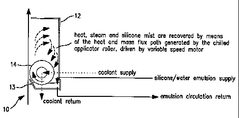
Turning first to Figure 1, there is shown a conventional
applicator for transferring a fluid of a silicone/water mixture
to a hot web 10 (the web run could be either upward (as shown),
downward or horizontal). (The
web 10 is a material web,
typically made of paper that has been printed with ink and
subsequently dried in a hot air dryer, such as an air flotation
dryer.) Heat, steam and silicon mist are generated as the web
is cooled by evaporation. The steam and silicone mist are not
directly recovered; they are typically released to ambient or
are drawn into the dryer (not shown), or a combination thereof.
This causes problems due to contamination by condensate and
mist, resulting in dripping, material build-up and corrosion,
either on surfaces near the applicator in the room, or in the
dryer itself. Of
particular concern is the ingestion of
silicone mist into the dryer where ultimately the exhaust is
treated in an afterburner. Such
silicone entrainment is a
well-known maintenance problem, as it results in build-ups and
plugging of heat recovery exchangers used in such afterburners,
rendering them incapable of processing the required exhaust
flow.
Figure 2 illustrates an embodiment of the present
invention that addresses these problems, such as by capturing
the heat, steam and silicone mist within an applicator
enclosure 12, and optionally recovering the captured material
for re-use. Thus,
a silicone/water supply is fed to a
containment vessel 13, and an applicator 14 such as a roller is
positioned so that a portion of the applicator surface is in
contact with the fluid in the vessel 13. The
applicator 14 .
optionally may be cooled such as by supplying a suitable
cooling liquid (e.g., water) to the interior of the applicator.
This cooling liquid may be recycled through an interior flow
path in the applicator and suitable piping. The applicator 14
may also include a surface treatment to enhance wettability,
such as a hydrophilic coating applied by flame spray or
sputtering processes to metallic surfaces, or to improve
resistance to adhesion of ink solids.
Suitable coatings are
9
CA 02676814 2013-04-09
well known to those skilled in the art and are commercially
available, such as from Racine Flame Spray, Inc. In a
preferred embodiment, a surface treatment of chrome, finished
to a very smooth surface, preferably less than 5.0 Ra 10-6 inches, most
preferably less than 1.0 Ra 10-6 inches, is used for sufficient wetting
and ink resistance.
As the applicator 14 contacts the silicone/water mixture,
a portion of the mixture is carried on the surface of the
applicator and is subsequently applied to the web 10 as the
applicator 14 rotates. The direction the applicator 14 rotates
is not particularly limited; it can rotate either in the
direction of web travel or counter to the direction of web
travel. One skilled in the art of web handling may prefer a
web travel direction, substantially vertical, either in an
upward direction, or downward direction in order to best
accommodate overall layout of the press line components
preceding and following said applicator. For a web traveling
in a substantially upward direction, rotation counter to web
travel generally allows more silicone/water mixture to be
applied to the web per roller revolution than rotation in the
direction of web travel. Conversely, for a web traveling in a
substantially downward direction, rotation counter to the web
travel generally applies less silicone/water mixture to the web
per roller revolution than rotation in the direction of travel.
The speed of the surface speed of the applicator roller, as
set by the speed of rotation of the applicator roller, is much
slower than the web speed. The ratio of roller surface speed
to web speed is typically in the range of 0.001 to 0.03, though
wider ranges are possible. A variable speed motor can be used
to drive the applicator 14 to obtain the desired amount of
silicone to be applied to the web. In the case of applying
silicone simultaneously to both sides of the web, it is also
preferred to have independent control of roller speed for each
applicator roller to allow operators to control application for
more or less silicone to be applied to one side of the web
versus the other.
CA 02676814 2009-07-28
WO 2008/118284
PCT/US2008/003138
The applicator 14 is preferably completely or
substantially enclosed within enclosure 12, so as to contain
the steam and water vapor generated upon evaporation from the
web. The
cooled applicator 14 thus provides a surface or
substrate for condensation of the steam and water vapor and
carries the condensate and silicone mist back to the vessel 13.
Figure 3a illustrates the applicator in a web line
arrangement following drying in a single or multi-zone dryer
15. In the embodiment shown, the web path exiting the dryer 15
is directed downward, although the invention is not to be so
limited. The atmosphere inside of the dryer 15 is separated
from the water vapor and silicone mist generated in the process
of applying a silicone/water mixture to cool the web and
provide surface treatment to the web (such as a slip agent)
firstly by a seal enclosure comprised of a smoke tunnel 16
fitted to dryer exit roller 21, and secondly by the applicator
enclosure 12. Primary chill roller 21 can be positioned at the
exit of the smoke tunnel 16 (coolant connection and tempering
control unit for the primary chill roller 21 not shown) to cool
the web. The coolant supply temperature to chill roller 21 is
typically in the range of 15 to 50 C, with 20 to 35 C being the
preferred range. In the
embodiment shown, two silicone/water
applicators 14, 14' are used, each being a roller and
communicating with a respective supply vessel 13, 13'. The
silicone/water mixture is supplied to the vessels 13, 13' via a
circulating system, including a recirculation pump 17 in fluid
communication with a sump tank 18 that receives the
silicone/water supply from a suitable source. Excess silicone
in the vessels 13, 13' can be returned to the sump tank as
shown. Applicator rollers 14, 14' receive coolant supply flow
through feed lines 25, 25'. Flow
of coolant is admitted to
rollers 14, 14' through rotary unions. Internal flow passages
are provided inside rollers 14, 14' to promote good fluid heat
transfer to the cylindrical shells of rollers 14, 14' as is
well known to those skilled in the art of chill roll design.
Coolant return lines 26, 26' conduct spent coolant back to the
main coolant return line. The coolant supply temperature to
applicator rollers 14,14' is typically in the range of 10 to
11
CA 02676814 2013-04-09
40 C, with 12 to 25 C being the preferred range. A plurality
of chill rollers can be placed downstream of the applicators to
further cool the web. A coolant supply and return, along with
a coolant tempering control unit 19, function to supply
suitable coolant to each of the rollers as is known in the art.
Figure 3b illustrates the applicator in a web line
arrangement following drying in a single or multi-zone dryer 15
similar to the embodiment of Figure 3a, except that the web
path exiting the dryer is directed upward.
Accordingly, in the foregoing embodiments, liquid from a
supply, containing water and silicone oil mixture, for example,
is applied to a web by at least one applicator. Heat from the
web evaporates at least a portion of the water and the
resulting water vapor is confined to a volume immediately
surrounding the at least one applicator by an enclosure. The
at least one applicator is cooled internally by a coolant
media, preferably water, to a temperature preferably within the
range of 10 to 40 C, with 12 to 25 C being the preferred range
to promote recovery of the evaporated water on the applicator
surface by condensation, while avoiding buildup of contaminant
material such as ink solids on the applicator surface.
Furthermore, silicone mist that is generated by the function of
the applicator, as occurs from the splitting of the liquid film
at a location where the web separates from the tangent of the
applicator roller surface, can be recovered. Mist is confined
and recovered by physical contact with condensed water by means
of wetting. Additional cooled rollers within the enclosure can
be used to provided additional surface area for condensation
and cooling energy to provide maximum recovery of water vapor
and silicone mist, as illustrated in Figure 4a.
Figure 4b shows an embodiment with additional condenser
applicators on both sides of the web and within the enclosure
or vapor chamber. Pairs of first and second rollers may be in
close contact or may be spaced apart to allow greater time for
water evaporation from the web within the span between rollers,
as is shown in Figure 4a. Silicone
fluid, for example, is
applied directly to the second applicator 14 by means of liquid
film contact with the first applicator 14a. As in the
12
CA 02676814 2009-07-28
WO 2008/118284
PCT/US2008/003138
embodiment of Figure 4a, both the first and second applicators
of each pair are cooled, such as by an internal coolant flow,
in order to provide means of recovering water vapor and
silicone mist by condensation and wetting phenomena.
Figure 4c illustrates an embodiment wherein a transfer
roller for improved cleanability is provided. A
cooled pan
applicator 14 carries fluid from the pan by means of rotation
and transfers the fluid to the transfer roller 24, but does not
directly contact the web 10. The
fluid carried by the pan
applicator 14 is cooled by contact with the applicator surface
prior to being transferred to the transfer roller 24. The
transfer roller 24 preferably has a surface treatment in order
to enhance the amount of fluid carried on its circumference.
This treatment is preferably in the form of macro pores or
pockets in the surface of the roller 24, such as that applied
to an anilox roller. The macro pores carry excess fluid for
keeping the roller surface cool while transferring only a
portion of the fluid to the web. Thus, the transfer roller 24
effectively has a cooled surface capable of promoting the
condensation function of the above-mentioned condenser roller
of Figure 4b, but without the need for a flow path of coolant
internal to the roller. This transfer roller design allows for
simple removal and cleaning of the roller without disconnection
of coolant lines and handling the weight of a fluid-filled
roller.
Figure 4d illustrates an embodiment where ventilation is
included in the enclosure 12 that does not directly connect to
the room or to the dryer enclosure, but rather includes a mist
elimination device, such as the Air King filter device
commercially available from Iowa Distributing Inc. of Cedar
Rapids. This feature offers additional flexibility in control
of moisture recovery and mist collection. At least a portion
of the water vapor and silicone mist is removed from the
enclosure 12 by withdrawing a regulated airflow from the
applicator enclosure 12 and passing that flow through the
filtering device 30. The air from the filtering device is then
free from harmful contaminants and may be used for make-up air
to the room or to the dryer make-up air intake. The airflow
13
CA 02676814 2009-07-28
WO 2008/118284
PCT/US2008/003138
can be regulated by an airflow damper 31 and vent fan 32 (or a
variable speed blower) to withdraw more or less flow, which as
described previously, contains water evaporated from the web
10, thus providing an additional means of moisture regulation
independent of the amount of silicone oil that is desired to be
applied to the web 10. For example, if it is desired to apply
a greater amount of water to the web for either cooling or for
the addition of moisture to the paper, without changing the
amount of silicone oil applied, less airflow is withdrawn from
the applicator enclosure 12, thus causing a greater amount of
water to be recovered by condensation on the cooled
applicator(s) and subsequently applied to the web. Conversely,
if less water is to be applied to the web 10, a greater amount
of airflow is withdrawn from the applicator enclosure 12,
thereby reducing the amount of water vapor available for
condensation on the cooled applicator(s) and condensing
roller(s) while the amount of silicone oils applied remains
unchanged.
As previously described, it is desirable to ventilate the
silicone applicator roller enclosure to prevent silicone mist
from escaping to the room or into the dryer. Also
as
described, it desirable to promote rapid recovery of the steam
evaporated from the silicone/water in the immediate vicinity
of the web-to-roller contact area on the cooled applicator
roller surface. Figure 8A discloses a preferred arrangement
for a substantially downward running web, which utilizes the
web motion to promote the flow of air in a desired flow path,
and also encloses a volume immediately following the roll-to-
web contact area, that distance along the web path direction
being within 200mm or less. As is known to those skilled in
the art, a boundary layer of air follows a moving surface,
such as a web, owing to the viscous properties of the fluid
and the shear forces created by the movement of said surface
relative to the bulk volume of fluid. As
such, the web
provides a motive force to impart kinetic energy to said air
causing it to flow into the top of the applicator enclosure of
Figure 8A. At the
area of web-to-roller contact, said
boundary air is prevented from advancing further in the
14
ak 02676814 2009-07-28
WO 2008/118284
PCT/US2008/003138
downward direction as the roller effectively acts as a dam to
said boundary flow. Without the upper enclosure of Figure 8A,
said flow of boundary air would dissipate into the room,
mainly above the roller, and at least a portion of said air,
potentially containing silicone mist, may return to the dryer
exit web slot with undesirable results described earlier. The
upper enclosure of Figure 8A provides a means of passively
(without use of a fan or other additional mechanical device to
force the air to move) guiding said air over the roller and
directing said air downward beyond the silicone pan to a
location below the pan, thus preventing the potential of
silicone mist from returning upward to the dryer exit opening.
This upper enclosure creates a flow passage to utilize the
kinetic energy of the moving boundary layer to passively
conduct the air around the roller and silicone pan and down
below applicator assembly, away from the dryer exit.
In and immediately below the area of web-to-roller
contact, it is desired to maximize the capture steam generated
by the evaporation of the water contained in the
silicone/water fluid that has just been transferred to the hot
web at the contact area. As
described earlier, the cooled
applicator roller provides as ready surface for the recovery
of said steam as water by means of rapid condensation. The
lower baffle of Figure 8A creates a labyrinth-type seal
between said baffle and the web, and establishes a volume
confined by the web, applicator roller, pan, fluid in the pan,
lower enclosure and said baffle. Thus steam generated from
the hot web is enclosed and allowed to condense on the cool
surface of the pan and said baffle. A
secondary pan is
positioned under the silicone reservoir pan and said baffle to
catch said condensed steam and return it as water to the
silicone supply source.
Figure 8b shows an embodiment preferred for an upward
running web. As
before, the moving web carries a boundary
layer of air, in this case said web travels upward toward the
area of web-to-roller =contact. Again,
the roller acts as a
dam preventing passage of said boundary air past said web-to-
roller contact area. To
prevent said air from dissipating
= 15
CA 02676814 2009-07-28
WO 2008/118284
PCT/US2008/003138
back toward the exit of the dryer, an outer enclosure creates
a flow passage to utilize the kinetic energy of the moving
boundary layer to passively conduct the air under and around
the silicone pan and above applicator assembly, away from the
dryer exit. An upper enclosure provides a labyrinth-type seal
between said enclosure and the web, and creates a confined
volume bounded by the web, applicator roller, pan, fluid in
the pan, and said upper enclosure. Thus steam generated from
the hot web is enclosed and allowed to condense on the cool
surface of the roller, thus recovering the said steam and
returning it to the silicone supply source.
16