Note : Les descriptions sont présentées dans la langue officielle dans laquelle elles ont été soumises.
CA 02679323 2009-08-26
WO 2008/117250 PCT/1B2008/051127
1
DISCHARGE DEVICE FOR VISCOUS LIQUIDS
FIELD OF THE INVENTION
This invention relates to improvements in discharge devices, such as diaphragm
taps, designed
for delivering viscous liquids such as concentrated laundry detergents.
BACKGROUND OF THE INVENTION
The eventual replacement of today's so-called "1X" liquid laundry detergents
and liquid fabric
softeners with modern, more concentrated "2X" formulations is of considerable
commercial
importance. Doubling the concentration of active ingredients in such
compositions allows usage
levels to be halved. Thus, for the same number of product usages, only half
the volume of
product need be supplied to the consumer. This results in considerable savings
in packaging
materials and shipping costs, as well as simplifying transportation and
storage of the product by
the consumer. Importantly, the overall carbon footprint of the product is
reduced.
Of course, the change-over from (1X) formulations to (2X) formulations is not
without its
problems. Changing the habits and practices of consumers can be remarkably
challenging,
especially since most consumers are quite satisfied with their current (1X)
products.
Accordingly, consumers must be educated regarding the benefits of the (2X)
formulations and are
quick to notice and assert their displeasure concerning any perceived problems
associated with
the change-over. On the other hand, consumers do expect some differences in
product attributes
that signal they are using the new (2X) version,
One expected visual and tactile signal for any concentrated liquid formulation
is that it be more
viscous that its less concentrated version. This expectation is easily met
with liquid laundry
detergents, due at least in part to the phase properties of the detersive
surfactants used therein.
For example, conventional (1X) liquid laundry detergents typically have
viscosities in the range
of 250 to 300 cps, whereas the counterpart (2X) formulations may have
viscosities in the range of
about 350 to about 700 cps, typically about 350 to about 500 cps.
CA 02679323 2009-08-26
WO 2008/117250 PCT/1B2008/051127
2
One quite successful innovation in the marketing of (1X) formulations has been
the introduction
of large, economy-size containers from which liquid product is dispensed by
means of a tap,
rather than by pouring. Of course, the introduction of the (2X) formulation
does allow the size of
the container to be reduced, but tap dispensing is still desirable on the
larger product sizes.
Unfortunately, however, it has now been unexpectedly discovered that the
higher viscosities of
(2X) formulations can result in unacceptably slow product flow through the tap
dispensers that
are commercially available for (1X) formulations. Moreover, to change the
overall design and
size of the currently-available taps would require quite expensive re-tooling.
This presents a
problem to the manufacturer: to meet consumer expectations for a (2X) product
that is more
viscous, but has an acceptable flow rate through a dispenser tap that can be
produced
economically. The present invention addresses this flow problem in a cost-
effective manner, as
will be seen from the following disclosure.
BACKGROUND ART
US Patent 4,452,425, to Anthony J. Lucking, issued June 5, 1984, describes a
plastic diaphragm
tap comprising a tubular body open at one end and closed at the other end by a
flexible resilient
diaphragm. The diaphragm is connected to a shaft comprising a valve element,
said valve
element being arranged to close a valve seat at the open end of the tap.
Finger pressure on the
diaphragm displaces the valve element and opens the tap. Conversely, release
of said pressure
allows the normal resilience of the diaphragm to re-seat the valve element
against the valve seat,
thereby closing the tap.
The Lucking tap is disclosed for delivering liquids, such as wine or milk,
from a storage
container. The configurations of the valve seat and valve element in this tap
are taught to
cooperate so that the valve element self-centers against the valve seat to
close the tap in dripless
fashion. Reference can be made to US 4,452,425 for details of the manufacture
and use of said
Diaphragm Tap.
CA 02679323 2009-08-26
WO 2008/117250 PCT/1B2008/051127
3
Despite the teachings of US 4,452,425, it has been the experience of the
Applicants herein that
diaphragm taps cannot be completely relied on to self-center and to
satisfactorily close in dripless
fashion under all circumstances. As will be appreciated, drippage of liquid
laundry products from
the tap would be unacceptable to the user of such products. It has also been
discovered that,
during use, the valve can skew off-center, with the result that liquid product
can sometimes exit
predominantly towards the rear of the tap, whereas at other times it can exit
towards the front.
This can lead to product spillage and a poor consumer experience.
In order to ensure proper centering of the valve, which is essential to ensure
dripless closure and
smooth, repeatable product flow from dose-to-dose, diaphragm taps can be
fitted with a valve
guide. The valve guide centrally positions the shaft that communicates between
the diaphragm
and the valve element in the tubular body. The valve guide is typically
affixed to the internal
walls of the tubular body by means of substantially horizontal support ribs,
said ribs fixedly
positioning the valve guide substantially concentrically with the midline axis
of the tubular body.
The valve guide comprises a throughhole through which the shaft slidingly
passes as the valve is
opened and closed by the respective application and release of pressure on the
diaphragm.
Commercial experience with the delivery of conventional (1X) liquid laundry
detergents using
diaphragm taps that comprise valve guides has been excellent. As noted above,
however, it has
now been discovered that the flow rate of concentrated (2X) liquid detergents
through such taps
is too slow for some consumers. This is because the diaphragm tap is gravity-
fed. Accordingly,
as the product container empties with successive uses and the hydrostatic
pressure decreases
correspondingly, the flow rate is reduced.
Having discovered the flow rate problem with diaphragm taps used to deliver
viscous liquids, it
has now also been discovered that a more consumer acceptable flow rate for
(2X) products can be
achieved by modifying the tap in the manner disclosed herein. Surprisingly,
the tap modified
according to at least a preferred embodiment of the invention also provides
consumer-acceptable
flow rates across a range of viscosities, and even for conventional (IX)
liquid products. This is a
considerable commercial advantage, since the manufacturer of such products,
e.g., liquid fabric
CA 02679323 2009-08-26
WO 2008/117250 PCT/1B2008/051127
4
enhancers such as detergents and softeners, can use the same tap
interchangeably with both (1X)
and (2X) liquid products.
SUMMARY OF THE INVENTION
In one aspect, the present invention comprises a discharge device comprising a
body 100 having a
hollow interior 200, said body comprising a liquid inlet portion; a liquid
outlet portion
comprising a first end and a second end, wherein said first end comprises a
button, wherein said
liquid outlet has an orifice comprising an orifice surface area comprising a
stem and valve system
comprising a rib and a valve guide comprising a valve system surface area
wherein said stem
passes through said valve guide, and wherein,
said valve system surface area and said orifice surface area have a ratio of
less than about 35%,
preferably less than about 30%, or 20% or even 10%.
In one embodiment, the present invention encompasses a discharge device (i.e.,
"tap") having a
liquid outlet with a hollow interior. The valve system is located at the
junction of the liquid inlet
and the liquid outlet. The valve guide system has a valve guide and a first
rib. The valve guide
system has a valve guide having a valve guide width. The valve guide width is
preferably less
than about 1.15 mm. The first rib has a first rib width having a first rib
width which is preferably
less than about 2.5 mm.
In another embodiment, the invention encompasses a discharge device comprising
a body having
a hollow interior; a liquid inlet comprising a liquid inlet surface area, a
liquid outlet wherein said
liquid outlet has a hollow interior comprising a stem and a valve guide
comprising a top, a
bottom, and a valve guide surface area, said stem passes through said valve
guide, and
characterized in that said bottom of said valve guide is above (preferably, at
least about 3 mm)
said liquid inlet.
The invention also encompasses an article of manufacture, comprising a
container comprising a
reservoir for storing a liquid composition, especially a liquid ("2X")
detergent having a viscosity
above about 350 cps, and an improved diaphragm tap, as disclosed above and as
described more
fully hereinafter.
CA 02679323 2013-01-03
4a
In one particular embodiment there is provided a discharge device comprising a
body
having a hollow interior, said body comprising a liquid inlet portion, a
liquid outlet
portion comprising a first end and a second end, wherein said first end
comprises a
button that is a domed diaphragm, wherein said liquid outlet portion has an
orifice at
said second end, wherein a valve system is located inside said hollow interior
of said
liquid outlet, wherein said valve guide system comprises: i. a stem having one
end
fixedly inserted into a downwardly accepting socket of said button and another
end
terminating in a frusto-conical valve element seated in sidewalls of the
second end of
said liquid outlet portion, wherein said stem passes through a valve guide;
wherein
said valve guide has a valve guide width through which said stem passes,
wherein said
valve guide is in a liquid flow path of said second end, wherein said valve
guide width
is at least 1.15 mm wide; and ii. a first rib connecting said valve guide to
said sidewall
of said second end.
CA 02679323 2009-08-26
WO 2008/117250 PCT/1B2008/051127
BRIEF DESCRIPTION OF THE DRAWINGS
Fig. 1 is a perspective view of an embodiment of the discharge device of the
present
invention;
Fig. 2A is a cross-section view along line 2A-2A of the discharge device of
FIG. 1.
Fig. 2B is a cross-section view along line 2B-2B of the discharge device of
FIG. 1 while
the button is pressed.
Fig. 2C is a cross-section view along line 2A-2A of an alternative embodiment
of the
discharge device.
Fig. 3 is a front view of the discharge device.
Fig. 4 is a cross-section view along line 4-4 of the discharge device of FIG.
3.
Fig. 5 is a front view of an alternative embodiment of the discharge device.
Fig. 6 is a cross-section view along line 6-6 of the alternative embodiment of
the
discharge device of FIG. 5.
Fig. 7 is a front view of an alternative embodiment of the discharge device.
Fig. 8 is a cross-section view along line 8-8 of the alternative embodiment of
the
discharge device of FIG. 7.
Fig. 9 is a front view of an alternative embodiment of the discharge device.
Fig. 10A is a cross-section view along line 10A-10A of the alternative
embodiment of the
discharge device of FIG. 9.
Fig. 10B is a front view of an alternative embodiment of the discharge device.
Fig. 10C is the cross-section view along line 10C-10C of the discharge device
of 10B.
Fig. 11 is a front view of an alternative embodiment of the discharge device.
Fig. 12 is a perspective view of an alternative embodiment of the discharge
device.
Fig. 13 is a graph showing fluid flow through dispenser taps.
The figures herein are not necessarily drawn to scale.
DETAILED DESCRIPTION OF THE INVENTION
Section A will provide terms which will assist the reader in best
understanding the features of the
invention, but is not intended to introduce limitations in the terms
inconsistent with the context
in which they are used in this specification. These definitions are not
intended to be limiting.
CA 02679323 2009-08-26
WO 2008/117250 PCT/1B2008/051127
6
Section B will discuss the discharge device of the present invention. Section
C will discuss
examples of the present invention.
A. TERMS
As used herein, the "orifice" is measured as the cross-section of the smallest
perimeter of the
liquid outlet. Of course, for a cylindrical outlet, the perimeter has a
constant value.
The viscosity of the liquid compositions can be measured at 21.1 C using a
Brookfield LV DV II
instrument conducted according to the manufacturer's instructions with the #31
spindle run at 60
rpm. This approximates the shear rate, ca. 20 1/sec, of the product being
dispensed from the
container.
All percentages herein are by weight, unless otherwise specified.
The dimensions and values disclosed herein are not to be understood as being
strictly limited to
the exact numerical values recited. Instead, unless otherwise specified, each
such dimension is
intended to mean both the recited value and a functionally equivalent range
surrounding that
value. For example, a dimension disclosed as "40 mm" is intended to mean
"about 40 mm".
B. PACKAGE OF THE PRESENT INVENTION
I. Discharge Device
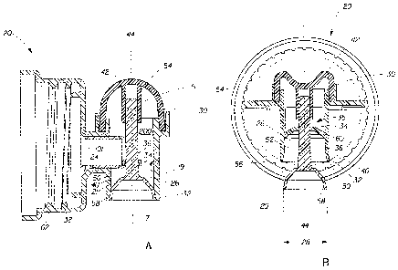
Referring to FIG. 1, a discharge device 20 is shown which is designed to
dispense a liquid
composition 1 from container 22. In this embodiment the container comprises
filler opening 2 that
can be repeatedly sealed and opened, e.g., with a screw cap 3. In-use, the
screw cap is loosened
or removed to allow air to enter the container. Indicia, such as arrow 4 or
other instructions can be
provided on the container as a reminder to the user to loosen the cap during
use.
Referring to FIG. 2A, FIG. 2B and FIG. 2C, the present invention provides a
discharge device 20
for dispensing liquids, especially viscous liquids from a container 22(See
FIG. 1). In the
embodiment shown, the body 100 of the discharge device 20 has a liquid inlet
portion 24 and a
CA 02679323 2009-08-26
WO 2008/117250 PCT/1B2008/051127
7
tubular liquid outlet portion 26. The tubular liquid outlet portion 26 has an
orifice 29, a first
(proximal) end 30, and a second (distal) end 32 opposite to the first end 30.
The orifice 29 of the
tubular liquid outlet portion 26 opens and closes by a valve system 35 (see
FIGS. 2A ¨ 10B)
comprising a stem 36 which passes through the throughhole 6 (see FIG. 3) in
valve guide 34. (see
FIG. 3) In this embodiment, the stem 36 is fixedly inserted into the
downwardly accepting socket
of button 42, which, in this embodiment is a domed diaphragm, as discussed
more fully
hereinafter.
Generally, referring again to FIG. 2A and FIG. 2C, when the button (diaphragm)
42 is unpressed,
the stem 36, terminating in a frusto-conical valve element 21, which can be
seated in the
sidewalls 40 of the tubular liquid outlet portion 26 by compressing against
the sidewall 40 so that
no liquid can flow from the container 22 (See FIG. 1) with which the discharge
device 20 is used.
Referring to FIG. 2B, when pressure is applied to the button 42, the stem 36
moves downwardly
along the midline axis 44 to unseat the valve element 21 from the outlet
orifice 29 which may
have conical seating 50 constituted by the walls 40. As a result, liquid flows
along a liquid flow
passageway around the stem 36 and valve guide 34 and rib(s) 60 and through the
valve system 35
(see FIGS. 3 ¨ 10B). In a preferred embodiment shown in Fig. 2A, the sidewall
40 has a terminal
edge 7, which is preferably beveled in order to sealingly seat the frusto-
conical valve element 21
when the valve is in the closed position.
Referring to FIG. 1, using a discharge device 20 of this type avoids the
problems caused by a
number of soap containers, bleach containers, conditioner containers, and
other containers around
the laundry area. It also eliminates the need for lifting a gallon container
or other heavy item for
handling this matter by being able to discharge the liquid from any surface.
Moreover, it also
reduces the amount of time needed to discharge the liquid and simplifies the
application of the
right amount of the product at the right time, thereby reducing waste. For
those without the
strength to lift a heavy container, this discharge device 20 and container 22
keep the washing
liquid readily available.
The discharge device 20 and container 22 may be formed from any suitable
material such as high-
density polyethylene, low-density polyethylene, polypropylene or linear low-
density polyethylene.
CA 02679323 2009-08-26
WO 2008/117250 PCT/1B2008/051127
8
A. Liquid Inlet
Referring to FIG. 2A, generally, the liquid inlet 24 is provided to allow
liquid to flow therethough
from the container 22 (see FIG. 1) and into and through liquid outlet portion
26 and out of orifice
29.
The attachment 62 can be formed with screw threads 38 (See FIG. 2A) to allow
joining of the
discharge device 20 to a container 22 (see FIG. 1) at the container's liquid
egress port 101 (FIG.
2A). It will be appreciated that the discharge device 20 can be attached to a
container 22 in other
ways, but a connection which is not destroyed on removal of the discharge
device 20 after
emptying the container 22 may be preferred because it makes the discharge
device 20 reusable.
Other ways attachment 62 can be used to attach the discharge device 20 and the
container 22 are
by pressure seal, an adhesive seal, a locking closure, a screw-type closure, a
snap-fit closure, a
heat seal, an ultrasonic seal, and/or a plug-seal and may optionally be air-
tight and/or water-tight
as desired for example, to prevent oxidation of the pourable product,
absorption of moisture from
the air, and/or water damage to the pourable product.
B. Liquid Outlet
Referring to Fig. 2B, the liquid outlet portion 26 of the device 20 is formed
to allow liquid to
flow therethrough from the container 22 and to provide a seal at the second
end 32 of the liquid
outlet 26 to prevent liquid from leaking. As stated above, the liquid outlet
26 comprises an
orifice 29, which is characterized by its cross-sectional area 28, a first end
30, and a second end
32 opposite to the first end 30. The liquid outlet portion 26 contains a valve
guide 34 and a stem
36 which passes through the valve guide 34.
i. Valve System
Referring to FIG. 3 ¨ FIG. 10B, the valve system 35 comprises the valve guide
34 and the rib(s)
60. Both are described separately in detail below. The valve system 35 can be
located anywhere
along the liquid outlet portion 26. As seen in FIG. 2A and FIG. 2B, the valve
system 35 can be in
the path of the liquid flow passageway. In other words, the liquid is in
contact with the valve
system 35 when the button 42 is depressed to release the liquid from the
container 22.
CA 02679323 2009-08-26
WO 2008/117250 PCT/1B2008/051127
9
Alternatively, as seen in FIG. 2C, the valve guide 34 of valve system 35 can
be constructed to not
be in the path of the liquid flow passageway while the liquid is flowing from
the liquid inlet 24
through the liquid outlet portion 26. In this embodiment, the bottom 9 of the
valve guide 34 is
positioned at or above the junction 8 of the liquid inlet 24 and the outlet
portion 26. In other
words, the liquid is not in substantial contact with the valve guide when the
button is depressed to
release the liquid from the container 22. In this embodiment, the valve system
35 is used as a
guide for the stem 36 to provide stability, but allows for faster liquid flow
because there is not
substantial liquid contact with the ribs and valve guide. However, it is to be
understood that this
is not a preferred arrangement for use herein, since downward pressure during
operation of the
device can cause the button to undesirably impinge on the valve guide/rib
assembly.
a. Valve Guide
Referring to FIG. 2A - FIG.10C, valve guide 34 is secured to the interior
surface 19 of sidewall
40 of the liquid outlet 26 by ribs 60. The valve guide 34 stabilizes the
liquid flow profile and
provides a maximum flow rate. Referring to FIG. 3 - FIG. 10C, the higher flow
rate is achieved
by decreasing the surface area of the elements of the valve system that limit
flow passage, which
is the valve system 35. To increase the flow through the valve system 35, the
cross sectional area
of the valve system 35 is reduced while still maintaining the valve system
35's structural
performance. Generally, reducing the cross sectional area also decreases the
width 59 of the
valve guide 34 and the width 64 of the ribs 60. Accordingly, reducing the
width which is
perpendicular to the flow of the liquid of the valve system 35 decreases drag
on fluid passing
through the liquid outlet 26. Stated otherwise, the surface areas of the top
side 13 (side facing the
proximal end of the device) of the ribs and top side 11 of the valve guide are
minimized,
compared with current commercial practice, as discussed more fully
hereinafter.
In addition, the valve guide 34 geometry can be changed to increase flow.
Referring to FIG. 10B,
the width 59 of the valve guide 34 is ovalized 61. The width 59 of the valve
guide 34 is
preferably at least less than about 1.15 mm.
b. Ribs
Referring to FIGS. 3- 10C, the ribs 60 connect the valve guide 34 to the
interior surface 19 of the
sidewall 40 of the liquid outlet 26. The ribs 60 can be part of the sidewall
(i.e., "walls") 40 by
molding or may be inserted by being bonded or spin welded. The ribs
communicate between the
CA 02679323 2009-08-26
WO 2008/117250 PCT/1B2008/051127
interior surface 19 of the sidewall and the valve guide 34. The width 64 of
the ribs 60 is
preferably at least less than about 2.5 mms. In this invention, the ribs 60
are reduced in width to
decrease drag on fluid passing through (see FIG. 3, 5, 7, 9, 10B) the liquid
outlet 26.
Referring to FIG. 4, FIG. 6, FIG. 8, and FIG. 10, in addition, the rib 60
geometry can be changed
to increase flow and reduce surface contact of the liquid with the valve
system 35. Referring to
FIG. 4 and FIG. 8, the rib 60 may be angled upward where the valve guide 34 is
in a plane above
the rib 60. Referring to FIG. 10A, in another embodiment, the rib 60 may be
angled downward
or inverted where the valve guide 34 is in a plane below the rib 60.
ii. Stem
Referring to FIG. 2A and FIG. 2B, the stem 36 forms a connection between the
button 42 and the
valve element 21 at liquid outlet 26. The stem 36 comprises a first end 54 and
a second end 56
opposite to the first end 54. The first end 54 is adjacent to the button 42
and protrudes
downwardly from the button 42. The stem 36 can have its first end 54 shown
seated in the button
42 and the second end 56 on conical (beveled) seating 50.
The second end 56 of the stem 36 comprises the valve element 21 that seals the
outlet 52 of the
liquid outlet portion 26 at orifice 29 and is the sealing for controlling the
normal or repetitive
opening and re-sealing of the discharge device 20. The second end 56 of the
stem 36 comprises
valve element 21 which can be conical or frusto-conical, and can be arranged
to seat on the edge
of orifice 29, said orifice comprising a correspondingly tapered 50 edge 7 so
as to close the liquid
outlet portion 26. The outer edge of the external surface of the valve element
is flush with the
adjacent part of the second (distal) end 32 of the liquid outlet 26 when the
discharge device 20 is
closed so that there is virtually no space within which liquid pass by virtue
of its surface tension.
A sealing bead 58 can optionally surround the stem 36 and/or valve element 21
to ensure
adequate contact pressure on the liquid outlet 26 at the terminal edge 7 of
orifice 28. The stem 36
passes through a valve guide 34. Typically, the stem 36 (including its valve
element) extends the
length of the liquid outlet portion 26. The length of the stem 36 can be any
length which fits
within the liquid outlet portion. In one alternative embodiment, the length of
the stem 36
(including valve element 21) can be about 33 mms.
CA 02679323 2009-08-26
WO 2008/117250 PCT/1B2008/051127
11
iii. Button
Referring to FIG. 2A and FIG. 2B, when the button 42 is depressed, liquid is
released from the
liquid outlet portion 26 through outlet 52. Specifically, when the button 42
is depressed, the
button 42 acts on the stem 36 movable along axis 44 so that orifice 29 of
outlet portion 26 is
opened. The stem 36 is supported by the valve guide 34 and rib(s) 60. When the
valve is
opened, liquid is allowed to flow from the container 22 (see FIG. 1) through
the liquid inlet 24
past the stem 36 and valve guide 34 and ribs 60 and out of the orifice 29 of
the liquid outlet
portion 26. On release of the button 42, the stem retracts and outlet portion
26 is closed.
The button 42 can have a chamfered socket portion. The stem 36 can have its
first end 54 shown
seated in the button 42 and the second end 56 including the valve element 21,
on conical seating
50. The valve element 21 at the second end 56 of the stem 36 seals the outlet
of the discharge
device 20 and is the sealing for controlling the normal or repetitive opening
of the discharge
device 20.
In the preferred "diaphragm tap" embodiment shown in the FIGS., the button
(i.e., the
diaphragm) 42 needs to be resilient, but flexible, so that it is capable of
large deformation under
manual pressure but subsequently resuming its original shape when the pressure
is removed. The
button 42 is suitably formed from an elastomeric polymer, for example ethylene
vinyl acetate,
metallocene polythene or polybutylene terephthlate.
iv. Calculation of the Ratio of the Area of the Orifice Compared to the
Valve
System
The ratio of the area 28 of the orifice 29 (which, in a preferred embodiment,
corresponds to the
cross-sectional area, i.e., the "bore", of the tubular outlet portion 26)
compared to the area of the
valve system is calculated by measuring the cross-sectional area,
perpendicular to the flow of the
liquid, of the valve system 35, i.e., especially the surface area 10 of the
top side 11 of the valve
guide and the surface area 12 of the top side 13 of the valve guide support
ribs and dividing this
area by the area 28 of the orifice 29.
To illustrate, the area of the valve system may be calculated as 53.9 square
millimeter and the
area of the orifice may be calculated as 152.2 square millimeter. Thus, 53.9
divided by 152.2 is
CA 02679323 2009-08-26
WO 2008/117250 PCT/1B2008/051127
12
the ratio 35.39%. Thus, the discharge device 20 can have ratio of the area 29
of the orifice 28 to
the area of the valve system 35 obstructed at less than "about" 35% in the
direction of the liquid
flow. The software used to determine the area is Sold works 2007.TM
II. Container
Referring to FIG. 1, a discharge device 20 having a container 22 of sufficient
size to rest on a
shelf and sufficient length so that a dispensing mechanism is held
conveniently for use provides
the necessary solutions to the problems described above. The container 22 can
rest on a shelf
above the washer. The container 22 can be of sufficient size to hold a
suitable amount of powder
or liquid for washing purposes.
Preferably, the container 22 has a flat base 23 so that the container 22 can
rest easily on a shelf
mounted adjacent to the clothes washer. The container 22, at least partially,
overhangs a surface
(e.g., shelf, washer, dryer). At the overhanging portion of the container 22,
there is a discharge
device 20. Because the container 22 can be taken down from the shelf, and
placed on the washer
or other surface to be filled, and the filling aperture in the top of the unit
is large, it is easy to
refill.
The discharge device 20 can fit a cup 63 marked for measuring the amount of
liquid, which can
be removably held therein. When it is desired to do laundry, it is possible to
remove the cup 63
from the discharge device 20, place the cup beneath the discharge device 20,
press the button 42
to open the outlet 52 of the liquid outlet 26, fill the cup 63 with the
desired amount of liquid,
close the outlet 52 (FIG. 2B) of the liquid outlet 26 by removing any force
placed on the button
42 (FIG. 2B), and remove the cup 63 (FIG. 1) from beneath the discharge device
20. Then the
contents of the cup 63 (FIG. 1) can be added to the clothes washer in order to
do the laundry. The
cup 63 (FIG. 1) may be marked in Braille or levels for the amount of material
necessary for each
load or size of load of laundry. The cup 63 can also be marked to make it
simpler for a person
lacking laundry skills to determine how much of each laundry material is to be
used. In this
fashion, the laundry process may be more simply accomplished.
CA 02679323 2009-08-26
WO 2008/117250 PCT/1B2008/051127
13
Referring to FIG. 1, as stated above, the container 22 is attached to the
discharge device 20. The
container material can be any material. It is possible to make the container
22 of a clear plastic so
that it can be easily determined when the liquid contained therein is running
low, and when the
container 22 needs to be refilled. The container 22 may be made of transparent
material,
translucent material, opaque material or any reasonable combination thereof.
The only
requirement is that the material be inert to the laundry agent contained
therein. Clear bottle
materials with which this invention may be used include, but are not limited
to: polypropylene
(PP), polyethylene (PE), polycarbonate (PC), polyamides (PA) and/or
polyethylene terephthalate
(PETE), polyvinylchloride (PVC); and polystyrene (PS).
The transparent container 22 according to the invention preferably has a
transmittance of more
than 25%, more preferably more than 30%, more preferably more than 40%, more
preferably
more than 50% in the visible part of the spectrum (approx. 410-800 nm).
Alternatively,
absorbency of the container 22 may be measured as less than 0.6 or by having
transmittance
greater than 25% wherein % transmittance equals: 110Absorbancyx100%. For
purposes of the
invention, as long as one wavelength in the visible light range has greater
than 25%
transmittance, it is considered to be transparent/translucent. Enzyme
deactivation as a result of
UV-damage may occur at very low transmission of UV-B radiation through the
container wall.
III. Liquid
A variety of laundry agents may be used, kept handy for use and dispensed
easily.
However, it is to be understood that the formulation per se of liquid laundry
detergents and liquid
fabric enhancing agents such as fabric softeners forms no part of this
invention. Liquid
detergents typically comprise one or more anionic and nonionic surfactants,
various chelators and
builder materials, enzymes, bleaches, corrosion inhibitors, perfumes and an
aqueous carrier.
Liquid fabric softeners typically an aqueous carrier and one or more cationic
and/or silicone
ingredients that soften, lubricate and provide an anti-static finish on
fabrics. The extensive patent
literature in this field can be referred to for examples of such compositions.
For convenience, the
following is a non-limiting example of a concentrated (2X) liquid laundry
detergent for use in the
manner of the present invention.
CA 02679323 2009-08-26
WO 2008/117250 PCT/1B2008/051127
14
LIQUID LAUNDRY DETERGENT
INGREDIENT % BY WEIGHT
C12-15 alkyl ethoxylate 4.8 avg EO (commercial paste) 11.00
C12 alkyl benzene sulfonate 3.00
Sodium C12 alkyl sulfate (commercial paste) 2.50
C12-14 alkyl ethoxylate .9 EO 0.60
Citric acid 4.00
Ethanol 1.5
PEG 4000 0.08
1,2 propanediol 3.0
Monoethanolamine 2.4
Sodium hydroxide 1.8
Sodium cumene sulfonate 0.6
Suds suppressor (DC 1520) 0.01
Enzymes* 0.10
Borax 2.8
Perfume and minors 0.1
Water balance
*mixture of protease, amylase and cellulase
C. EXAMPLES
Examples of some embodiments of the invention are set forth hereinafter by way
of
illustration and are not intended to be in any way limiting of the invention.
The examples are not
to be construed as limitations of the present invention since many variations
thereof are possible
without departing from its spirit and scope. In Examples 1-VI the cross-
sectional area of the bore
of the outlet portion is about 152 mm. In all Examples the valve guide is
concentric with midline
axis 44.
EXAMPLE I
A liquid outlet comprises a hollow interior wherein a valve system is located
at the junction of
the liquid inlet with the outlet portion. The valve system comprises a valve
guide and 2 ribs. The
valve guide width is 0.75 mms. Each rib width is 1.55 mms wide.
CA 02679323 2009-08-26
WO 2008/117250 PCT/1B2008/051127
EXAMPLE II
A liquid outlet comprises a hollow interior wherein a valve system is located
at the junction of
the liquid inlet with the outlet portion. The valve system comprises a valve
guide and 3 ribs. The
valve guide width is 0.75 mms. Each rib width is 1.55 mms wide.
EXAMPLE III
A liquid outlet comprises a hollow interior wherein a valve system is located
at the junction of
the liquid inlet with the outlet portion. The valve system comprises a valve
guide and 1 rib. The
valve guide width is 0.75 mms. The rib width is 1.55 mms.
EXAMPLE IV
A liquid outlet comprises a hollow interior wherein the bottom of the valve
guide of the valve
system is located from about 1 mm to about 5 mm above the junction of the
liquid inlet with the
outlet portion. The valve system comprises a valve guide and 2 ribs. The valve
guide is 1.0 mm
wide. Each rib tapers and has two widths; the first width is 1.0 mm wide and
the second width is
1.2 mm.
EXAMPLE V
A discharge device comprises an orifice surface area and a valve system
surface area. The orifice
surface area is 152.2 square millimeter. The combination of the ribs and the
valve guide
comprise a valve system surface area. The valve system comprises 2 ribs and a
valve guide.
Because the valve system surface area is 29.7 square millimeter and the
orifice surface area is
152.2 square millimeter, the ratio of the valve system area and the orifice
surface area is 19.5%.
The stem is 33 mms in length.
EXAMPLE VI
A discharge device comprises an orifice surface area and a valve system
surface area. The orifice
surface area is 152.2 square millimeter. The combination of the ribs and the
valve guide
comprise a valve system surface area. The valve system comprises 2 ribs and a
valve guide.
Because the valve system surface area is 32.8 square millimeter and the
orifice surface area is
152.2 square millimeter, the ratio of the valve system area and the orifice
surface area is 21.6%.
The stem is 33 mms in length.
As can be seen from the foregoing, the discharge devices herein may be of
various types, but are
all characterized by a stem that carries a valve element. The stem/valve
element combination
CA 02679323 2009-08-26
WO 2008/117250 PCT/1B2008/051127
16
rides in the bore of the tubular outlet portion of the device, through which
the liquid composition
flows to exit the device. The valve guide herein functions to substantially
center the shaft in the
bore, thereby assuring that the valve element will be properly seated when the
valve is closed.
As noted above, the discharge device operates by gravity. The outlet portion
of the device
comprises a proximal end, i.e., the end where downward pressure is applied by
the user to open
the valve, and a distal end, i.e., the end from where the liquid composition
is discharged when the
valve is opened. It will be appreciated that the proximal end can comprise all
manner of elements
to which downward hand or finger pressure can be applied in order to open the
valve. Various
tabs, knobs, pads and the like can be envisioned. In general, such elements
may be referred to
generically as "buttons." In one embodiment, such buttons can be spring-loaded
so that the valve
is automatically re-seated when the downward pressure is released.
Furthermore, it will be appreciated that the valve stem can be associated with
the activator
"button" by any convenient means, including, but not limited to, adhesive
bonding, screw
threads, sweat fitting, and the like.
Likewise, various valve elements for sealing the open distal end of the outlet
portion can be
envisioned. For example, a simple 0-ring closure element would serve the
sealing function, as
would a washer assembly, and the like.
FIG. 13 illustrates the flow problem associated with (2X) liquid detergents
using current,
commercial discharge devices and the solution afforded by the present
invention.
FIG. 13 is a graphical representation of the flow of a liquid detergent from a
container through
the tubular outlet portion (bore) of domed taps. The variation in flow as the
container
progressively empties is clearly seen for both (1X) and (2X) compositions. In
FIG. 13, the valve
guide comprising an annular ring is held in place by support ribs in the flow
path of the liquid
detergent flowing through the bore and exiting the tubular outlet portion of
the tap. In FIG. 13,
curve 14 illustrates the flow of a (1X) liquid detergent having a viscosity of
about 190 cps using a
container comprising a preferred domed tap according to the present invention
having a so-called
CA 02679323 2009-08-26
WO 2008/117250 PCT/1B2008/051127
17
"thin" valve guide with two support ribs and an annular ring, as described
hereinafter. Curve 15
illustrates the flow of a (1X) liquid detergent with a current commercial
valve guide having four
support ribs and an annular ring, whose total top surface area is about twice
that of the aforesaid
"thin" device herein. Curve 16 illustrates the flow of a (2X) liquid detergent
having a viscosity
of about 465 cps using the "thin" device of a preferred embodiment of the
present invention.
Curve 17 shows the flow of the (2X) detergent with the aforesaid current
commercial four-rib
device.
As can be seen, an improvement in flow of about 30% is achieve by the present
device as
compared with the current commercial device when considering the latter stages
of delivery of a
(2X) liquid detergent.
Having thus described various aspects of the present invention, the following
describes and
exemplifies preferred, but non-limiting embodiments of the preferred devices
herein, comprising
diaphgragm taps, and their use, but is not intended to limit the scope of the
invention.
In one aspect, the invention encompasses, an article of manufacture,
comprising:
a) a container comprising a liquid composition releasably housed within said
container;
b) a diaphragm tap associated with said container for dispensing said liquid
composition,
said tap comprising:
i) a tubular outlet portion having a cross-sectional area (e.g., about 120-
200
mm2; preferably about 150 mm2) , said tubular outlet portion comprising
an open proximal end and an open distal end, said distal end comprising a
terminal edge, said tubular outlet portion comprising a sidewall having an
inner surface;
ii) an inlet portion integrally formed with the sidewall of said tubular
outlet
portion at a junction (and, in a non-limiting example, intersecting at about
a 90 angle), said inlet portion being associated with said container and
providing fluid communication for said composition between said
container and said tubular outlet portion;
CA 02679323 2009-08-26
WO 2008/117250 PCT/1B2008/051127
18
iii) a valve assembly comprising a flexible resilient domed diaphragm
fitted
around the open proximal end of said tubular outlet portion and extending
upwardly therefrom and comprising a downwardly accepting socket for
receiving the first end of a stem, said stem carrying a valve element at its
second end, said valve element being frusto-conical and configured to seat
at the distal end, preferably on said terminal edge of the distal end, of said
outlet portion, said terminal edge preferably being beveled to sealingly
match said frusto-conical valve element; and
iv) a valve guide, preferably comprising an annular fitment (preferably,
ring),
said valve guide having a throughhole through which said stem slidingly
passes, said valve guide being substantially centrally affixed with respect
to the sidewall in said tubular outlet portion by means of support ribs
communicating between said valve guide and the inner surface of the
sidewall of said tubular outlet portion. In one aspect of the invention, said
tap is characterized by: said valve guide and support ribs, together, having
a total top surface area that is less than about 35%, preferably less than
about 30%, most preferably less than about 20%, or even 10%, of the
cross-sectional area of said tubular outlet portion of said tap. In a highly
preferred mode, two support ribs are used to affix the valve guide, which is
most preferably an annular ring. (Shown as 24 in FIG. 9)
In another aspect of the invention, said diaphragm tap employed on said
article comprises a valve
guide, preferably an annular ring, having a top surface area less than about
20.4 mm2, preferably
from about 5 mm2 to about 15 mm2, and two support ribs, said two support ribs,
together, having
a top surface area less than about 21 mm2; and in a highly preferred mode,
said tubular outlet
portion has a cross-sectional area (i.e., bore) from about 145 mm2 to about
175 mm2.
In still another aspect, the invention encompasses the diaphragm taps
described above per se for
dispensing a liquid composition from a container, said taps being associable
with said container
via the inlet portion of said taps.
EXAMPLE VII
CA 02679323 2009-08-26
WO 2008/117250 PCT/1B2008/051127
19
A preferred article herein is as follows:
The body of a diaphragm tap is molded from polypropylene plastic. The tap body
comprises a
substantially cylindrical tubular outlet portion having a sidewall thickness
of about 1.4 mm, a
cross-sectional bore area of about 152 mm2 and a length of about 22 mm. The
terminal edge of
the open distal end of the outlet portion is beveled at an angle of about 15
degrees. The open
proximal end of the outlet portion is sealingly capped with a flexible,
resilient domed diaphragm,
available from Worldwide Dispensers, Lester Prairie, Minnesota, which extends
upwardly about
mm from the tubular outlet portion.
An inlet portion is integrally formed at about mid-point of said tubular
portion and has a
rectangular orifice communicating with the bore of the tubular outlet portion
for the passage of
liquid composition. The rectangular orifice has an area of about 144 mm2.
A valve guide comprising a ring having a wall thickness of about 0.75 mm and a
wall depth of
about 1.6 mm is positioned centrally in the bore of the tubular portion by
means of two support
ribs positioned at 180 degrees from each other on the periphery of the valve
guide. The ribs are
joined to the inner wall of the tubular outlet portion at an upward angle of
about 450 to provide
improved support for the valve guide, as compared with horizontal placement of
such ribs. In
this embodiment, each rib is of the same size and is about 4.4 mm in length,
1.4 mm thick and
about 2.0 mm in width, on average (the rib tapers from 2.41 mm to 1.55 mm ¨
avg=2.0)
The valve guide comprises a central throughhole having a diameter of about 4.5
mm and has an
outside diameter of about 6.0 mm.
The operational valve comprises RigidexTM plastic, has an overall length of
about 32 mm and
comprises a cylindrical stem whose diameter is about 3.1 mm, which terminates
in a frusto-
conical valve element at its distal end whose dimensions match the beveled end
of the outlet
portion. The stem passes through the throughhole of the valve guide and the
proximal end of the
stem is snugly fitted into a downwardly accepting socket that is molded into
the domed
CA 02679323 2010-06-02
diaphragm, and is thereby maintained in a concentric position with respect to
the midline of the
bore of the outlet portion of the tap.
The diaphragm tap is affixed to a container (typical range 3.0 ¨ 10 liters)
comprising a liquid
laundry detergent having a typical viscosity range of about 190-500 cps, such
that the outlet
portion is substantially vertical. In-use, the assembly is judged by a panel
of users to provide
quite acceptable flow rates for the liquid detergent over repeated usages.
While the foregoing illustrates a preferred, two-ribbed version of the tap
herein, it is to be
understood that the tap herein can comprise a plurality (i.e., 3, 4 or more)
of such ribs, as long as
the sum of their areas does not cause the total surface area of the guide
structure to exceed what is
disclosed herein. The taps according to the present invention provide consumer-
acceptable flow
rates for liquids in the 250-700 cps range of viscosities.
The citation of any document is not to be construed as an admission that it is
prior art with
respect to the present invention. To the extent that any meaning or definition
of a term in this
document conflicts with any meaning or definition of the same term in a
document referenced
herein, the meaning or definition assigned to that term in this document shall
govern.
While particular embodiments of the present invention have been illustrated
and described, it
would be obvious to those skilled in the art that various other changes and
modifications can be
made without departing from the spirit and scope of the invention. It is
therefore intended to
cover in the appended claims all such changes and modifications that are
within the scope of this
invention.
=