Sélection de la langue

Search

Sommaire du brevet 2679462 

Énoncé de désistement de responsabilité concernant l'information provenant de tiers

Une partie des informations de ce site Web a été fournie par des sources externes. Le gouvernement du Canada n'assume aucune responsabilité concernant la précision, l'actualité ou la fiabilité des informations fournies par les sources externes. Les utilisateurs qui désirent employer cette information devraient consulter directement la source des informations. Le contenu fourni par les sources externes n'est pas assujetti aux exigences sur les langues officielles, la protection des renseignements personnels et l'accessibilité.

Disponibilité de l'Abrégé et des Revendications

L'apparition de différences dans le texte et l'image des Revendications et de l'Abrégé dépend du moment auquel le document est publié. Les textes des Revendications et de l'Abrégé sont affichés :

  • lorsque la demande peut être examinée par le public;
  • lorsque le brevet est émis (délivrance).
(12) Brevet: (11) CA 2679462
(54) Titre français: SYSTEME DE CANIVEAU RESPECTUEUX DE L'ENVIRONNEMENT
(54) Titre anglais: ENVIRONMENTAL CULVERT SYSTEM
Statut: Périmé et au-delà du délai pour l’annulation
Données bibliographiques
(51) Classification internationale des brevets (CIB):
  • E01F 05/00 (2006.01)
(72) Inventeurs :
  • SEMOTIUK, ROBERT A. (Canada)
  • HAMMERSTEDT, RONALD W. (Canada)
  • RAE, MICHAEL D. (Canada)
(73) Titulaires :
  • RONALD W. HAMMERSTEDT
  • MICHAEL D. RAE
  • BRIAN SEMOTIUK
(71) Demandeurs :
  • RONALD W. HAMMERSTEDT (Canada)
  • MICHAEL D. RAE (Canada)
  • BRIAN SEMOTIUK (Canada)
(74) Agent: OYEN WIGGS GREEN & MUTALA LLP
(74) Co-agent:
(45) Délivré: 2015-06-16
(86) Date de dépôt PCT: 2008-02-27
(87) Mise à la disponibilité du public: 2008-09-04
Requête d'examen: 2013-02-08
Licence disponible: S.O.
Cédé au domaine public: S.O.
(25) Langue des documents déposés: Anglais

Traité de coopération en matière de brevets (PCT): Oui
(86) Numéro de la demande PCT: 2679462/
(87) Numéro de publication internationale PCT: CA2008000382
(85) Entrée nationale: 2009-08-28

(30) Données de priorité de la demande:
Numéro de la demande Pays / territoire Date
60/892,298 (Etats-Unis d'Amérique) 2007-03-01

Abrégés

Abrégé français

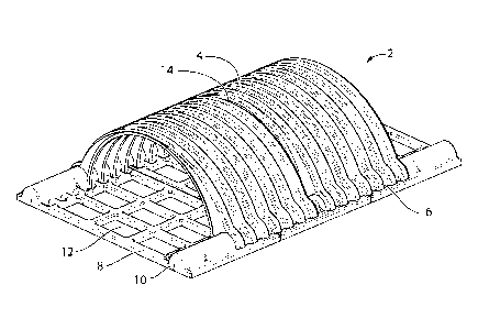
L'invention concerne un nouveau système de caniveau respectueux de l'environnement. L'invention concerne plus précisément un nouveau système de caniveau respectueux de l'environnement, modulaire, à composants multiples, fabriqué à partir de composants obtenus par moulage par injection et réaction. Ce système comprend des bases modulaires pouvant être reliées les unes aux autres, des systèmes d'arcs ondulés modulaires pouvant être reliés les uns aux autres, ainsi que des éléments de liaison modulaires. Un système de caniveau modulaire comprend: (a) au moins un module de grille de base; (b) au moins un module d'arc ondulé reposant sur la grille; et (c) un module de liaison en forme d'arc adjacent au module d'arc.


Abrégé anglais

This invention relates to a novel environmentally compatible culvert system. More particularly, this invention relates to a novel multi-component modular environmental culvert system which is constructed of reaction injection molded components, comprising modular interconnecting bases, modular interconnecting corrugated arch systems, and modular joining binders. A modular culvert system comprising: (a) at least one base grid module; (b) at least one corrugated arch module resting on the grid; and (c) an arch shaped binder module adjacent the arch module.

Revendications

Note : Les revendications sont présentées dans la langue officielle dans laquelle elles ont été soumises.


-7-
WHAT IS CLAIMED IS:
1. A culvert system comprising: (a) at least one base grid module
comprising two side
regions, each of the side regions comprising a rail; (b) at least one
corrugated arch module
resting on the base grid module, the corrugated arch module comprising two
base regions,
each of the base regions comprising a grip for supportive and releasable
engagement by a
corresponding one of the rails of the base grid module wherein depths of
grooves of
corrugations in the corrugated arch module deepen from a top center region to
each of the
grips of the base regions.
2. A system as claimed in claim 1 comprising at least two of the corrugated
arch
modules and an arched binder module for connecting the two corrugated arch
modules.
3. A system as claimed in claim 2 wherein the arched binder module
comprises a T-
shaped cross-section.
4. A system as claimed in claim 2 comprising: at least three base grid
modules adjacent
one another; at least two corrugated arch modules adjacent one another and
offset 50 percent
from the three base grid modules, and wherein the arched binder module fits
between th two
adjacent corrugated arch modules and releasably connects them together.
5. A system as claimed in claim 1 wherein the base grid module comprises a
plurality of
spatial openings at each of the side regions and wherein the corrugated arch
module
comprises a plurality of protrusions at each of the base regions for
supportive engagement by
corresponding spatial openings of the grid module.
6. A system as claimed in claim 1 wherein the rail is formed in the shape
of a semi-
cylinder.
7. A system as claimed in claim 6 wherein the grip is formed in the shape
of a hollow
semi-cylinder.

Description

Note : Les descriptions sont présentées dans la langue officielle dans laquelle elles ont été soumises.


CA 02679462 2009-08-28
WO 2008/104075 PCT/CA2008/000382
ENVIRONMENTAL CULVERT SYSTEM
FIELD OF THE INVENTION
[0001] This invention relates to a novel environmentally compatible culvert
system.
More particularly, this invention relates to a novel multi-component modular
environmental culvert system which is constructed of reaction injection molded
components, comprising modular interconnecting bases, modular interconnecting
corrugated arches, and modular intermediate joining binders.
BACKGROUND OF THE INVENTION
[0002] With increasing emphasis by regulatory authorities on minimizing damage
to the
environment, many jurisdictions have passed laws and regulations which
prohibit the
installation of materials which are regarded as being potentially harmful to
the
environment. Once such area is metal culvert replacement in road and bridge
systems.
In many jurisdictions, it is prohibited to replace existing corroded metal
culverts with
new metal culverts, even galvanized steel culverts. There is a need for an
inexpensive,
readily installable environmentally compatible culvert system that can be used
for
construction of new culverts and replacement of old culverts.
[0003] The foregoing examples of the related art and limitations related
thereto are
intended to be illustrative and not exclusive. Other limitations of the
related art will
become apparent to those of skill in the art upon a reading of the
specification and a
study of the drawings.
SUMMARY OF THE INVENTION
[0004] The following embodiments and aspects thereof are described and
illustrated in
conjunction with systems, tools and methods which are meant to be exemplary
and
illustrative, not limiting in scope. In various embodiments, one or more of
the
above-described problems have been reduced or eliminated, while other
embodiments
are directed to other improvements.
[0005] The invention is directed to a culvert system comprising: (a) at least
one base
grid module; (b) at least one corrugated arch module resting on the grid
module; and
(c) an arched binder module located adjacent the corrugated arch module.
[0006] The base grid module can comprise a plurality of interconnecting ribs
with
spaces therebetween and corrugated arch module receiving rails on each side
thereof.
The base grid module can include spatial openings therein for receiving the
ends of the
corrugated arch module.

CA 02679462 2009-08-28
WO 2008/104075 PCT/CA2008/000382
- 2 -
[0007] The depths of the grooves of the corrugations in the corrugated arch
module can
deepen as the arch extends from the top center to each side at the base of the
arch
module. The lower edges of the arch module can have a series of protrusions
thereon
which can be adapted to fit into spatial openings in the base grid module.
[0008] There can be at least two adjacent arch modules and the arched binder
can be
adapted to fit between the adjacent arch modules, the binder having at the
lower base
thereof protrusions which fit into corresponding openings in the base grid
module.
[0009] The arched binder can have a T-shaped cross-section. The corrugated
arch
receiving rails can have a hollow semi-cylindrical configuration. The
corrugated
arches can be formed in the shape of a hollow half cylinder.
[0010] There can be at least three base grid modules adjacent one another, at
least two
corrugated arch modules adjacent one another and offset 50 percent from the
three base
grid modules, and the arched binder fits between the two adjacent arch modules
and
releasably connects them together.
[0011] In addition to the exemplary aspects and embodiments described above,
further
aspects and embodiments will become apparent by reference to the drawings and
by
study of the following detailed descriptions.
BRIEF DESCRIPTION OF DRAWINGS
[0012] Exemplary embodiments are illustrated in referenced figures of the
drawings. It
is intended that the embodiments and figures disclosed herein are to be
considered
illustrative rather than restrictive.
[0013] Figure 1 illustrates an isometric view of the environmentally
compatible
modular culvert system according to the invention.
[0014] Figure 2 illustrates an exploded isometric view of the environmentally
compatible modular culvert system.
[0015] Figure 3 illustrates an underside isometric view of the environmentally
compatible modular culvert system.
[0016] Figure 4 illustrates a bottom view of the environmentally compatible
modular

CA 02679462 2009-08-28
WO 2008/104075 PCT/CA2008/000382
- 3 -
[0017] Figure 5 illustrates an isometric view of a corrugated arch module.
[0018] Figure 6 illustrates an isometric view of a binder module.
[0019] Figure 7 illustrates a cross-section exploded view of a binder module
positioned
between adjoining edges of two corrugated arch modules.
[0020] Figure 8 illustrates a cross-section view of a binder module fitted
between the
edges of two corrugated arch modules.
[0021] Figure 9 illustrates an isometric view of three adjoining base modules.
[0022] Figure 10 illustrates an underside isometric view of three adjoining
base
modules.
[0023] Figure 11 illustrates a plan view of a wedge-shaped arch module.
[0024] Figure 12 illustrates an isometric view of a wedge-shaped arch module.
DETAILED DESCRIPTION OF THE INVENTION
[0025] Throughout the following description specific details are set forth in
order to
provide a more thorough understanding to persons skilled in the art. However,
well
known elements may not have been shown or described in detail to avoid
unnecessarily
obscuring the disclosure. Accordingly, the description and drawings are to be
regarded
in an illustrative, rather than a restrictive, sense.
[0026] Referring to Figure 1, which illustrates an isometric view of the
modular culvert
system 2, the modular culvert system as seen in Figure 1 comprises two
adjoining
corrugated arch modules 4, which by means of respective cylindrical base grips
6 on
each side, rest on three adjoining base modules 8. The three adjoining base
modules 8
have on each side thereof adjoining cylindrical rails 10, which together
support the
cylindrical base grips 6 of the two adjoining overhead corrugated arch modules
4. The
interior body of the base modules 8 have openings 12 which are arranged in a
grid-like
pattern. The two adjoining corrugated arch modules 4 are connected together by
an
arched binder 14.

CA 02679462 2009-08-28
WO 2008/104075 PCT/CA2008/000382
- 4 -
[0027] It will be understood that the construction shown in Figure 1 and
subsequent
figures is illustrative and that any number of arch modules, base modules and
binders
can be connected together to construct a culvert that is required in the
field. In
practice, the culverts can be short, medium or long in length, and in certain
cases, can
be linear or curved.
[0028] Referring to Figure 2, which illustrates an exploded isometric view of
the
environmentally compatible modular culvert system, the two arch modules 4, the
interconnecting binder 14 and the three base modules 8 are readily visible.
[0029] Referring to Figure 3, which shows an underside isometric view of the
modular
culvert system 2, the modular system comprises two adjoining corrugated arch
modules
4, with cylindrical base grips 6 on each side, which rest on three adjoining
base
modules 8. The three base modules 8 have on each side thereof connecting base
cylindrical rails 10, which together support the cylindrical base grips 6 of
the overhead
corrugated arch modules 4. The arch modules 4 are offset from the base modules
8 by
50 percent.
[0030] Referring to Figure 4, which illustrates a bottom view of the
environmentally
compatible modular culvert system, the modular system comprises two adjoining
corrugated arch modules 4 (partially visible), which by means of cylindrical
base grips
6 (not visible), rest on three adjoining base modules 8. The three base
modules 8 have
on each side thereof a connecting base cylindrical rails 10, which together
support the
cylindrical base grip portions 6 of the overhead corrugated arch modules 4.
Plainly
visible in Figure 4 are the series of corrugated arch prong openings 28 and
intermediate
binder openings 30.
[0031] Referring to Figure 5, which illustrates a detailed isometric view of a
corrugated arch module 4, the module 4 has a pair of hollow cylindrical base
grips 6 on
each side of the base region of the corrugated body portion of the arch module
4. It
will be noted that the lower portions of the edge flanges 16 of the corrugated
arch 4
have proportionally greater depth than the depth of the corrugations at the
top of the
arch module. This design provides greater strength to each side of the base
regions of
the arch module 4. Also, the interiors of the hollow cylindrical grips 6 have
a series of
prongs 18. These spatially arranged series of prongs 18 engage with
corresponding
openings 28 (see Figure 4) in the base module 8, which will be discussed
later. The
corrugations above the grips 6 on each side act as baffles to reduce water
flow velocity
thereby enhancing the passage of fish, such as salmon, through the culvert.

CA 02679462 2009-08-28
WO 2008/104075 PCT/CA2008/000382
- 5 -
[0032] Figure 6 illustrates an isometric view of an arched binder module 14,
with T-
shaped cross-section 20. The arched binder 14 has the same degree of curvature
as the
corrugated arch module 4.
[0033] Figure 7 illustrates a detailed exploded section view of a binder
module 14
between two corrugated arch modules 4. Figure 7 illustrates in particular the
T-shaped
cross-section of the arched binder 14, specifically the horizontal top bar
portion 22, the
main vertical stem 24 and the pair of arch engaging flanges 26 at each end of
the top
bar 22.
[0034] Figure 8 illustrates a cross-section view of a binder module 14 fitted
between
two corrugated arch modules 4. Figure 8 illustrates in particular how the T-
shaped
cross-section of the arched binder 14, specifically the horizontal top bar
portion 22, the
main vertical stem 24 and the pair of arch engaging flanges 26 at each end of
the top
bar 22, engage the adjoining flanges 16 of the adjacent arch modules 4. As can
be
seen, the long stem 24 and the spaces between the stem 24 and the flanges 26
provide a
significant amount of tolerance with the adjoining flanges to accommodate
uneven and
off-level terrain. The joining system also has the advantage that no bolts or
other
connecting fixtures are required to enable arch modules to be movably
connected
together.
[0035] Figure 9 illustrates an isometric view of a trio of adjoining base
modules 8.
This view illustrates in particular the series of prong openings 28 which are
located at
the interior sides of the two side rails 10. These series of openings 28 are
adapted to
receive and hold the series of prongs 18 of the corrugated arch modules 4 (see
Figure
5). The sides of the bars making up the grid-like openings 12 in the base
module 8 are
upwardly tapered so that when freezing conditions exist, and ice forms in the
openings
12, the ice force will not break the ribs of the base module 8 but will expand
upwardly
similar to a conventional ice cube tray. Located on each side in the mid-area
of each
base module 8, on the interior sides of the two rails 10, is a binder opening
30, which
is wider than the neighboring prong openings 28. These openings 30 are adapted
to
receive the T-shaped ends of the binder module 14 as seen in Figures 1, 3 and
4.
When assembled, the corrugated arch modules 4 will be deployed on the trio of
base
grid modules but offset by 50 percent as seen in Figure 1. In this way, there
are no
joints between adjacent arch and base modules that extend in a location around
the
circumference of the modular culvert system 2. This arrangement provides
strength for
the overall culvert system 2.

CA 02679462 2014-07-02
WO 2008/104075 PCT/CA2008/000382
- 6 -
[0036] Figure 10 illustrates an underside isometric view of a trio of base
modules 8.
This view illustrates in particular the series of prong openings 28 which are
adapted to
receive the series of prongs 18 of the corrugated arch modules 4. Figure 10
also
illustrates the intermediate binder openings 30 which are adapted to receive
the ends of
the binder module 14.
[0037] Figure 11 illustrates a plan view of a wedge-shaped corrugated arch
module 32,
with a wide cylindrical base grip 34 at one end and a narrow base grip 36.
This
module 32 can be used to connect adjoining corrugated arch modules 4 when it
is
necessary to deploy the modular culvert system in a curved relationship rather
than a
linear relationship.
[0038] Figure 12 illustrates an isometric view of a wedge-shaped arch module
32. The
wide base grip 34 and the narrow base grip 36 are plainly visible. The shape
of the
wedge module can be varied to accommodate different angles.
[0039] The corrugated arch modules, base modules and binders can be formed
from
appropriate polymers using reaction injection molded technology. The
polymerizing
reaction is exothermic so no mold heating is required. The inventors have
found that
Metton ni Resin, which is available from Metton American Inc. of La Porte,
Texas, is
very strong, readily reaction injection-molded and is environmentally
compatible.
Metton LMR provides part design freedom with integrated functionality and part
consolidation opportunities similar to injection molding for replacement of
traditional
materials such as wood and metal. The molded Metton resin is stronger than
fibreglass, thereby permitting thinner sections, and modules can be produced
from the
mold at 400 F every three to four minutes. This is a much faster production
rate than
fibreglass, which is labor intensive and produces two to three modules per
day. The
MettonTh resin is environmentally friendly and does not leach harmful
ingredients into
the ground water. On incineration, about one third fewer pollutants are
generated than
for conventional incinerated polymers.
[0040] While a number of exemplary aspects and embodiments have been discussed
above, those of skill in the art will recognize certain modifications,
permutations,
additions and sub-combinations thereof. It is therefore intended that the
following
additions and sub-combinations thereof. The scope of the claims should not be
limited by the preferred embodiments set forth in the examples, but should be
given
the broadest interpretation consistent with the description as a whole.

Dessin représentatif
Une figure unique qui représente un dessin illustrant l'invention.
États administratifs

2024-08-01 : Dans le cadre de la transition vers les Brevets de nouvelle génération (BNG), la base de données sur les brevets canadiens (BDBC) contient désormais un Historique d'événement plus détaillé, qui reproduit le Journal des événements de notre nouvelle solution interne.

Veuillez noter que les événements débutant par « Inactive : » se réfèrent à des événements qui ne sont plus utilisés dans notre nouvelle solution interne.

Pour une meilleure compréhension de l'état de la demande ou brevet qui figure sur cette page, la rubrique Mise en garde , et les descriptions de Brevet , Historique d'événement , Taxes périodiques et Historique des paiements devraient être consultées.

Historique d'événement

Description Date
Le délai pour l'annulation est expiré 2022-09-01
Lettre envoyée 2022-02-28
Lettre envoyée 2021-09-01
Lettre envoyée 2021-03-01
Représentant commun nommé 2019-10-30
Requête visant le maintien en état reçue 2017-02-22
Accordé par délivrance 2015-06-16
Inactive : Page couverture publiée 2015-06-15
Préoctroi 2015-03-25
Inactive : Taxe finale reçue 2015-03-25
Un avis d'acceptation est envoyé 2014-10-02
Lettre envoyée 2014-10-02
Un avis d'acceptation est envoyé 2014-10-02
Inactive : Approuvée aux fins d'acceptation (AFA) 2014-08-27
Inactive : Q2 réussi 2014-08-27
Modification reçue - modification volontaire 2014-07-02
Inactive : Lettre officielle 2014-06-04
Inactive : Correspondance - PCT 2014-02-19
Inactive : Dem. de l'examinateur par.30(2) Règles 2014-01-06
Inactive : Rapport - Aucun CQ 2013-12-23
Lettre envoyée 2013-03-01
Exigences pour une requête d'examen - jugée conforme 2013-02-08
Toutes les exigences pour l'examen - jugée conforme 2013-02-08
Requête d'examen reçue 2013-02-08
Lettre envoyée 2012-02-27
Inactive : Transfert individuel 2012-02-02
Inactive : Page couverture publiée 2009-11-19
Inactive : Inventeur supprimé 2009-10-23
Inactive : Lettre officielle 2009-10-23
Lettre envoyée 2009-10-23
Inactive : Notice - Entrée phase nat. - Pas de RE 2009-10-23
Inactive : Inventeur supprimé 2009-10-23
Inactive : CIB en 1re position 2009-10-20
Demande reçue - PCT 2009-10-20
Exigences pour l'entrée dans la phase nationale - jugée conforme 2009-08-28
Demande publiée (accessible au public) 2008-09-04

Historique d'abandonnement

Il n'y a pas d'historique d'abandonnement

Taxes périodiques

Le dernier paiement a été reçu le 2015-02-10

Avis : Si le paiement en totalité n'a pas été reçu au plus tard à la date indiquée, une taxe supplémentaire peut être imposée, soit une des taxes suivantes :

  • taxe de rétablissement ;
  • taxe pour paiement en souffrance ; ou
  • taxe additionnelle pour le renversement d'une péremption réputée.

Les taxes sur les brevets sont ajustées au 1er janvier de chaque année. Les montants ci-dessus sont les montants actuels s'ils sont reçus au plus tard le 31 décembre de l'année en cours.
Veuillez vous référer à la page web des taxes sur les brevets de l'OPIC pour voir tous les montants actuels des taxes.

Titulaires au dossier

Les titulaires actuels et antérieures au dossier sont affichés en ordre alphabétique.

Titulaires actuels au dossier
RONALD W. HAMMERSTEDT
MICHAEL D. RAE
BRIAN SEMOTIUK
Titulaires antérieures au dossier
ROBERT A. SEMOTIUK
Les propriétaires antérieurs qui ne figurent pas dans la liste des « Propriétaires au dossier » apparaîtront dans d'autres documents au dossier.
Documents

Pour visionner les fichiers sélectionnés, entrer le code reCAPTCHA :


Pour visualiser une image, cliquer sur un lien dans la colonne description du document. Pour télécharger l'image (les images), cliquer l'une ou plusieurs cases à cocher dans la première colonne et ensuite cliquer sur le bouton "Télécharger sélection en format PDF (archive Zip)" ou le bouton "Télécharger sélection (en un fichier PDF fusionné)".

Liste des documents de brevet publiés et non publiés sur la BDBC .

Si vous avez des difficultés à accéder au contenu, veuillez communiquer avec le Centre de services à la clientèle au 1-866-997-1936, ou envoyer un courriel au Centre de service à la clientèle de l'OPIC.


Description du
Document 
Date
(aaaa-mm-jj) 
Nombre de pages   Taille de l'image (Ko) 
Abrégé 2009-08-27 1 76
Dessins 2009-08-27 12 884
Description 2009-08-27 6 336
Dessin représentatif 2009-08-27 1 44
Revendications 2009-08-27 2 50
Dessins 2014-07-01 12 364
Description 2014-07-01 6 336
Revendications 2014-07-01 1 40
Dessin représentatif 2015-05-20 1 37
Avis d'entree dans la phase nationale 2009-10-22 1 193
Courtoisie - Certificat d'enregistrement (document(s) connexe(s)) 2009-10-22 1 102
Courtoisie - Certificat d'enregistrement (document(s) connexe(s)) 2012-02-26 1 102
Rappel - requête d'examen 2012-10-29 1 117
Accusé de réception de la requête d'examen 2013-02-28 1 176
Avis du commissaire - Demande jugée acceptable 2014-10-01 1 161
Avis du commissaire - Non-paiement de la taxe pour le maintien en état des droits conférés par un brevet 2021-04-18 1 535
Courtoisie - Brevet réputé périmé 2021-09-21 1 547
Avis du commissaire - Non-paiement de la taxe pour le maintien en état des droits conférés par un brevet 2022-04-10 1 541
PCT 2009-08-27 2 62
Correspondance 2009-10-22 1 16
Correspondance 2014-02-18 1 34
Correspondance 2014-06-03 1 13
Correspondance 2015-03-24 1 55
Paiement de taxe périodique 2017-02-21 1 36