Sélection de la langue

Search

Sommaire du brevet 2679685 

Énoncé de désistement de responsabilité concernant l'information provenant de tiers

Une partie des informations de ce site Web a été fournie par des sources externes. Le gouvernement du Canada n'assume aucune responsabilité concernant la précision, l'actualité ou la fiabilité des informations fournies par les sources externes. Les utilisateurs qui désirent employer cette information devraient consulter directement la source des informations. Le contenu fourni par les sources externes n'est pas assujetti aux exigences sur les langues officielles, la protection des renseignements personnels et l'accessibilité.

Disponibilité de l'Abrégé et des Revendications

L'apparition de différences dans le texte et l'image des Revendications et de l'Abrégé dépend du moment auquel le document est publié. Les textes des Revendications et de l'Abrégé sont affichés :

  • lorsque la demande peut être examinée par le public;
  • lorsque le brevet est émis (délivrance).
(12) Demande de brevet: (11) CA 2679685
(54) Titre français: PROCEDE DE FABRICATION D'UNE CELLULE SOLAIRE ET CELLULE SOLAIRE AINSI FABRIQUEE
(54) Titre anglais: METHOD FOR THE MANUFACTURE OF A SOLAR CELL AND THE RESULTING SOLAR CELL
Statut: Réputée abandonnée et au-delà du délai pour le rétablissement - en attente de la réponse à l’avis de communication rejetée
Données bibliographiques
(51) Classification internationale des brevets (CIB):
  • H01L 31/18 (2006.01)
(72) Inventeurs :
  • HABERMANN, DIRK (Allemagne)
  • MULLER, PATRIK (Suisse)
(73) Titulaires :
  • SCHMID TECHNOLOGY SYSTEMS GMBH
(71) Demandeurs :
  • SCHMID TECHNOLOGY SYSTEMS GMBH (Allemagne)
(74) Agent: NORTON ROSE FULBRIGHT CANADA LLP/S.E.N.C.R.L., S.R.L.
(74) Co-agent:
(45) Délivré:
(86) Date de dépôt PCT: 2008-03-04
(87) Mise à la disponibilité du public: 2008-09-12
Licence disponible: S.O.
Cédé au domaine public: S.O.
(25) Langue des documents déposés: Anglais

Traité de coopération en matière de brevets (PCT): Oui
(86) Numéro de la demande PCT: PCT/EP2008/001702
(87) Numéro de publication internationale PCT: WO 2008107156
(85) Entrée nationale: 2009-09-01

(30) Données de priorité de la demande:
Numéro de la demande Pays / territoire Date
10 2007 012 268.5 (Allemagne) 2007-03-08

Abrégés

Abrégé français

L'invention concerne un procédé de fabrication d'une cellule solaire (20). Sur la face avant et la face arrière d'un substrat en silicium (4), on applique d'abord une première couche anti-réflexion (2, 5) ayant un indice de réfraction optique n compris entre 3,6 et 3,9. On applique sur cette couche une deuxième couche anti-réflexion (1, 6) ayant un indice de réfraction optique n compris entre 1,94 et 2,1. Les couches anti-réflexion (1, 2, 5, 6) sont sectionnées jusqu'au substrat en silicium (4), pour amener des contacts métalliques (7, 9) jusqu'au substrat en silicium (4).


Abrégé anglais

In a method for producing a solar cell (20) from a silicon substrate (4), a first anti-reflective layer (2, 5) having an optical refraction index n between 3.6 and 3.9 is first applied to the front and back. Then a second anti-reflective layer (1, 6) having an optical refraction index n between 1.94 and 2.1 is applied thereon. The anti-reflective layers (1, 2, 5, 6) are severed down to the silicon substrate (4) underneath in order to insert metal contacts (7, 9) to the silicon substrate (4) therein.

Revendications

Note : Les revendications sont présentées dans la langue officielle dans laquelle elles ont été soumises.


-9-
CLAIMS
1. Method for the manufacture of a solar cell (20, 120, 220) from silicon,
wherein to at least one side of a doped silicon substrate (4, 104, 204) is ap-
plied a first coating (2, 5, 102, 105, 202, 205) with an optical refractive
index
n between 3.5 and 4.0 and to said first coating (2, 5, 102, 105, 202, 205) is
applied a second coating (1, 6, 101, 106, 201, 206) with an optical refractive
index n between 1.9 and 2.2.
2. Method according to claim 1, wherein the first coating (2, 5, 102, 105,
202,
205) has a refractive index n between 3.6 and 3.9.
3. Method according to claim 1, wherein the first coating (2, 5, 102, 105,
202,
205) comprises silicon and/or germanium, wherein it is preferably a-SiGe or
a-SiGeH.
4. Method according to one of the preceding claims, wherein the first coating
(2, 5, 102, 105, 202, 205) comprises SiGe, wherein preferably at least the
first coating (2, 5, 102, 105, 202, 205), in particular also the second
coating
(1, 6, 101, 106, 201, 206) or both coatings together respectively, has a ris-
ing germanium concentration gradient or such a gradient is effected.
5. Method according to one of the preceding claims, wherein the second coat-
ing (1, 6, 101, 106, 201, 206) has a refractive index n between 1.94 and 2.1.
6. Method according to one of the preceding claims, wherein the second coat-
ing (1, 6, 101, 106, 201, 206) comprises silicon, wherein it is preferably
SiN(x):H.
7. Method according to one of the preceding claims, wherein the first coating
(2, 5, 102, 105, 202, 205) is firstly applied to both sides of a doped silicon
substrate (4, 104, 204) and then the second coating (1, 6, 106, 106, 201,
206) is applied to both sides.

-10-
8. Method according to one of the preceding claims, wherein at least on one
side of the silicon substrate (4, 104, 204) the two coatings (1, 2, 5, 6, 101,
102, 105, 106, 201, 202, 205, 206) are at least partly, preferably in linear
manner, removed for the application of a contact (7, 9, 107, 109, 207, 209)
to the underlying doped silicon substrate (4, 104, 204).
9. Method according to one of the preceding claims, wherein an electrical con-
tact (107, 109, 207, 209), preferably in linear manner, is applied to the sili-
con substrate (104, 2040 in such a way that the first coating (102, 202, 205)
is not in direct contact with the electrical contact, wherein preferably the
first
coating (102, 202, 205) is separated by a dielectric coating (112, 212, 213),
preferably made from SiN, from the electrical contact.
10. Method according to one of the preceding claims, wherein following the ap-
plication of the first coating (102, 202, 205) the latter is structured with a
structural pattern corresponding to the electrical contacts (109, 207, 209) to
be applied and with a greater width than the electrical contacts (109, 207,
209) and then the second coating (101, 201, 206) is applied to the first coat-
ing (102, 202, 205) and a contact structure is introduced into the first coat-
ing (101, 201, 206) with the final pattern of the electrical contacts and sub-
sequently the electrical contacts (109, 207, 209) are introduced into this
contact structure.
11. Method according to one of the preceding claims, wherein the silicon sub-
strate (4, 104, 204) is n-doped on a top side (3, 103, 203), preferably with
phosphorus, wherein on the back surface is produced a p-doped coating, in
particular being a thinner coating, wherein preferably the p-doped coating is
made from a-Si:Ge-boron or is doped with a-Si:Ge-boron.
12. Solar cell (20, 120, 220), wherein it is made from a silicon substrate (4,
104,
204), which is treated using a method according to one of the preceding
claims.

Description

Note : Les descriptions sont présentées dans la langue officielle dans laquelle elles ont été soumises.

CA 02679685 2009-09-01
-1-
DESCRIPTION
METHOD FOR THE MANUFACTURE OF A SOLAR
CELL AND THE RESULTING SOLAR CELL
FIELD OF APPLICATION AND PRIOR ART
The invention relates to a method for the manufacture of a solar cell from
silicon
or a silicon substrate, as well as a solar cell manufactured using such a
method.
Normally the efficiency of solar cells is influenced by the nature of the
surface of
said solar cell or a surface coating. Particular significance is attributed to
the anti-
reflection and passivation characteristics, so as to in particular permit a
maximum
incidence of sunlight into the solar cell. Normally the front surface of a
solar cell
has an antireflection coating, e.g. of SiN.
The manufacture of a conventional solar cell involves a sequence of process
steps, described in summary form hereinafter. The basis is usually provided by
monocrystalline or polycrystalline p-Si wafers, which are surface-textured by
means of an etching process in order to improve the absorption properties. In
the
case of monocrystalline silicon the etching process is carried out with a
mixture of
sodium or potassium hydroxide solution and isopropyl alcohol. Polycrystalline
sili-
con is etched with a solution of hydrofluoric and nitric acid. Further etching-
cleaning sequences are then performed in order to provide an optimum prepara-
tion of the surface for the following diffusion process. In said process a p-n
junc-
tion in silicon is produced by the diffusion of phosphorus to a depth of
approxi-
mately 0.5 pm. The p-n junction separates the charge carriers formed by light.
For producing the p-n junction the wafer is heated to approximately 800 C to
950 C in a furnace in the presence of a phosphorus source, usually a gas
mixture
or an aqueous solution. The phosphorus penetrates the silicon surface. The
phosphorus-doped coating is negatively conductive as opposed to the positively
conductive boron-doped base. In this process a phosphorus glass is formed on
the surface and is removed in the following steps by etching with HF. Subse-

CA 02679685 2009-09-01
-2-
quently to the silicon surface is applied a roughly 80 nm thick coating,
usually
comprising SiN:H, in order to reduce reflection and for passivation purposes.
Me-
tallic contacts are then applied to the front surface (silver) and back
surface (gold
or silver). In order to produce a so-called BSF (Back Surface Field), advanta-
geously of aluminium, in said process part of the aluminium applied to the
wafer
back surface is alloyed into the silicon in the following firing step.
PROBLEM AND SOLUTION
The problem of the invention is to provide an aforementioned method and a
solar
cell manufactured therewith enabling the disadvantages of the prior art to be
avoided and more particularly to further increase the efficiency of a solar
cell.
This problem is solved by a method having the features of claim 1 and a solar
cell
having the features of claim 13. Advantageous and preferred developments of
the
invention form the subject matter of the further claims and are explained in
greater
detail hereinafter. Furthermore, by express reference the wording of the
priority
application DE 102007012268.5 filed on March 8, 2007 by the same applicant is
made into the content of the present description. By express reference the
word-
ing of the claims is made into the content of the present description.
According to the invention to at least one side of a doped silicon substrate,
which
is therefore already pretreated for the further production of a solar cell, is
applied a
first coating having an optical refractive index n, which is between 3.5 and
4Ø To
said first coating is applied a second coating with an optical refractive
index n be-
tween 1.9 and 2.2. Thus, within the scope of the present invention a two-layer
structure is created for a surface coating of a solar cell or an
antireflection coating.
This makes it possible to reduce the reflection of light striking the solar
cell, so that
more light strikes the solar cell and the efficiency of the latter is
consequently in-
creased. As a result of such a multilayer structure it is also possible to
improve
the passivation of the front surface of the solar cell.
According to a development of the invention the first coating can have a
refractive
index between 3.6 and 3.9. It can comprise or be formed from silicon and/or
ger-

CA 02679685 2009-09-01
-3-
manium. It is advantageously formed from a SiGe or a-SiGe:H. Thus, in this
case
said coating of said material is not used as a semiconductor coating, but
instead is
intended for an antireflecting function.
In a further development of the invention the second coating can have a
refractive
index n between 1.94 and 2.1. As a result of such a coating structure a
particu-
larly satisfactorily acting, overall antireflection coating is obtained.
Moreover the
second coating can comprise or be formed from silicon, advantageously
SiN(x):H.
It is admittedly possible, e.g. in the case of a solar cell only irradiated on
the front
surface, to provide such a double coating or layer structure for an
antireflection
coating solely on the front surface. However, advantageously both sides of the
solar cell have such a double layer structure, at least if the two sides are
to be ir-
radiated with light.
In a manufacturing method it is possible to firstly coat both sides of the
silicon
substrate with the first coating. Then the second coating can be applied to
both
sides, which leads to a process technology that can be handled more readily.
According to a development of the invention the first coating can comprise
silicon
and germanium, e.g. the aforementioned compounds. It is possible for at least
the first coating and in particular also the second coating or the first
coating and
second coating together, to have a rising geranium concentration gradient.
Such
a gradient can e.g. be produced during the production or application of the
coat-
ings. This makes it possible to positively influence the antireflection
characteris-
tics and passivation characteristics.
During further processing of the silicon substrate it is possible at least on
one sub-
strate side to partly remove the coatings in order to produce or apply a
contact to
the underlying doped silicon substrate. Such a contact is advantageously
metallic
or is made from metal. It can advantageously be linear or lattice-like, but at
least
on the front surface of the solar cell only takes up a minimum surface area so
as
to ensure that there is only the minimum shading.

CA 02679685 2009-09-01
-4-
According to a further development of the invention an electrical contact,
such as
is e.g. applied as a line contact, is so produced that it is not directly
touched by the
first coating or does not have any connection therewith. For this purpose e.g.
the
first coating can be separated by a dielectric coating from the electrical
contact
and such a dielectric coating is e.g. made from SiN. Advantageously the
dielectric
coating is formed by the second coating. In an inventive manufacturing method
it
is possible for the first coating to be applied to the silicon substrate and
then struc-
tured in such a way that a structural pattern fundamentally corresponds to the
shape of the electrical contacts which must be applied. However, it is
possible for
a structure to be introduced over a somewhat greater surface area or in each
case
with a somewhat greater width into the coating or the same can be removed.
Then the second coating is applied to the first coating and then the second
coat-
ing is also introduced into the areas which have been correspondingly removed
in
the first coating in accordance with the structural pattern. Subsequently the
sec-
ond coating is structured with a thinner pattern or is removed down to the
underly-
ing silicon substrate in such a way that in the resulting structure the
electrical con-
tacts can be introduced with the desired pattern. In this way not only is the
inven-
tive layer structure achieved, but simultaneously the electrical contacts do
not
come into contact with the first coating. Structuring of the coatings can e.g.
take
place mechanically, but advantageously lasers are used.
For preparation purposes and prior to the application of the inventive
coatings, a
top side of the silicon substrate can be n-doped, advantageously with
phosphorus.
A p-doped coating can be produced on the back surface, which should be thinner
and is advantageously doped with or made from aSiGe-boron.
It is possible to provide an above-described, two-layer structure for
antireflection
and passivation characteristics on both sides of the substrate and an
electric, pre-
viously described contacting is provided on both sides. A back layer structure
is
applied to the p-doped silicon.
These and further features can be gathered from the claims, description and
drawings and the individual features, both singly or in the form of subcombina-
tions, can be implemented in an embodiment of the invention and in other
fields

CA 02679685 2009-09-01
-5-
and can represent advantageous, independently protectable constructions for
which protection is claimed here. The subdivision of the application into
individual
sections and the subheadings in no way restrict the general validity of the
state-
ments made thereunder.
DETAILED DESCRIPTION OF THE EMBODIMENTS
Embodiments of the invention are diagrammatically represented in the attached
drawings, wherein show:
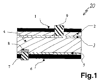
Fig. 1 A section through a solar cell with two coatings having different
optical
refractive indices on both sides, as well as contacts introduced into the
same.
Fig. 2 A variant of the solar cell of fig. 1 with a somewhat modified contact
arrangement on the front surface.
Fig. 3 A further variant of the solar cell of fig. 1 with a further modified
con-
tacting on the front and back surfaces.
DETAILED DESCRIPTION OF THE EMBODIMENTS
Fig. 1 shows in section a solar cell 20. On a p-doped silicon substrate 4 a
thinner
coating 3 of phosphorus-doped n-silicon is applied to the upwardly directed
front
surface. The front, first antireflection coating 2 having an optical
refractive index n
between 3.6 and 3.9 is applied to the coating 3. To said front, first coating
2 is
applied a front, second antireflection coating 1, whose optical refractive
index n is
between 1.94 and 2.1.
On the back surface of substrate 4 is provided a back, first antireflection
coating 5,
whose refractive index n corresponds to the front, first antireflection
coating 2. On
the same is once again provided a back, second antireflection coating 6, whose
refractive index n once again corresponds to the front, first antireflection
coating 1.

CA 02679685 2009-09-01
-6-
The coating of the substrate 4 or the prior doping has been described in
detail
hereinbefore. Advantageously to the substrate 4 with the front n-silicon
coating 3
is firstly applied the front and back, first antireflection coatings 2 and 5.
In a fur-
ther method step the front and back, second antireflection coatings 1 and 6
are
applied.
For the production of the electrical contacts, trenches are made, e.g. by
laser ma-
chining, in the front surface or the front, first and second antireflection
coatings 1
and 2. Into said trenches are introduced metal contacts 9 in the manner de-
scribed hereinbefore, e.g. by printing. Electrical contact 9 is advantageously
made from aluminium and also contacts the n-silicon coating 3.
A similar contacting is carried out on the back surface of solar cell 20 and
firstly
the two back antireflection coatings 5 and 6 are separated down to the
substrate
4. In the resulting trenches are introduced a further metallic contact 7 made
from
aluminium, similar to what was described previously for the front surface. Be-
tween the aluminium contact 7 and the substrate 4 of p-doped silicon is formed
a
so-called aluminium back surface field 8, as is generally known to the expert.
The advantage of the double antireflection coatings 1 and 2 on the front
surface,
as well as coatings 5 and 6 on the back surface of the solar cell 20 compared
with
conventional single-layer antireflection coatings, e.g. of SiN, is the much
lower re-
flectivity, particularly in the wavelength range below 550 nm and above 700
nm.
Therefore the light efficiency and therefore also the energy efficiency of the
inven-
tive solar cell is significantly improved.
Fig. 2 shows a further solar cell 120 once again constituted by a substrate
104, as
described in connection with fig. 1, which has on its top side a phosphorus-
doped,
n-silicon coating 103. First antireflection coatings 102 and 105 are applied
to the
front and back surfaces and to these are once again applied second
antireflection
coatings 101 and 106. The optical refractive indices can be the same as de-
scribed relative to fig. 1.

CA 02679685 2009-09-01
-7-
Whereas on the back surface contacting once again takes place with an alumin-
ium metal contact 107 introduced into a trench in the two back antireflection
coat-
ings and with the resulting aluminium back surface field 108, contacting on
the
front surface is somewhat different. Here in the front, first antireflection
coating
102 is made a trench or the latter is only separated to a width which is much
lar-
ger than the electrical contact 109 to be subsequently applied. The front,
second
antireflection coating 101 is then applied and in it is formed a further
trench or it is
separated down to the n-silicon coating 103 over a width corresponding to that
of
the contact 109. Subsequently the contact 109 is introduced in the manner de-
scribed hereinbefore. The advantage here is that the metallic contact 109, as
de-
scribed hereinbefore, is only directly connected to the n-silicon coating 103
or con-
tacted therewith, but not with the front, first antireflection coating 102.
The por-
tions of the front, second antireflection coating 101 located between the
front, first
antireflection coating 102 and the metal contact 109, act as a dielectric
coating for
isolating the front surface contact of solar cell 120.
Fig. 3 shows another variant of a solar cell 220, which in much the same way
as in
fig. 2 provides for the formation of the front-surface contacting also on the
back
surface. This means that between the back-surface, first antireflection
coating
205 and the back-applied aluminium metal contacts 207 extends part of the back-
surface, second antireflection coating 206 with portions 213 on the back
surface of
substrate 204. Portions 213 form a dielectric coating for isolating the back-
surface
metal contact 207 with respect to the back-surface, first antireflection
coating 205.
Here the aluminium back surface field 208 is once again formed. Otherwise the
structure of the solar cell 220 with substrate 204, n-silicon coating 203 and
front-
surface antireflection coating through the front, first antireflection coating
202 and
the front, second antireflection coating 201 with the front surface metal
contact
209 corresponds to the structure of fig. 2 and this also applies to the
manufactur-
ing method.
The form of the front and back-surface contacts is always the same in the draw-
ings shown, but can also differ, e.g. on one side there can be linear contacts
and
on the other side contact shapes differing therefrom.

CA 02679685 2009-09-01
-8-
As a result of the characteristics of the first antireflection coating,
particularly on
the front surface, with respect to the underlying silicon substrate it is
possible to
bring about an optimum adjustment of the optical characteristics. In addition,
a
very strain-free coating of the silicon substrate is possible.

Dessin représentatif
Une figure unique qui représente un dessin illustrant l'invention.
États administratifs

2024-08-01 : Dans le cadre de la transition vers les Brevets de nouvelle génération (BNG), la base de données sur les brevets canadiens (BDBC) contient désormais un Historique d'événement plus détaillé, qui reproduit le Journal des événements de notre nouvelle solution interne.

Veuillez noter que les événements débutant par « Inactive : » se réfèrent à des événements qui ne sont plus utilisés dans notre nouvelle solution interne.

Pour une meilleure compréhension de l'état de la demande ou brevet qui figure sur cette page, la rubrique Mise en garde , et les descriptions de Brevet , Historique d'événement , Taxes périodiques et Historique des paiements devraient être consultées.

Historique d'événement

Description Date
Inactive : CIB attribuée 2015-12-18
Inactive : CIB en 1re position 2015-12-18
Inactive : CIB expirée 2014-01-01
Inactive : CIB enlevée 2013-12-31
Demande non rétablie avant l'échéance 2012-03-05
Le délai pour l'annulation est expiré 2012-03-05
Réputée abandonnée - omission de répondre à un avis sur les taxes pour le maintien en état 2011-03-04
Lettre envoyée 2010-01-19
Inactive : Lettre officielle 2010-01-19
Inactive : Page couverture publiée 2009-11-19
Inactive : Transfert individuel 2009-11-16
Inactive : Déclaration des droits - PCT 2009-11-16
Inactive : Lettre de courtoisie - PCT 2009-10-23
Inactive : Notice - Entrée phase nat. - Pas de RE 2009-10-23
Inactive : CIB en 1re position 2009-10-22
Demande reçue - PCT 2009-10-21
Exigences pour l'entrée dans la phase nationale - jugée conforme 2009-09-01
Demande publiée (accessible au public) 2008-09-12

Historique d'abandonnement

Date d'abandonnement Raison Date de rétablissement
2011-03-04

Taxes périodiques

Le dernier paiement a été reçu le 2010-02-04

Avis : Si le paiement en totalité n'a pas été reçu au plus tard à la date indiquée, une taxe supplémentaire peut être imposée, soit une des taxes suivantes :

  • taxe de rétablissement ;
  • taxe pour paiement en souffrance ; ou
  • taxe additionnelle pour le renversement d'une péremption réputée.

Veuillez vous référer à la page web des taxes sur les brevets de l'OPIC pour voir tous les montants actuels des taxes.

Historique des taxes

Type de taxes Anniversaire Échéance Date payée
Taxe nationale de base - générale 2009-09-01
Enregistrement d'un document 2009-11-16
TM (demande, 2e anniv.) - générale 02 2010-03-04 2010-02-04
Titulaires au dossier

Les titulaires actuels et antérieures au dossier sont affichés en ordre alphabétique.

Titulaires actuels au dossier
SCHMID TECHNOLOGY SYSTEMS GMBH
Titulaires antérieures au dossier
DIRK HABERMANN
PATRIK MULLER
Les propriétaires antérieurs qui ne figurent pas dans la liste des « Propriétaires au dossier » apparaîtront dans d'autres documents au dossier.
Documents

Pour visionner les fichiers sélectionnés, entrer le code reCAPTCHA :


Pour visualiser une image, cliquer sur un lien dans la colonne description du document. Pour télécharger l'image (les images), cliquer l'une ou plusieurs cases à cocher dans la première colonne et ensuite cliquer sur le bouton "Télécharger sélection en format PDF (archive Zip)" ou le bouton "Télécharger sélection (en un fichier PDF fusionné)".

Liste des documents de brevet publiés et non publiés sur la BDBC .

Si vous avez des difficultés à accéder au contenu, veuillez communiquer avec le Centre de services à la clientèle au 1-866-997-1936, ou envoyer un courriel au Centre de service à la clientèle de l'OPIC.


Description du
Document 
Date
(aaaa-mm-jj) 
Nombre de pages   Taille de l'image (Ko) 
Description 2009-09-01 8 372
Abrégé 2009-09-01 1 14
Dessins 2009-09-01 2 31
Revendications 2009-09-01 2 87
Dessin représentatif 2009-11-19 1 9
Page couverture 2009-11-19 2 42
Avis d'entree dans la phase nationale 2009-10-23 1 193
Rappel de taxe de maintien due 2009-11-05 1 112
Courtoisie - Certificat d'enregistrement (document(s) connexe(s)) 2010-01-19 1 125
Courtoisie - Lettre d'abandon (taxe de maintien en état) 2011-04-29 1 173
PCT 2009-09-01 2 78
Correspondance 2009-10-23 1 20
Correspondance 2009-11-16 3 90
Correspondance 2010-01-19 1 17